IR Energy EvenTube ETS Manual

SERIES EVEN-TUBE 1 10-03-2017
Installation, Operation and Service Instructions
INFRARED HEATER
WARNING
FOR YOUR SAFETY
Improper installation, adjustment, alteration, service or
maintenance can cause property damage, injury or death.
Read the installation, operating and maintenance
instructions thoroughly before installing or servicing this
equipment.
Do not store or use gasoline or other flammable vapors and
liquids in the vicinity of this or any other appliance.
If you smell gas:
1. Open windows
2. Don’t touch electrical switches
3. Extinguish any open flame
4. Immediately call your gas supplier
OWNER
INSTALLER
Retain this Manual & ensure available for Service.
Improper installation, adjustment, alteration, service or
maintenance can cause injury, death or property damage.
Read the installation, operation and service instructions
thoroughly before installing or servicing this equipment.
Provide Manual to owner upon completion of installation!
Read and thoroughly understand these Instructions before
attempting any installation.
Canada: 563 Barton Street, Stoney Creek, Ontario L8E 5S1
USA: 980 Cobb Place Blvd, NW#100 Kennesaw, GA 30144
www.irenergy.ca LT213
WARNING: FOR OUTDOOR USE ONLY
SERIES EvenTube®
Model ETS Infrared Patio Heater
Two-Stage

SERIES EVEN-TUBE 2 10-03-2017
Table of Contents
CAUTION AND GENERAL SAFETY
SAFETY REQUIREMENTS ..............................................................................................................................................................4
GENERAL
INSTALLATION CODES .................................................................................................................................................................5
GENERAL INSTALLATION AND GAS CODES .......................................................................................................................................5
GAS SUPPLY LINES .....................................................................................................................................................................5
ELECTRICAL...............................................................................................................................................................................5
SPECIFICATIONS
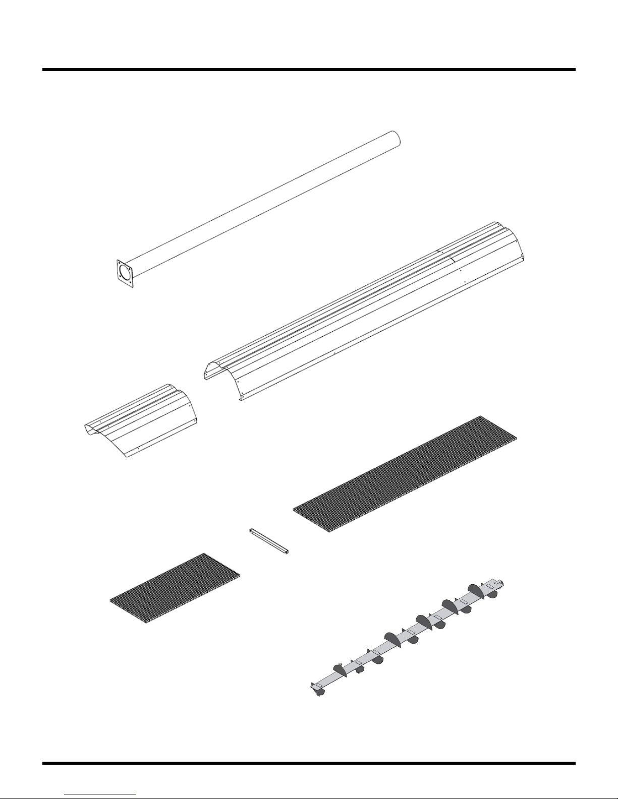
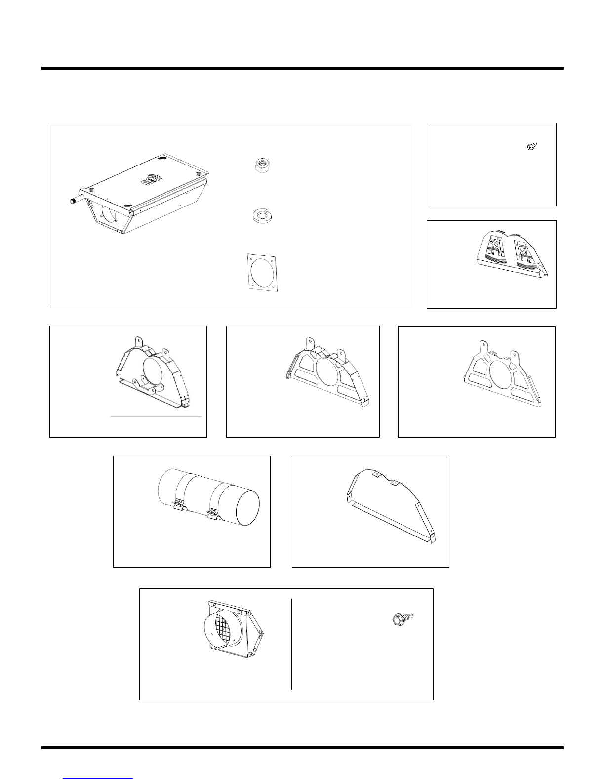
HEATER COMPONENTS:ETS 50...................................................................................................................................................6
HEATER COMPONENTS:ETS 60, 80, 100 .....................................................................................................................................8
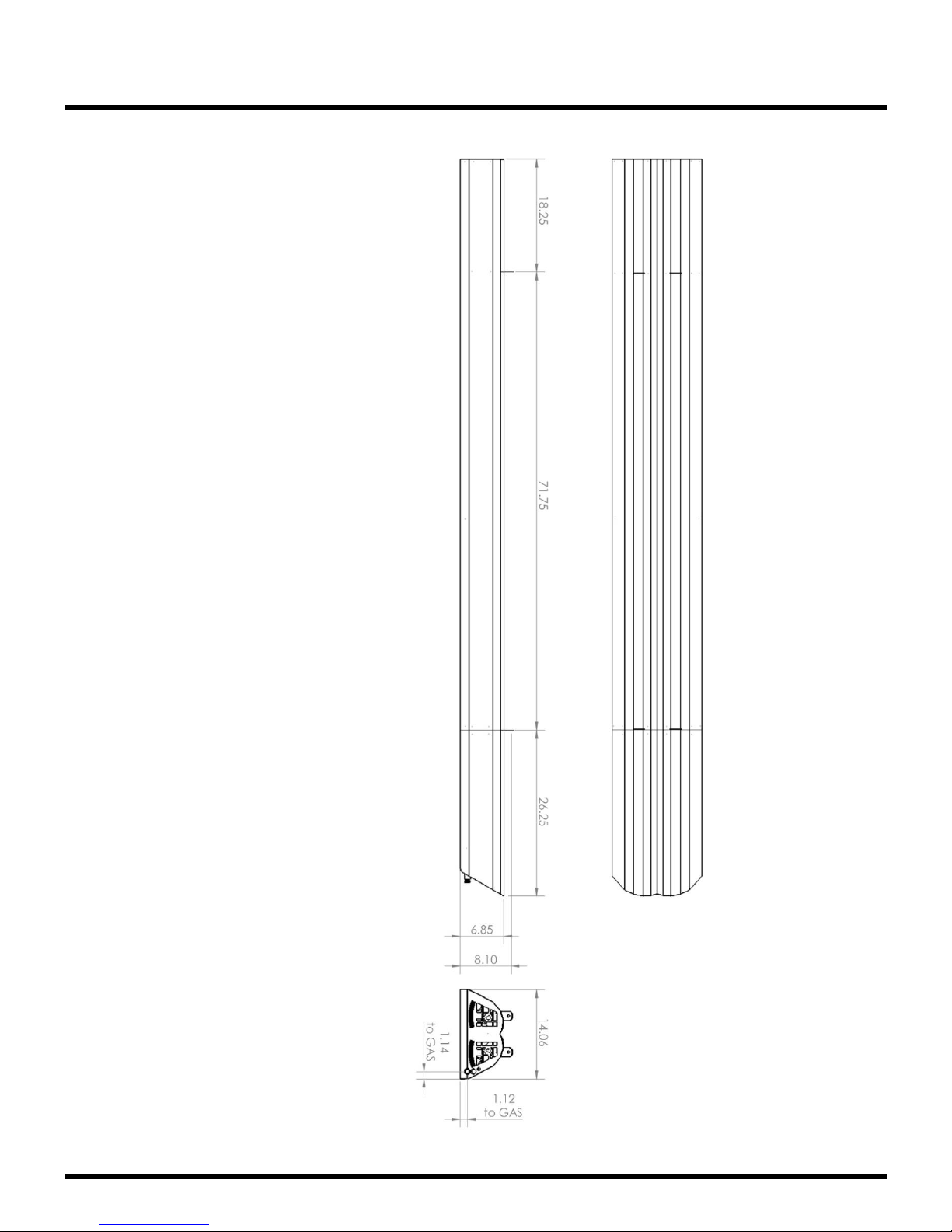
DIMENSIONAL DETAILS:ETS 50 ................................................................................................................................................10
DIMENSIONAL DETAILS:ETS 60, 80, 100 ...................................................................................................................................11
INSTALLATION REQUIREMENTS
POWER &GAS SPECIFICATIONS ..................................................................................................................................................12
CLEARANCE TO COMBUSTIBLES ...................................................................................................................................................13
HEATER MOUNTING.................................................................................................................................................................14
VENTING ................................................................................................................................................................................14
INSTALLATION /CODE REQUIREMENTS.........................................................................................................................................15
INSTALLATION INSTRUCTIONS
INSTALLATION –ETS 60, 80, 100 ..............................................................................................................................................16
INSTALLATION –ETS 50 ...........................................................................................................................................................32
WIRING DIAGRAMS
GENERAL REQUIREMENTS..........................................................................................................................................................34
EXTERNAL WIRING OPTIONS ......................................................................................................................................................35
LIGHTING & SHUTDOWN INSTRUCTIONS
LIGHTING ...............................................................................................................................................................................36
SHUT DOWN...........................................................................................................................................................................36
MAINTENANCE & TROUBLE SHOOTING
MAINTENANCE ........................................................................................................................................................................37
TROUBLE SHOOTING.................................................................................................................................................................37
TROUBLESHOOTING CHART........................................................................................................................................................39
REPLACEMENT PARTS LIST ......................................................................................................................................... 40
WARRANTY ................................................................................................................................................................. 41

SERIES EVEN-TUBE 3 10-03-2017
DANGER - CARBON MONOXIDE HAZARD
This appliance can produce carbon monoxide which has no odor.
Using it in an enclosed space can kill you.
Never use this appliance in an enclosed space such as a camper, tent, car or home.
WARNING - ELECTRICAL GROUNDING INSTRUCTIONS
This heater is equipped with a three-prong (grounding) plug for your protection against shock
hazard and should be plugged directly into a properly grounded three-prong receptacle. Do not
cut or remove the grounding prong from this plug.
Keep any electrical supply cord away from any heated surfaces.
CAUTION - MAINTENANCE INSTRUCTION
1. Keeping the appliance area clear and free from combustible materials, gasoline and other
flammable vapors and liquids.
2. Not obstructing the flow of combustion and ventilation air.
3. Visually checking burner flames.
4. Cleaning the appliance, including special surfaces, with recommended cleaning agents, if
necessary.
Check the maintenance section in this manual for additional instructions.
CAUTION - INSTALLATION
This appliance shall be used only in a well-ventilated space and shall not be used in a building,
garage or any other enclosed area.
The appliance may be installed with shelter no more inclusive than:
1. With walls on all sides, but with no overhead cover.
2. Within a partial enclosure which includes an overhead cover and no more than two
side walls. These side walls may be parallel, as in a breezeway, or at right angles to
each other.
3. Within a partial enclosure which includes an overhead cover and three side walls, as
long as 30 percent or more of the horizontal periphery of the enclosure is permanently
open.

SERIES EVEN-TUBE 4 10-03-2017
Caution and General Safety
At all times maintain clearance to combustible materials as further specified in this manual.
Failure to do so can result in serious fire hazard.
Never operate heaters in atmosphere containing flammable vapours or combustible dusts.
This heater is equipped with an electronic and automatic ignition device. Do not attempt to
light the burner by hand. Failure to comply can result in a serious fire and personal injury
hazard.
Certain materials, when stored under this heater are subjected to radiant heat can soften,
distort or otherwise be damaged, special care should be taken of plastic materials
Appliance surfaces, other than the obvious flame and emitter surfaces, attain elevated
temperatures during operation. Do not touch the heater head during operation. Everyone
should be alerted to this hazard to avoid burning.
Children should be strictly supervised when in the area of this heating appliance. Playing or
running around the structure should be strictly forbidden.
Clothing or other flammable materials should not be hung on or near this heater.
Any guard or other protective device removed for servicing the heater must be replaced
prior to operating the heater.
Installation and repair should be done by a qualified service person. The heater should be
inspected before use and at least annually by a qualified service person.
Safety Requirements
1. Never locate the heater directly below electrical lines, gas lines or sprinkler systems.
2. Do not locate heater too close to vinyl or plastic wall coverings. These materials may
discolour or soften well before they reach combustible limits.
3. The heater requires a minimum clearance from combustible materials. See the
Clearance to Combustible Materials section for specific requirements.
4. Always allow room for maintenance purposes.
5. The heater aspirates air for combustion. Do not locate heater where there are severe
draft conditions or airflow restrictions to the burner.
CAUTION: FIRE OR BURN INJURY HAZARD

SERIES EVEN-TUBE 5 10-03-2017
General
Installation Codes
Installations must comply with local building codes, or in their absence, the latest edition of the
national regulations and procedures as listed below.
General Installation and Gas Codes
Heaters must be installed only for use with the type of gas appearing on the rating plate, and the
installation must conform to the National Fuel Gas Code, ANSI Z223.1/NFPA 54 in the US and
CSA B149.1 Natural Gas & Propane Installation Code in Canada.
This heater is approved for outdoor installation only. Not for use in residential dwellings, refer to
Rating plate.
Gas Supply Lines
Gas supply pipe sizing must be in accordance with the National Fuel Gas Code, ANSI
Z223.1/NFPA 54 in the US and CSA B149.1 Natural Gas & Propane Installation Code in Canada.
A 1/8" NPT plugged tap must be installed in the gas line connection immediately upstream of the
burner farthest from the gas supply meter to allow checking of system gas pressure.
Electrical
All heaters must be electrically grounded in accordance with the National Electric Code,
ANSI/NFPA 70 in the US, and the Canadian Electric Code, CSA C22.1 in Canada, and must
comply with all local requirements.

SERIES EVEN-TUBE 6 10-03-2017
Specifications
Heater Components for ETS 50:
#8-32 x 3/8”
Screws
QTY (55)
Grill
QTY (1)
Burner Head
(with Service Cover)
5/16 Nut
5/16 Lock Washer
Gasket
QTY (4)
QTY (4)
QTY (1)
Burner
Hanger
QTY (1)
Vent
Hanger
QTY (1)
Vent
Terminal
QTY (1)
#8 x ½”
Screws
Self-drilling
QTY (2)
End Cap
QTY (1)

SERIES EVEN-TUBE 7 10-03-2017
Specifications
Heater Components for ETS 50
86” Flanged
Tube
QTY (1)
Secondary Reflector
QTY (1)
Burner Head
Reflector
QTY (1)
30” Deco Grille
QTY (1)
60” Deco Grille
QTY (1)
Deco Grille Support
QTY (1)
42” Baffle
QTY (1)

SERIES EVEN-TUBE 8 10-03-2017
Specifications
Heater Components for ETS 60, 80, 100:
Burner Head
(with Service Cover)
5/16 Nut
5/16 Lock Washer
Gasket
QTY (4)
QTY (4)
QTY (1)
#8-32 x 3/8”
Screws
QTY (55)
Grill
QTY (1)
Burner
Hanger
QTY (1)
Middle
Hanger
QTY (1)
Vent
Hanger
QTY (1)
Vent
Terminal
QTY (1)
#8 x ½”
Screws
Self-drilling
QTY (2)
End Cap
QTY (1)
Coupling
QTY (1)

SERIES EVEN-TUBE 9 10-03-2017
Specifications
Heater Components ETS 60, 80, 100 continued:
Burner Head
Reflector
QTY (1)
4’ Extension
Tube
QTY (1)
10’ Flanged
Tube
QTY (1)
Primary Reflector
QTY (1)
Secondary Reflector
QTY (1)
Deco-Grille
QTY (3)
Deco-Grille
Supports
QTY (3)
6’ Baffle
QTY (1)

SERIES EVEN-TUBE 10 10-03-2017
Specifications
Dimensional Details: ETS 50
Note: All dimensions are in inches.

SERIES EVEN-TUBE 11 10-03-2017
Specifications
Dimensional Details: ETS 60, 80, 100
Note: All dimensions are in inches.

SERIES EVEN-TUBE 12 10-03-2017
Installation Requirements
Power & Gas Specifications
Gas Supply:
Electrical Supply:
120 VAC 60Hz. 1Amp: 36” Cord with grounded 3 prong plug.
Important
Installation or repair should only be done by a qualified service person. The heater should
be inspected before use and at least annually by a qualified service person.
The appliance and its individual shutoff valve must be disconnected from the gas supply
piping system during any pressure testing of that system at test pressures in excess of ½
psig (3.5 kPa)
The appliance must be isolated from the gas supply piping system by closing its individual
manual shutoff valve during any pressure testing of the gas supply piping system at test
pressures equal to or less than ½ psig (3.5 kPa).
Rated Input Hi Fire: Low Fire:
ETS –100 NG 100,000 BTU 75,000 BTU
ETS –80 NG 80,000 BTU 60,000 BTU
ETS –60 NG, LP 60,000 BTU 45,000 BTU
ETS –50 NG 50,000 BTU 35,000 BTU
Inlet Pressure Natural Gas: Propane Gas:
Minimum: 5.0” W.C. 11.5” W.C.
Maximum: 14.0” W.C. 14.0” W.C.
Manifold Pressure Natural Gas: Propane Gas:
High Rate: 3.3” W.C. 10.2” W.C.
Low Rate: 2.0” W.C. 6.4” W.C.
Inlet Connection Natural Gas: Propane Gas:
½” Female NPT ½” Female NPT

SERIES EVEN-TUBE 13 10-03-2017
Installation Requirements
Clearance to Combustibles
A general clearance of 18” (0.5 m) in every direction is recommended for servicing around each
Burner. This ensures adequate air flow in and around the Heating System.
In addition to this it is very important to observe the minimum clearance to combustibles at
all times to avoid any possibility of property damage or personal injury.
Table below lists the minimum clearance to combustible materials for various installation
configurations. Additional clearance may be required for glass, painted surfaces and other
materials which may be damaged by radiant or convective heat.
Combustible materials are considered to be wood, compressed paper, plant fibres, plastics, Plexiglas or
other materials capable of being ignited and burned. Such materials shall be considered combustible even
though flame-proofed, fire-retardant treated or plastered.
Adequate clearance to sprinkler heads must be maintained.
NOTE: Sprinkler head heat fuse link performance may alter with age.
The stated clearance to combustibles represents a surface temperature of 47°C (117°F) above room
temperature. Building materials with low heat tolerance (such as plastics, vinyl siding, canvas, tri-ply,
etc.) may become subject to degradation at lower temperatures. It is the installer’s responsibility to
ensure that adjacent materials are protected from degradation.
NOTE: With an ambient temperature of 21°C (70°F), the surface temperatures at the clearance distances
listed above could reach 86°C (187°F). Care should be taken with placement of plastic or vinyl
in the proximity of the heater as they tend to distort and soften at these temperatures.
Model No.:
Reflector Configurations
Dim
ETS - 50
ETS –60, 80, and 100
Horizontal
A
B
C
D
5.5"
25"
66"
25"
4"
29"
73.5"
29"
45° Reflector Tilt
A
B
C
D
8"
3"
50"
40”
8"
2.5"
55.5"
43"
Burner End
4”
4”
Exhaust End
6”

SERIES EVEN-TUBE 14 10-03-2017
Installation Requirements
This heater can be installed
between wood beams with minimum
distances as shown.
Air flow MUST NOT be restricted.
The space above the heater must
not be enclosed in order to allow air
for ventilation.
NOTE: Surfaces between joists or flush with the heater must not exceed 32°C (90°F) above
ambient temperature.
Heater Mounting
The heater can be mounted in a variety of ways, using a combination of chain, IR mounting
bracket. It is critical that the heater is prevented from swaying and putting stress on the gas
connection.
Also, be sure to check local codes for
seismic bracing requirements for outdoor
heating equipment.
Note: Minimum mounting height is 7’ in
Canada and 8’ in the US.
Venting
This heater does not require venting as it is approved for OUTDOOR INSTALLATION ONLY.
WARNING!
This heater is NOT approved for any indoor Residential application.
If in doubt of your application, consult with your local fire marshal or
gas authority having jurisdiction.
Indoor spaces include but are not limited to: attached garages,
solariums, living quarters etc.
1/2"
Trusses CANNOT be enclosed
Wood Beam
1/2"

SERIES EVEN-TUBE 15 10-03-2017
Installation Requirements
Installation / Code Requirements
Installation must comply with local building codes and/or, for the USA/National Fuel Gas Code,
ANZI Z 223.1 (NFPA 54) and for Canada, CSA B149.1 National Gas and Propane Installation
Code (latest editions).
Appliance must be electrically grounded in accordance with local codes or, in their absence; the
National Electrical Code, ANSI/NFPA 70 in the USA, CSA C22.1 Canadian Electrical Code in
Canada.
Check for gas leaks at all connections with appropriate soap solution.
Do not use high pressure (above ½ psig) to test the gas supply system with the
appliance connected. Failure to comply can result in damage to the appliance.
Never connect an unregulated gas supply to the heater.
CORRECT POSITIONS INCORRECT POSITIONS
WRONG
WRONG WRONG
WRONG
Heater Movement
Heater
Movement
Heater Movement
Heater
Movement
Shut-Off Valve
Flexible Gas Connector
Heater Movement
Air Flow Direction
12"
3" (7.62 cm) Max.
Displacement
0°-180°

SERIES EVEN-TUBE 16 10-03-2017
Installation Instructions
Installation Sequence:
Generally, there is no unique sequence for installation of the burner or heat exchanger. A review
of the job site will usually indicate a logical installation order. However, time and expense can be
saved if installation is begun at the most critical dimension, watching for interference from
overhead beams etc.
It is RECOMMENDED to follow the assembly sequence shown in the following pages for free
hanging installation.
Installation –ETS 60, 80, and 100
Step 1:
Pipe Stand
90”
60”

SERIES EVEN-TUBE 17 10-03-2017
Installation Instructions
Step 2:
Step 3:
10’ Flanged Tube
*Face the Tube’s weld-seam downwards,
at a 6 o’clock position.
Burner Hanger

SERIES EVEN-TUBE 18 10-03-2017
Installation Instructions
Step 4:
Step 5:
Burner Hanger
Middle Hanger Assembly
Burner Hanger
Middle Hanger

SERIES EVEN-TUBE 19 10-03-2017
Installation Instructions
Step 6:
Step 7:
Coupling
Torque to 15-25 ft-lbs
When installing, orient band-clamp lock bolts to the
side at a 3 o’clock or 9 o’clock position to avoid
contact with reflector.
Extension
Tube –4’
or
*Face the Tube’s weld-seam
downwards, at a 6 o’clock
position.

SERIES EVEN-TUBE 20 10-03-2017
Installation Instructions
Step 8:
Step 9:
Vent Hanger
Primary Reflector
Table of contents
Other IR Energy Heater manuals
Popular Heater manuals by other brands

Vortice
Vortice VORT-NRG 500 Instruction booklet

EOS
EOS 38.AS Installation and operating guide

Dimplex
Dimplex PLX050ENC Installation and operating instructions

Fakir
Fakir DOPPIO instruction manual

Olimpia splendid
Olimpia splendid CALDO CRYSTAL Instructions for installation, use and maintenance

Zehnder Rittling
Zehnder Rittling Zenia operating instructions