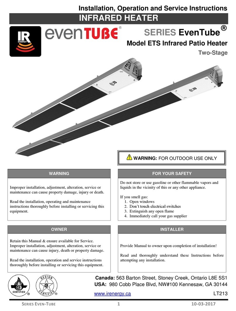
IR Energy ETSV Series Manual

LT284 Series ETSV 1Jan. 30, 2020
Installation, Operation and Service Instructions
INFRARED HEATER
WARNING
FOR YOUR SAFETY
Improper installation, adjustment, alteration, service
or maintenance can cause property damage, injury
or death.
Read the installation, operating and maintenance
instructions thoroughly before installing or servicing
this equipment.
Do not store or use gasoline or other flammable vapors
and liquids in the vicinity of this or any other appliance.
If you smell gas:
1. Open windows
2. Don’t touch electrical switches
3. Extinguish any open flame
4. Immediately call your gas supplier
OWNER
INSTALLER
Retain this Manual & ensure available for Service.
Improper installation, adjustment, alteration, service
or maintenance can cause injury, death or property
damage.
Read the installation, operation and service
instructions thoroughly before installing or servicing
this equipment.
Provide Manual to owner upon completion of
installation! Read and thoroughly understand these
Instructions before attempting any installation.
Canada: 563 Barton Street, Stoney Creek, Ontario L8E 5S1
USA: 315 N Madison Street, Fortville, IN 46040
www.irenergy.ca
Series ETSV Infrared Heater
Two-Stage

LT284 Series ETSV 2Jan. 30, 2020
CAUTION - FIRE OR EXPLOSION HAZARD
Maintain clearance to combustible constructions as further specified in this manual. Failure to do so
could result in a serious fire hazard. Heaters should not be located in hazardous atmospheres
containing flammable vapors or combustible dusts. Signs should be provided in storage areas
specifying maximum safe stacking height.
CAUTION - MECHANICAL HAZARD
This equipment expands and contracts with each operating cycle. The gas connection, suspension
hardware, and the installation itself must safely allow this movement. Failure to do so could result in
serious fire or explosion hazard.
CAUTION - FIRE OR EXPLOSIONS HAZARD
This heater is equipped with an automatic ignition device. Do not attempt to light the burner by hand.
Failure to comply could result in a serious fire and personal injury hazard.
CAUTION - MECHANICAL HAZARD
Do not use high pressure (above ½ psi, 60 mbar) to test the gas supply system with the burners
connected. Failure to do so could result in damage to the burner and its control components requiring
replacement.
CAUTION - SERVICE LIFE RISK
Do not install equipment in atmosphere containing halogenated hydrocarbons or other corrosive
chemicals. Failure to do so may lead to premature equipment failure and invalidation of the warranty.
Additionally, it is recommended that the equipment be installed with a downward slope, away from the
burner. The rate of declination should be ¼” (6mm) in height per 10’ (3m) in length to allow the start-up
condensation to drain.
CALIFORNIA PROPOSITION 65
This appliance, its related accessories and by-product of operation, contain chemicals known to the
State of California to cause cancer and birth defects or other reproductive harm. For more information
go to www.P65Warnings.ca.gov.

LT284 Series ETSV 3Jan. 30, 2020
WARNING - CARBON MONOXIDE POISONING HAZARD
Failure to follow the steps outlined below for each appliance connected to the venting system being
placed into operation could result in carbon monoxide poisoning or death. The following steps shall be
followed for each appliance connected to the venting system being placed into operation, while all other
appliances connected to the venting system are not in operation:
1. Seal any unused openings in the venting system.
2. Inspect the venting system for proper size and horizontal pitch, as required in the National Fuel
Gas Code, ANSI Z223.1/NFPA 54 or the Natural Gas and Propane Installation Code, CSA
B149.1 and these instructions. Determine that there is no blockage or restriction, leakage,
corrosion and other deficiencies which could cause an unsafe condition.
3. As far as practical, close all building doors and windows and all doors between the space in
which the appliances(s) connected to the venting system are located and other spaces of the
building.
4. Close fireplace dampers.
5. Turn on clothes dryers and any appliance not connected to the venting system. Turn on any
exhaust fans, such as range hoods and bathroom exhausts, so they are operating at maximum
speed. Do not operate a summer exhaust fan.
6. Follow the lighting instructions. Place the appliance being inspected into operation. Adjust the
thermostat so appliance is operating continuously.
7. Test for spillage from draft hood equipped appliances at the draft hood relief opening after 5
minutes of main burner operation. Use the flame of a match or candle.
8. If improper venting is observed during any of the above tests, the venting system must be
corrected in accordance with the National Fuel Gas Code, ANSI Z223.1/NFPA 54 and/or
Natural Gas and Propane Installation Code, CSA B149.1.
9. After it has been determined that each appliance connected to the venting system properly
vents when tested as outlined above, return doors, windows, exhaust fans, fireplace dampers
and any other gas-fired burning appliance to their previous conditions of use.
WARNING
Certain materials or items, when stored under the heater, will be subjected to radiant heat and could be
seriously damaged. Children and adults should be alerted to the hazards of high surface temperatures
and should stay away to avoid burns or clothing ignition. Young children should be carefully supervised
when they are in the same space as the heater. Clothing or other flammable materials should not be
hung from the heater, or placed on or near the heater.
WARNING - RESIDENTIAL DWELLINGS
Certain materials or items, when stored under the heater, will be subjected to radiant heat and could be
seriously damaged. Children and adults should be alerted to the hazards of high surface temperatures
and should stay away to avoid burns or clothing ignition. Young children should be carefully supervised
when they are in the same space as the heater. Clothing or other flammable materials should not be
hung from the heater, or placed on or near the heater.
SAFETY FEATURES
This heater utilizes an airflow switch as blocked vent shut off system. This system is designed to
prevent the operation of the appliance if a fresh air supply is blocked or if the flue exhaust is blocked. If
this system fails to operate DO NOT ATTEMPT ADJUSTMENTS. Disconnect power to the appliance
and contact a qualified service person.

LT284 Series ETSV 4Jan. 30, 2020
Contents
Contents ....................................................................................................................................................................... 4
Introduction.................................................................................................................................................................. 5
Installation Codes.................................................................................................................................................5
General Specifications................................................................................................................................................ 6
Gas Supply...........................................................................................................................................................6
Electrical Supply...................................................................................................................................................6
Flue and Outside Air Connection .........................................................................................................................6
Configurations ............................................................................................................................................................. 6
High Altitude.........................................................................................................................................................6
Dimensional Chart....................................................................................................................................................... 7
ETSV 40...............................................................................................................................................................7
ETSV 80...............................................................................................................................................................8
Components................................................................................................................................................................. 9
Heater Components for ETSV 40 ........................................................................................................................9
Heater Components for ETSV 80 ......................................................................................................................11
Installation Requirements......................................................................................................................................... 13
Clearance to Combustibles................................................................................................................................13
Heater Mounting ........................................................................................................................................................ 14
Rigid Surface Mounting......................................................................................................................................14
Installation Instructions ............................................................................................................................................ 16
Installation Sequence ETSV 40 .........................................................................................................................16
Installation Sequence ETSV 80 .........................................................................................................................31
Gas Piping .................................................................................................................................................................. 52
Installation / Code Requirements .......................................................................................................................52
Electrical Wiring ........................................................................................................................................................ 53
General Requirements.......................................................................................................................................53
Multiple Heater Wiring (Thermostat) ..................................................................................................................54
External Wiring Options (Outdoor Installation Only) ..........................................................................................55
Multiple Heater Wiring (Switch P/N EE020).......................................................................................................56
Vented Operation....................................................................................................................................................... 57
General Requirements .......................................................................................................................................57
Un-Vented Operation .........................................................................................................................................57
Vented Operation ...............................................................................................................................................58
Horizontal Venting ................................................................................................................................... 58
Vertical Venting ..................................................................................................................................................58
Common Vertical Venting ..................................................................................................................................58
Combustion Air Supply (Optional)......................................................................................................................59
Outdoor Installation ............................................................................................................................................60
Lighting & Shutdown Instructions........................................................................................................................... 60
Lighting...............................................................................................................................................................60
Shut Down..........................................................................................................................................................60
Maintenance & Trouble Shooting ............................................................................................................................ 61
Troubleshooting Chart .............................................................................................................................................. 62
Replacement Parts List............................................................................................................................................. 63
Warranty ..................................................................................................................................................................... 64

LT284 Series ETSV 5Jan. 30, 2020
Introduction
IR Energy is a company in the infrared heating industry founded on the principles of product quality and customer
commitment. Quality commitments are evidenced by superior design, a regard for design detail and an upgrade of
materials wherever justifiable. Customer commitment is apparent through our ready responses to market demands
and a never ending training and service support program for and through our distributor network. IR Energy offers its
20 years of infrared expertise in a cost effective unitary heater design as culmination of that commitment. Series ETSV
models are low intensity infrared heaters that are easy to install and maintain, and which were engineered with
significant input from our customers. They are designed to provide economical operation and trouble-free service for
years to come.
Important
These instructions, the layout drawing, local codes and ordinances, and applicable standards such as to gas piping
and electrical wiring comprise the basic information needed to complete the installation, and must be thoroughly
understood along with general building codes before proceeding.
Only personnel who have been trained and understand all applicable codes should undertake the installation. IR
Energy Representatives are Factory Certified in the service and application of this equipment and can be called on
for helpful suggestions about installation.
Installation Codes
Installations must comply with local building codes, or in their absence, the latest edition of the national regulations and
procedures as listed below.
General Installation and Gas Codes
Heaters must be installed only for use with the type of gas appearing on the rating plate, and the installation must
conform to the National Fuel Gas Code, ANSI Z223.1/NFPA 54 in the USA and CSA B149.1 and B149.2 Installation
Codes in Canada.
This heater is approved for indoor and outdoor installation.
Public Garage Installation
Installation in public garages must conform to the Standard for Parking Structures, NFPA-88A or Standard for Repair
Garages, NFPA 88B, in the USA and CSA B149.1 and B149.2 Installation Codes in Canada.
Parking Structures
Technical requirements are outlined in ANSI/NFPA 88B (USA)
Gas Supply Lines
Gas supply pipe sizing must be in accordance with the National Fuel Gas Code, ANSI Z223.1/NFPA 54 in the USA
and CSA B149.1 and B149.2 Installation Codes in Canada. 1/8” NPT plugged tap must be installed in the gas line
connection immediately upstream of the burner farthest from the gas supply meter to allow checking of system gas
pressure.
Electrical
All heaters must be electrically grounded in accordance with the National Electric Code, ANSI/NFPA 70 in the USA,
and the Canadian Electric Code, CSA C22.1 in Canada, and must comply with all local requirements.
Venting
Refer to the National Fuel Gas Code, ANSI Z223.1/NFPA 54 in the US and CSA B149.1 and B149.2 Installation Codes
in Canada for proper location, sizing and installation of vents as well as information on clearance requirements when
penetrating combustible walls for venting purposes.

LT284 Series ETSV 6Jan. 30, 2020
General Specifications
Gas Supply
Inlet Pressure
Natural Gas
Propane Gas
Minimum:
5.0” W.C.
11.5” W.C.
Maximum:
14.0” W.C
14.0” W.C.
Manifold Pressure
Natural Gas
Propane Gas
ETSV 40, ETSV 80
High Rate:
3.3” W.C.
10.2” W.C.
Low Rate:
1.5” W.C.
4.2” W.C.
Inlet Connection
Natural Gas
Propane Gas
½” Female NPT
½” Female NPT
Electrical Supply
120 VAC 60Hz. 1Amp: 36” Cord with grounded 3 prong plug.
Flue and Outside Air Connection
4" O.D. male connection for flue adapter and outside air (optional) provided at the heater
Configurations
Natural gas
ETSV 40
ETSV 80
Heat Input
BTU/hr
38,500
80,000
Partial Heat Input
BTU/hr
23,000
50,000
Propane
ETSV 40
ETSV 80
Heat Input
BTU/hr
38,500
79,000
Partial Heat Input
BTU/hr
23,000
49,000
High Altitude
When installing this appliance over 4500 ft. above sea level in Canada, the appliance must be properly de-rated and
installed according to local codes. In the absence of local codes the appliance must be de-rated in accordance with the
most recent CSA - B149 code. In the United States for installations over 2000ft above sea level the appliance must be
installed in accordance with the Current National Fuel Gas Code, ANSI Z223.1/NFPA 54. High altitude conversion kits
are available, contact manufacturer for more details.

LT284 Series ETSV 7Jan. 30, 2020
Dimensional Chart
ETSV 40
Note: All dimensions are in inches.

LT284 Series ETSV 8Jan. 30, 2020
Dimensional Chart
ETSV 80
Note: All dimensions are in inches.

LT284 Series ETSV 9Jan. 30, 2020
Components
Heater Components for ETSV 40
Burner Head
(with Service Cover)
5/16 Nut
5/16 Lock Washer
Gasket
QTY (4)
QTY (4)
QTY (1)
#8-32 x 3/8”
Screws
QTY (70)
Grill
QTY (1)
Burner
Hanger
QTY (1)
Vent
Hanger
QTY (1)
Exhaust Grill
QTY (1)
Exhaust Cover
QTY (1)
Exhaust Support
QTY (1)
Spacer
1/4”x 1/8”
QTY (8)
Canopy
QTY (1)
#8-32 x 3/8”
Machine Screws
QTY (2)

LT284 Series ETSV 10 Jan. 30, 2020
Burner Head
Reflector
QTY (1)
10’ Flanged Tube
QTY (1)
Primary Reflector 111”
QTY (1)
Deco-Grille
60” QTY (1)
51” QTY (1)
Deco-Grille
Supports
QTY (1)
Baffle
QTY (1)
Exhaust Reflector
QTY (1)

LT284 Series ETSV 11 Jan. 30, 2020
Components
Heater Components for ETSV 80
Burner Head
(with Service Cover)
5/16 Nut
5/16 Lock Washer
Gasket
QTY (4)
QTY (4)
QTY (1)
#8-32 x 3/8”
Screws
QTY (70)
Grill
QTY (1)
Burner
Hanger
QTY (1)
Middle
Hanger
QTY (1)
Vent
Hanger
QTY (1)
Exhaust Grill
QTY (1)
Coupling
QTY (1)
Exhaust Cover
QTY (1)
Exhaust Support
QTY (1)
Spacer
1/4”x 1/8”
QTY (8)
Canopy
QTY (1)
#8-32 x 3/8”
Machine Screws
QTY (2)

LT284 Series ETSV 12 Jan. 30, 2020
Burner Head
Reflector
QTY (1)
10’ Extension Tube
QTY (1)
10’ Flanged Tube
QTY (1)
Primary Reflector 119”
QTY (1)
Secondary Reflector 111”
QTY (1)
Deco-Grille
60” QTY (3)
51” QTY (1)
Deco-Grille
Supports
QTY (3)
6’ Baffle
QTY (1)
6’ Baffle
QTY (1)

LT284 Series ETSV 13 Jan. 30, 2020
Installation Requirements
Clearance to Combustibles
A general clearance of 18” (0.5 m) in every direction is recommended for servicing around each Burner. This
ensures adequate air flow in and around the Heating System.
In addition to this it is very important to observe the minimum clearance to combustibles at all times to avoid
any possibility of property damage or personal injury.
Table below lists the minimum clearance to combustible materials for various installation configurations. Additional
clearance may be required for glass, painted surfaces and other materials which may be damaged by radiant or
convective heat.
Combustible materials are considered to be wood, compressed paper, plant fibres, plastics, Plexiglas or other
materials capable of being ignited and burned. Such materials shall be considered combustible even though flame-
proofed, fire-retardant treated or plastered.
Adequate clearance to sprinkler heads must be maintained. NOTE: Sprinkler head heat fuse link performance may
alter with age.
The stated clearance to combustibles represents a surface temperature of 90°C (50°F) above room temperature.
Building materials with low heat tolerance (such as plastics, vinyl siding, canvas, tri-ply, etc.) may become subject
to degradation at lower temperatures. It is the installer’s responsibility to ensure that adjacent materials are
protected from degradation.
Reflector Configurations
Dim
ETSV 40
ETSV 80
A
B
C
D
3”
18”
54”
18”
2"
26"
64"
26"
A
B
C
D
4”
4”
46”
34”
4"
6"
58"
36"
A
B
C
D
6”
4”
44”
38”
4”
4”
58”
50”
A
6”
6”
B
16”
16”
Vent End
End
18”
18”
Horizontal
30 Deg.
45 Deg.

LT284 Series ETSV 14 Jan. 30, 2020
Heater Mounting
The heater can be mounted in a variety of ways, using a combination of chains or mounting brackets. It is critical that
the heater is prevented from swaying and putting stress on the gas connection. Also, be sure to check local codes for
seismic bracing requirements for outdoor heating equipment.
Note: Minimum mounting height is 7’ in Canada and 8’ in the US.
Rigid Surface Mounting
In order to allow for lateral tubing expansion in the case of rigid mounting, the burner hanger must be free and the rest
of the hangers must be fixed, as outlined below.
ETSV 40
ETSV 80
Note: It is crucial to position the free hanger such that the heater may expand in the direction of the
burner. See diagram below for more details.
Burner Hanger
FREE
Middle Hanger
FIXED
Vent Hanger
FIXED
Burner
Hanger
Expansion
FREE
FIXED
Burner Hanger
FREE
Vent Hanger
FIXED

LT284 Series ETSV 15 Jan. 30, 2020
For ceiling and wall mount applications, optional hangers are available:
Fixed
Free
Wall Mount
CR139L/R
CR205
CR182L/R
CR221
Ceiling Mount
CR135
CR206
CR134
CR207
CR181L/R
CR222
CR223L/R
CR224

LT284 Series ETSV 16 Jan. 30, 2020
Installation Instructions
Installation Sequence ETSV 40
Generally, there is no unique sequence for installation of the burner or heat exchanger. A review of the job site will
usually indicate a logical installation order. However, time and expense can be saved if installation is begun at the
most critical dimension, watching for interference from overhead beams etc.
It is RECOMMENDED to follow the assembly sequence shown in the following pages for free hanging installation.
Step 1:
90”
Pipe Stand

LT284 Series ETSV 17 Jan. 30, 2020
Step 2:
10’ Flanged Tube
*Face the Tube’s weld-seam
Downwards at a 6 o’clock position.
Burner Hanger
Step 3:

LT284 Series ETSV 18 Jan. 30, 2020
Step 4:
Vent Hanger
Note correct orientation. Do NOT
tighten nuts on U-bolt.
Step 5:
Orient notches towards
Burner Hanger
Primary Reflector
Burner Hanger

LT284 Series ETSV 19 Jan. 30, 2020
Step 6:
Slide Reflector and Burner
Hanger against flange.
Step 7:
#8-32 x 3/8” screws only.
No spacers!
#8-32 x 3/8” screws
AND spacers. See
details below.
Spacers MUST be
installed as shown
!
Install ONLY these four.

LT284 Series ETSV 20 Jan. 30, 2020
Step 8:
Exhaust Cowling
Install ONLY these four.
Remove Service Cover
From Burner Head.
Step 9:
Other manuals for ETSV Series
1
This manual suits for next models
1
Table of contents
Other IR Energy Heater manuals
Popular Heater manuals by other brands

ARDESTO
ARDESTO CHK-2000MW user manual

Aspira
Aspira CH 7000 Series User instructions

Heinner
Heinner HCH-L1500RD instruction manual

Harvia
Harvia sentiotec HWO-035NS-P Instructions for installation and use

Kooper
Kooper 2191365 User instructions

Xtreme Power
Xtreme Power 96958 Owner's manual and safety instructions