P/N: 058-70007-001 Printed in Taiwanwww.irtec.com
This product may be covered by one or more U.S. patents or patent applications.
Please visit www.irtec.com for more information.
OVERVIEW
The BDT-700 series is a 2-pole dual technology low voltage
wall switch sensor designed to fit in a standard NEMA wall box
for automatic lighting control. This state-of-the-art wall switch
sensor combines digital Passive Infrared (PIR) and advanced
High Frequency Doppler (HFD) sensing technologies into
an aesthetically pleasing housing to provide excellent
occupancy/vacancy sensing performance within its 180° field
of view detection range.
The BDT-700Sx contains two isolated dry contacts, and two
push buttons, for controlling two lighting loads or circuits
independently via the connected Power Packs or BMS. A dual
color LED indicates the status of sensor detection, GREEN for
PIR and BLUE for HFD. Pressing the push-button will change
the state of relay contacts manually. The sensor provides
typical occupancy sensing (Auto-ON, Auto-OFF) control
on pole-1 and vacancy sensing (Manual-ON, Auto-OFF)
control on pole-2. Different control modes of each pole can
be programmed via DIP switch settings. Presentation Mode
(PM) allows the occupant to switch off the load as desired by
pressing the specific push-button. The load will remain off if
motion is detected before the time delay elapses. Pressing
the push-button again will turn the load back ON and the
sensor will operate as per sensor setting. If no motion has
been detected and the time delay expires, sensor will return
to normal operation and turn on the load with the next sensed
motion.
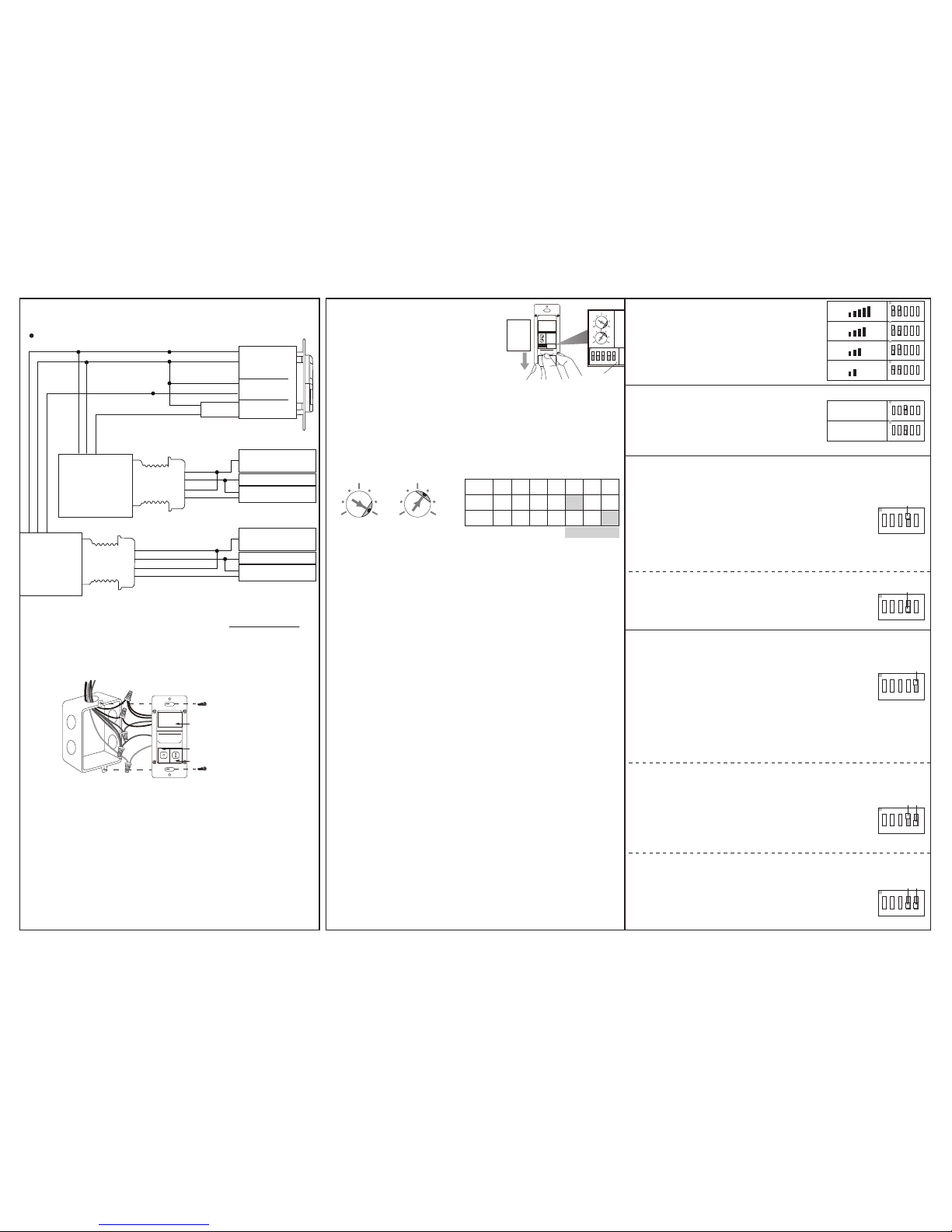
INSTALLATION NOTES
SPECIFICATIONS
Low Voltage Dual-Tech Wall Switch
INSTALLATION INSTRUCTIONS
BDT-700 Series
Power input
Current drain
Sensing technology
Control output
Contact rating
Detectable speed
Mounting height
Ambient light level
Delay time setting
Op. humidity
Op. temperature
Dimensions
Detection coverage
12~24VDC ± 5%
10/40 mA, 24VDC @vacant/occupied
Digital PIR & High Frequency Doppler
2 x form A relay, isolated dry contact
Max. 2A @30VDC, isolated
1~10 ft./sec. (0.3~3 m/sec)
3 ~ 5 ft. (90~150 cm) above the floor
Major motion - 30 ft x 40 ft (W x L) @4 ft high
Minor motion - 20 ft x 20 ft (W x L) @4 ft high
7 levels, from dark to 24 Hr. (ALS disabled)
T/1’/3’/5’/10’/20’/30’, T=10 sec. for testing
Max. 95% RH, non-condensate
-40°F ~ 131°F (-40°C ~ 55°C)
4.13”H x 1.77”W x 1.65”D (w/mounting plate)
INDOOR USE ONLY
Utilisation a L'interieur Uniquement
The PIR sensor is more sensitive to the movements
“crossing” the detection zones than “toward” or “away”
it. To obtain better sensitivity, ensure the sensor to have
clear field of view for the occupant’s motion within the
desired detection coverage.
In general, the HFD sensor has better sensitivity to the
minor motions than the PIR sensor. The HFD sensor
could possibly detect the movements out of sight
through non-metallic partition or enclosure. If so,
reduce the HFD sensitivity to prevent unwanted
triggering.
The sensor should be mounted within the specified
mounting height to achieve optimal performance.
Do NOT mount the sensor directly above or nearby a
heat source, or where unintended motion (e.g. hallway
traffic) will be “seen” by the sensor.
1.
2.
3.
4.
DETECTION COVERAGE
40’
Top view
Side view
4’ 7’
30’
40’
Minor motion
20’
20’
Major motion
180°, 30 ft x 40 ft (W x L)
Turn power OFF at circuit breaker before installing Power Pack
or Sensors.
Do NOT touch the square window of infrared sensor under the
lens assembly.
WARNING:
Do Not Install To and/or Cover a Junction Box Having Class 1, 3 or
Power and Lighting Circuits
Class 2 Device Wiring Only – Do Not Reclassify and Install as Class 1,
3 or Power and Lighting Wiring
Coupez l'alimentation au disjoncteur avant d'installer Power
Pack ou capteurs.
Ne PAS toucher la fenêtre carrée de capteur infrarouge sous
l'ensemble de l'objectif
AVERTISSEMENT :
Classe 2 Câblage de périphériques Seulement - Ne PAS reclasser et
installer Classe 1, 3 ou alimentation et circuits d'éclairage
WARNING & CAUTION
AVERTISSEMENT & PRUDENCE