IRC POWER SLIDE CONTROL User manual

1 di 18
PRESENTS
POWER SLIDE CONTROL
The Power Slide Control is our latest high performance creation; we put down an
enormous amount of time and engineering into it, to create an effective and reliable
product. It is developed b racers for racers.
The Power Slide Control is an electronic s stem able to reduce the rear wheel slide off
during accelerations and constant throttle. It is not able to reduce the slide off during the
braking phase.
The s stem is composed b an ECU and 2 velocit sensors put on front and rear wheels.
The variation of the difference between front and rear wheel velocities is continuousl
monitored in order to understand if the rear wheel is sliding off or not. The Power Slide
Control is able to understand if the bike is on straight, or in a slow turn or in a fast turn, and
consequentl acts.
Please read the installation
instructions carefull before
using our PSC. Make sure
ou full understand and
agree with disclaimer
before using this product.

2 di 18
DISCLAIMER
The Power Slide Control is intended for use on a closed circuit onl . The Power Slide Control
is not road homologated. The Power Slide Control is not a safet component. Sliding losses
mean possible driver crash; the Power Slide Control aim is onl to support the driver in this
phase, reducing or deleting, if possible, the sliding conditions. The Power Slide Control
does not guarantee the possibilit of sliding off and driver’s crash. It is not guaranteed that
the Power Slide Control avoids crash of the bike with possible damage to the bike, driver
or third parts.
The Power Slide Control allows to user several settings both during installation and use. A
wrong setting could affect, partiall or full , the s stem effectiveness. Even the wrong
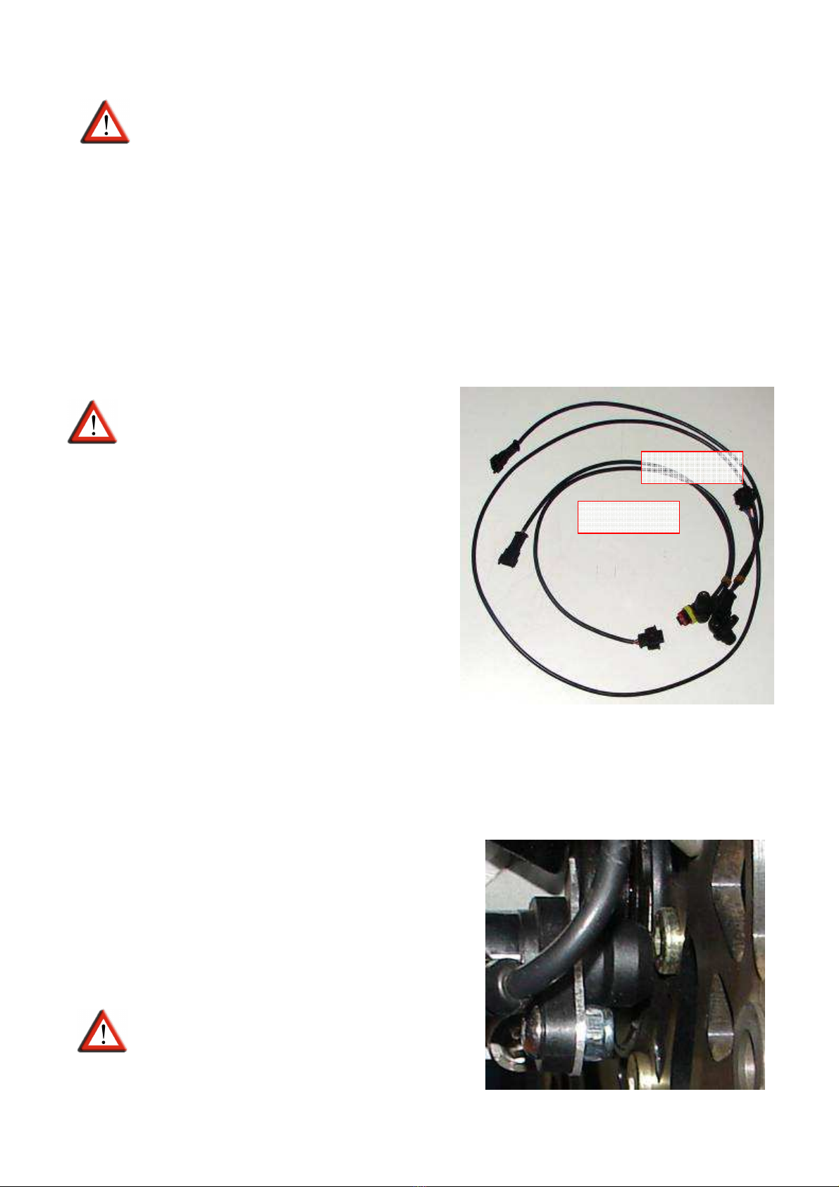
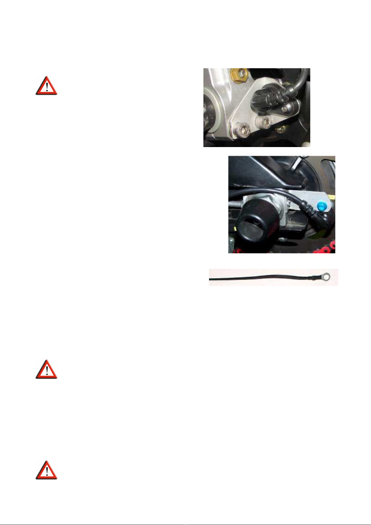
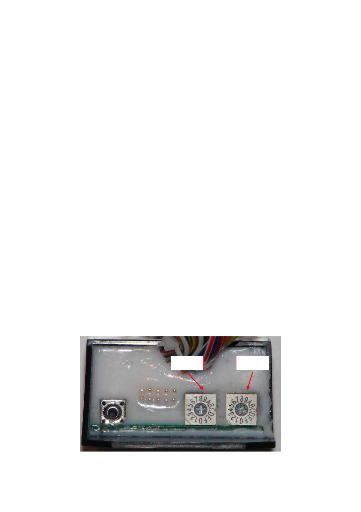
fitment of the front and rear sensors could affect the s stem performances. Take particular
care to chain adjustment operation that could misalign the rear sensor if not properl
bracket.
The use of this product is at the sole discretion of the user. The manufacturer of this
product is not liable for an kind of damage or injur caused to the operator, vehicle, or to
third parts.
The Power Slide Control installation must be done according to following instructions. It’s
strongl suggested to test the Power Slide Control and the bike after the installation.
WARNING:
Each s stem modification, both hardware and software and
harness or single components, could affect the s stem functionalit with of
damage or injur caused to the operator, vehicle, or to third parts and delete the
product warrant .
Installation must be done carefull following these instructions. Si consiglia di testare il
Power Slide Control. It’s strongl recommended to test the product and the bike after the
installation.
WARNING
: Installation is a ver critical operation for s stem effectiveness. Be
sure that it is done b clever and specialized personnel.
WARNING
: Even in the case that the s stem is been installed and set b
specialized personnel, the end user must follow all tests according to the
procedure describe in the following paragraph 6th (Pre use tests).
The PSC is a race use onl product so the warrant on its parts and components is onl
ONE ear from date of purchase.
This manual is issued on March. 5
th
2010 in Rev. 1.1. It’s end user responsibilit periodicall
visit the website www.irccomponents.com in order to check new releases of manual and
software. The eventual re-programming will be done free of charge except the shipment
cost.

3 di 18
WARNING
: Although the PSC ECU are all identical, the software could be
different in function of application (engine t pe or connection t pe – injectors or
ignition). Each single ECU has a label indicating the diagnosis and cut software version.
Check on the website if it is matching with our engine and installation t pe.
INSTALLATION MANUAL
Installation must be done onl b clever personnel. Do not proceed with installation if not
expert and able to do.
1. Sensors installation
WARNING
: Take maximum care to
sensors installation.
2 Speed sensors are included in the kit.
The are Automotive products, with the
advantage of a relaible reading but don’t allow
a fine adjustment of the sensor-target distance.
The sensors’ brackets must be stiff and ver well
done. If necessar to change the sensor-target
distance, use spacers avoiding brackets bend.
Connect sensors to linking wires.
The longest sensor-linking wire must be
positioned to the front wheel. Connect the
shortest one to the rear wheel.
The s stem properl works when the front and rear sensors read from minimum 3 to
maximum 6 pulses. These must be equall spaced. Its strongl recommended use the max
number of pulses possible.
Fit the sensors being sure that the do not read
holed screw heads that could false the signals. If the
substitution of bolts with full head is not possible, put
the sensors at the sides of the heads.
Be sure that the nuts are read b a magnet.
WARNING
Put the sensor at a distance
around 3÷5mm from the target.
Rear
Front

4 di 18
WARNING
: Sensors’ brackets must be
stiff, welll fastened and not bending.
Take care on rear sensor’s bracket: during the chain
adjustment operation, the rear sensor must be aligned
with his target. A disaligment could cause a wrong
signal read, with impact on PSC s stem operation.
2. Ground onne tion
Connect the ground wire to the frame.
3. Coils/Inje tors onne tion
The PSC cut up to 2 coils or injectors.
On 3÷4c linders engines connect the PSC to 2 c linders; on twin c linders connect the
s stem onl to one c linder.
WARNING
: Cut on coils affects emissions and catal ser’s life. In order to avoid
these damages, in case a catal ser is fitted, connect the s stem to the injectors.
3.1. COILS CONNECTION
The PSC is plug&pla for the most common sport bikes.
Mostl all bikes have 2 wires for each coil: positive that is coming from batter or other
+12v line and negative pulse wire that is coming from the ECU.
WARNING
: on latest Yamahas ou could find both wires positive. Consider

5 di 18
“real” positive the highest voltage one.
Refer to the following proper paragraph
3.1.1. JAPANESES SPORTS BIKE (Coils on spark plugs) & TRIUMPH
Unplug coils and determine the positive wire.
If, at the order ou specif the bike, the harness will be supplied with end line connectors
alread plugged; directl connect to the coils and jump this section.
Look from the harness at a coil; if the +12v (common colour) wire is on the right hand side,
it is a DENSO ignition s stem.
T pical examples of Denso coils are: Suzuki GSXR 600, GSXR1000 e Ha abusa, Honda
CBR600RR and CBR10000RR.
In this case connect harness according to following picture:
If +12v are on the left, is is a MITSUBISHI ignition s tem (coils branded with 3 leaves ).
T pical examples of Mitsubishi coils are: Yamaha R6 and R1, Kawasaki ZX6R and ZX10R,
Triumph.
In this case connect harness according to following picture:

6 di 18
To connect the harness-connectors act as described:
Insert male pins on the small connector. Close it with the ellow plastic ke .
Insert female pins on the big connector. Close it with the ellow plastic ke .
3.1.2. Engines with oils not integrated on plug sparks:

7 di 18
Locate the coils and how man the are. Use the proper number of PSC connectors
following this order: green/black-gre , green/red-orange. Cut off the PSC plug & pla
connectors. Unplug the connectors of the coils; locate pulse wires (usuall the are
different colour for each coil), cut it. Connect the ECU side with the green/black wire and
the gre wire to the coil wire.
Connect the red wire to ignition switch controlled +12v, a tail light suppl wire is preferred
since it is powered continuousl .
On 3 and 4 c linders engines take another coil harness. Unplug the connectors of the coils;
locate pulse wires (usuall the are different colour for each coil), cut it. Connect the ECU
side with the green/red wire and the orange wire to the coil wire.
Seal off the not used wires.
3.1.3. CONNECTIONS FOR DUCATI, APRILIA, MV
WARNING
: Specific ECU programming could be necessar if not specified this
application at the order.
WARNING
: On twins use onl the connector with green/black-gre wires.
Use the proper harness (specif on order).
Connect the red wire to ignition switch controlled +12v, a tail light suppl wire is preferred
since it is powered continuousl .
OR:
These bikes have 3 wires for each coils: +12v common colour for each coil, negative
common colour for each coil and pulse wire different colour for each coil.
Take the PSC connector with red, green/black and gre wire. Cut harnesses. locate pulse
wire (usuall the are different colour for each coil), cut it. Connect the ECU side with the
green/black wire and the gre wire to the coil wire.
Connect the red wire to ignition switch controlled +12v, a tail light suppl wire is preferred
since it is powered continuousl .

8 di 18
MV and RSV4: , take another coil harness. Unplug the connectors of the coils; locate pulse
wire (usuall the are different colour for each coil), cut it. Connect the ECU side with the
green/red wire and the orange wire to the coil wire.
Seal off the not used wires.
S heme for Du ati 999 and other CDI ignition: the gre blue, and gre brown are the pulse
wires, one to each coil. Changes colour to red close to coil; cut the red pulse wire after
the black insulation is stripped about 40mm. Connect the red wire from the coil with the
PSC gre and the other side with PSC green/black.
Seal off the not used wires.
3.1.4. KTM SuperDuke and RC8
WARNING
: Specific ECU programming could be necessar if not specified this
application at the order.
Use the proper harness (specif on order) OR refer to above 3.1.1, following Denso scheme
and connecting the PSC to onl one c linder.
3.1.5. Aprilia and twin spark engines:
WARNING
: Specific ECU programming could be necessar if not specified this
application at the order.
follow the same colour wires till the become one. Take the PSC connector with red,
green/black and gre wire. Cut harnesses. Connect the ECU side with the green/black
wire and the gre wire to the coil wire.
3.2 INJECTORS CONNECTION
WARNING
: Specific ECU programming could be necessar if not specified this
application at the order.
The PSC has onl 2 exits for the power cut
On twin c linders cut onl one c linder
On 3-4 c linders cut, if possible, 2 of them.
In case of twin injectors, cut both injectors from same c linder.
WARNING
: connection of 2 injectors to the same PSC wire, could cause the
ECU warning light switching on.

9 di 18
Use the proper number of PSC connectors following this order: green/black-gre ,
green/red-orange. Cut off the PSC plug & pla connectors. Unplug the connectors of the
injectors; locate pulse wire (usuall the are different colour for each coil), cut it. Connect
the ECU side with the green/black wire and the gre wire to the injector wire.
Connect the red wire to ignition switch controlled +12v, a tail light suppl wire is preferred
since it is powered continuousl .
If necessar take another injector’ harness. Unplug the connectors; locate pulse wires
(usuall the are different colour for each coil), cut it. Connect the ECU side with the
green/red wire and the orange wire to the injector wire.
Seal off the not used wires.
3.2.1. MV
Use the proper harness (specif on order).
Disconnect one injector connector.
USING THE CONNECTORS INCLUDED IN THE KIT, connect the GREEN/BLACK wire of PSC to
the brown 8even striped) wire of the bike, ECU side. Connect the GREY wire in the relative
side of the injector connector. Connect the residual empt positions with the wire
included in the kit.
Go to another connector.
USING THE CONNECTORS INCLUDED IN THE KIT, connect the GREEN/RED wire of PSC to the
brown 8even striped) wire of the bike, ECU side. Connect the ORANGE wire in the relative
side of the injector connector. Connect the residual empt positions with the wire
included in the kit.
4. SYSTEM SETUP
On the ECU front side there are 2 selector switches.
Pulses Ratio

10 di 18
WARNING
: Take care to the arrow direction!
First of all set up the number of “pulses” for both front and rear sensors, acting on the left
selector switch according to the following table:
FRONT REAR SETTING FRONT REAR SETTING
3 3 0 4 3 8
3 5 1 4 5 9
3 4 2 4 4 A
3 6 3 4 6 B
5 3 4 6 3 C
5 5 5 6 5 D
5 4 6 6 4 E
5 6 7 6 6 F
Then measure the circumferences of front ad rear wheels, in the center of the t re, and
make the difference between the 2 values. Set up the “Ratio” acting on the right selector
switch according to the following table:
DIFFERECE [ m] SETTING DIFFERENCE [ m] SETTING
0 - 1 0 13 8
2 - 3 1 14 9
4 - 5 2 15 A
6 - 7 3 16 - 17 B
8 - 9 4 18 - 19 C
10 5 20 - 21 D
11 6 22 - 23 E
12 7 24 - 25 F
SUGGESTION: If ou like to have a bigger sensitivit of the s stem at the high speeds, ou
can increase the “ratio” of 1 or 2 steps; if ou like a lower sensitivit at the high speed,
reduce the “ratio” of 1 or 2 steps, as per following chart.

11 di 18
WARNING
: A too high ratio set could cause PSC acting even in the straigth
and in the acceleration phase.
5. DASHBOARD INSTALLATION
Install the potentiometer, the 2 switches and the 2 leds, in the carbon plate included in the
kit. Cut it and drill according to our own requirements. Put it in a alwa s visible position ad
eas to reach b hand.

12 di 18
WARNING
: Put the dashboard taking care that the 2 leds are oriented directl
towards the driver’s e es.
Sensitivit potentiometer is positioned in order to have the s stem OFF if counter clockwise
rotated and maximum sensitivit if completel rotated clockwise, according to numbers in
the sticker. (0 OFF, 10 max sensitivit ).
In the harness with leds and potentiometer, there is the
LAUNCH CONTROL switch.
It’s ON or OFF according to pictures on the right.
When Launch Control is on, the PSC control the front wheel
height,. The front wheel will rise, more or less, 20cm and,
slowl , will go down.
Suggestion for the switch positioning: LC ON towards down
(ie. The front wheel must be down) and LC OFF upward.
In the harness with coils connectors, there is the EMERGENGY SWITCH.
L.C.
OF
L.C.
ON

13 di 18
It allows to reconnect the coils as per OEM
application, completel disconnecting the PSC
s stem.
It’s ON or OFF according to pictures on the right.
Suggestion for the switch positioning: S stem ON
towards down (ie. The front wheel must be down) and
S stem OFF upward.
WARNING
: ON and OFF are referred to
pictures on the right.
6. PRE USE CHECKS
WARNING
: If an of the following tests his not passed, DO NOT USE THE SYSTEM
and contact our technical department. Disconnect the PSC through the proper
emergenc switch and disconnect the PSC from the bike.
Switching on the bike, the PSC red and green leds must flash. Otherwise the connection
to coils is not correct. Therefore refer to instruction at the above paragraph 3.
Check that, positioning the potentiometer at zero sensibilit (complete counter clockwise
rotation) the green led is flashing in constant manner, like an arrow light
Check that, positioning the potentiometer at maximum sensibilit (complete clockwise
rotation) the green led is flashing quickl 3 times.
Set Ratio on “F”, Pulse on “C” and Sensitivit on maximum. As soon the bike is running
above 10Km/h the PSC must cut the power.
If test has been passed, set Ratio on “F”, Pulse on correct value and Sensitivit on
maximum. Drive the bike. The PSC will cut power at the minimum traction loss.
If test has been passed, set Ratio and Pulse on correct values and Sensitivit to maximum.
WARNING
: Although the installation could seem well done, alwa s make sure
to have full confidence that the s stem properl works at all speeds.
DO NOT TEST THE PSC IN OPEN TRAFFIC ROAD but in circuit, alwa s wearing safet
wear like, helmets, gloves, boots, rear protector, racing leather suit)
Test the s stem at low speed.
T.C.
O
F
T.C.
O
N

14 di 18
Test the bike in straight with dirt ground. The PSC will cut power at the minimum traction
loss.
Switch the Launch Control ON. Test the s stem, with the highest possible gear that allows
the front wheel rise due to power and not in first gear. The PSC will work carr ing the front
wheel again on the ground.
Test the s stem in a corner, never 100% full throttle. The PSC must cut the power.
Repeate the above tests at higher speed, proceeding step b step
.
Reduce Sensitivit , step b step, till PSC act as preferred.
WARNING
: Remember that “0” position of the potentiometer, ie. complete
counter clockwise rotation, means s stem OFF not acting.
7. DIAGNOSIS SYSTEM AND ERROR LED (RED)
The PSC ha san autodiagnosis s stem that continuousl monitors the status of hardware,
software and connections. In case of anomal , the red led is switching on.
WARNING
: In case red led is switching on, immediatel disconnect the PSC
acting on emergenc switch. DO NOT CONTINUE TO USE THE PSC UNTIL THE
TROUBLE IS SOLVED. Stop the bike as soon possible and ph sicall disconnect
the ECU.
SWITCH OFF THE ENGINE WITHOUT SWITCHING OFF POWER TO THE PSC (i.e. do not switch
off the ke ).
Push the diagnosis button on the left side of the PSC. The red led will start to flash. Count
these flashes and check the error t pe according to the following table.

15 di 18
2 flashes Error on first c linder cut.
Check harness connections on first
c linder (Green/black-Gre wires).
Follow procedure to above 7.1.
4 flashes Error on second c linder cut.
Check harness connections on
second c linder (Green/red-Orange
wires). Follow procedure to above 7.1.
6 flashes Errore on anti spin hardware.
Check all harness and conenctions
are properl done and perfect. No
damaged wires must be..
Constant non-
stop flashes No error found.
7. 1. STATUS LED (Green)
Put the dashboard taking care that the green led is oriented directl towards the driver’s
e es.
Status led is alwa s acting according to the following table.
MOTORCYCLE
STATUS LED STATUS DIAGNOSYS TROUBLESHOOTING
Engien
running,
motorc cle
standing
3 quick lamps
Led shosw s stem is active
but on sensors imput (bike is
not running)
Pass minimum velocit
(≅10 Km/h) to activate the
s stem. If the 3 quick
lamps persist, follow 7.3
procedure.
Motorc cle
running
Flash ever
0.5 sec S stem is working properl .
If a traction loss condition
occurs and the s stem is
not acting, increase the
“Sensitivity” and,
eventuall , check the
“Ratio”.
Motorc cle
running
Fixed green
light S stem is NOT WORKING.
Switch off and on the
s stem. If the trouble
persists, DO NOT USE the
s stem and contact the
technical assistance.
Motorc cle
running No flash S stem is NOT WORKING.
Switch off and on the
s stem. If the trouble
persists, DO NOT USE the
s stem and contact the
technical assistance.
Motorc cle Quick and S stem is cutting engine If there is no real traction

16 di 18
running not constant
flash
power due to a traction loss
condition.
loss, reduce “Sensitivity”
and eventuall , check
“Ratio” and “Pulse”.
Motorc cle
running
Constant
blinking flash,
like arrow.
The s stem is OFF.
Activate the s stem
selecting a “Sensitivit ”
different from “0” moving
the knob clockwise.
7.2 Greeen light is flashing but PSC doesn’t ut.
Check that the emergenc switch is T.C. ON:
If trouble persist, proceed with Emergenc switch check:
Disconnect the 6 wa connector.
WARNING
: Switch off engine and PSC.
With amperohmeter set on 20 KΩ or diode check, check the positions of Green/Black -
Gre wires. Acting on switch the contact should pass from open to close.
In case of 2nd connector installed (green/red – orange), repeat the check on the
following positions.
T.C.ON

17 di 18
7.3 Sensors he k
To check that sensors read in proper manner, disconnect the sensor and connect the
proper tool to be ordered apart.
Switch on the PSC and SLOWLY rotate the wheel. Led must flash whenever the sensor read
the target surface.
If the check sensor’s kit is not available, take an amperohmeter set on 20v. Leaving the
sensor connected to the PSC, connect the “-“ to ground and the “+” to the blue wire of
the sensor. Switxch the PSC on and slowl rotate the wheel. The sensor will read “0v”
whenever the target surface will be read.
WARNING
: check that the target surface is read continuousl , i.e. without led
on/off or volts variations. Take care in case of reading on holed screws.

18 di 18
8. OTHER TROUBLESHOOTING
8.1 s stem acts whenever 10Km/h are reached.
S stem properl works but or rear sensors reading double check, or the front sensor is not
reading all pulses. Check sensors’ positioning.
9. TELEMETRY SYSTEMS
Connect brown/white wire to the data acquisition s stem. In case it is not used, seal it off.
Table of contents
Other IRC Motorcycle Accessories manuals