IWF 1131 8
Fault finding
Ref. No. 31-8931-0201-04/0103
Fault Check in the following order
The unit will not start 1 20 3 2 4 5 12 6
The unit will not stop 3 20 7 6 5 18
The yarn store runs out (without input sensor) 1 20 19 3 2 8 5
The yarn store runs out (with input sensor) 1 20 19 3 2 5 9
The magnet pin does not respond to the yarn release switch 1 10 5 14 12
Incorrect pick lengths 1 7 11 3 17 10 5
Excessive yarn store / overfilling 1 20 3 4 6 5 18
Stop reasons on loom display Check in the following order
Basic settings not received 4 5 12
Communication error 4 13 5 12
Yarn store not full 15
Overheated prewinder 2 16 5 12
Incorrect motor voltage 16 14 12 5
Incorrect magnet voltage 5 14 16 12
WARNING
ALWAYS TURN OFF THE MAIN SWITCH BEFORE DISCONNECTING OR CONNECTING
THE FEEDER OR ANY OF THE CIRCUIT BOARDS. ALL WORK ON ELECTRICAL COMPONENTS
SHALL BE CARRIED OUT BY A QUALIFIED ELECTRICIAN.
1. Check weaving machine display
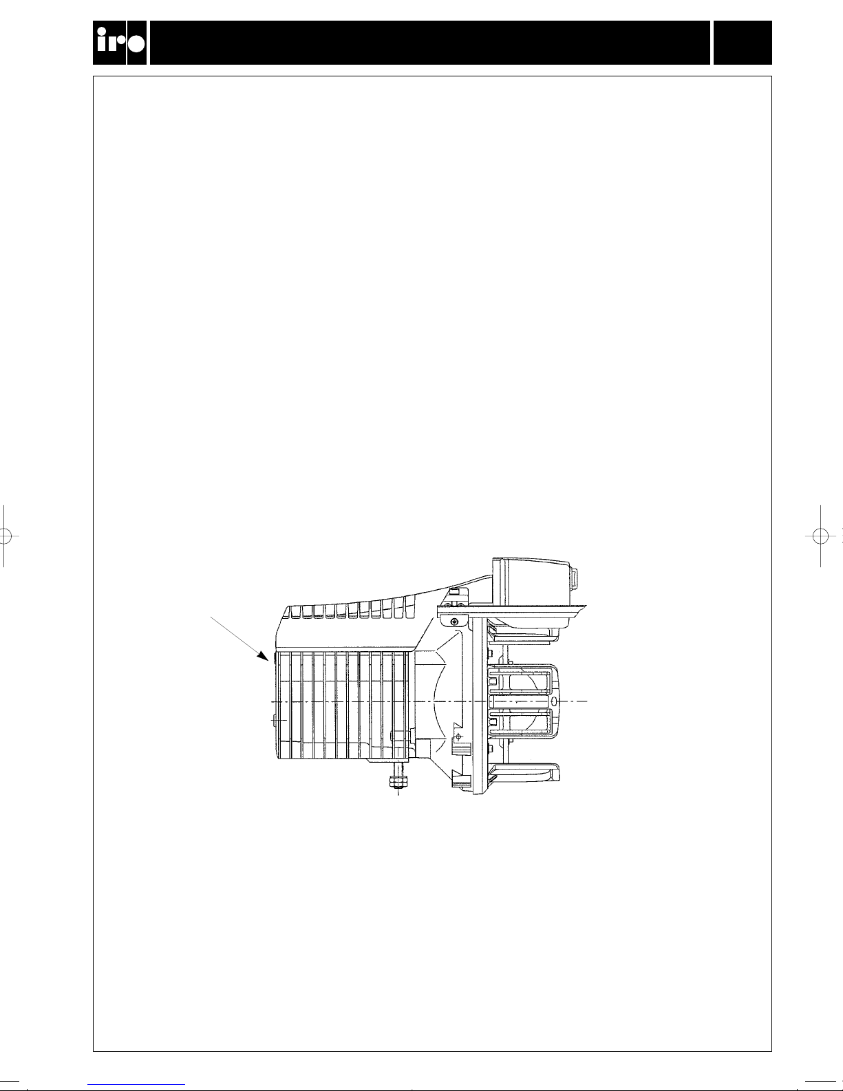
2. Check that the winding disc runs free
3. Clean sensors and spoolbody
4. Check cable connections
5. Replace motor circuit board
6. Replace yarn store sensor
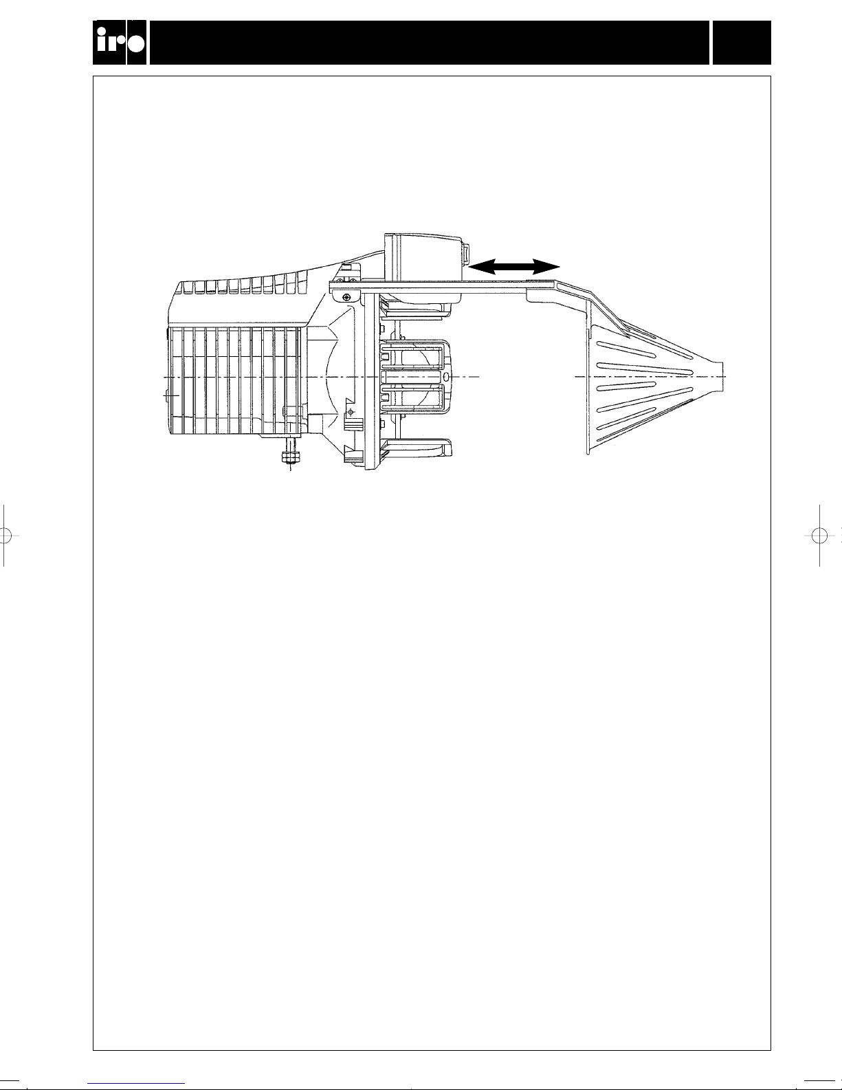
7. Check distance between magnet support and magnet finger
8. Strong yarn trapped at input side
9. Check that the weaving machine stops when the yarn breaks
10. Replace the stopper magnet
11. Check pick length setting
12. Replace interface/supply circuit board
13. Check mains supply
14. Check fuses on the interface/supply circuit board
15. Fill up the yarn store before starting the weaving machine
16. Check voltage level
17. Replace winding sensor
18. Replace wind-on sensor
19. Check whether yarn store is sufficient.
20. Reset the reserve sensor by switching off the feeder, remove the yarn store and switch on the feeder
31-8931-0201-04/0103-GB 01-01-22 12.40 Sidan 9