IRO Laser G2 User manual

IRO AB
Box 54
SE-523 22 Ulricehamn
Sweden
Tel: (Int+46) 321 297 00
Fax: (Int+46) 321 298 00
www.iroab.com
Laser G2
Operating Instructions
xxxxxxx
GB/CH
English/China
Ref. No. 28-8932-0817-01/0826

Laser G2 1
Ref. No. 28-8932-0817-01/0826
CONTENTS
INHALT
Technical specifications ............................................................................................ 2
Main parts .................................................................................................................... 3
Operating diagram ...................................................................................................... 4
Installation ................................................................................................................... 5
Mains connection ....................................................................................................... 6
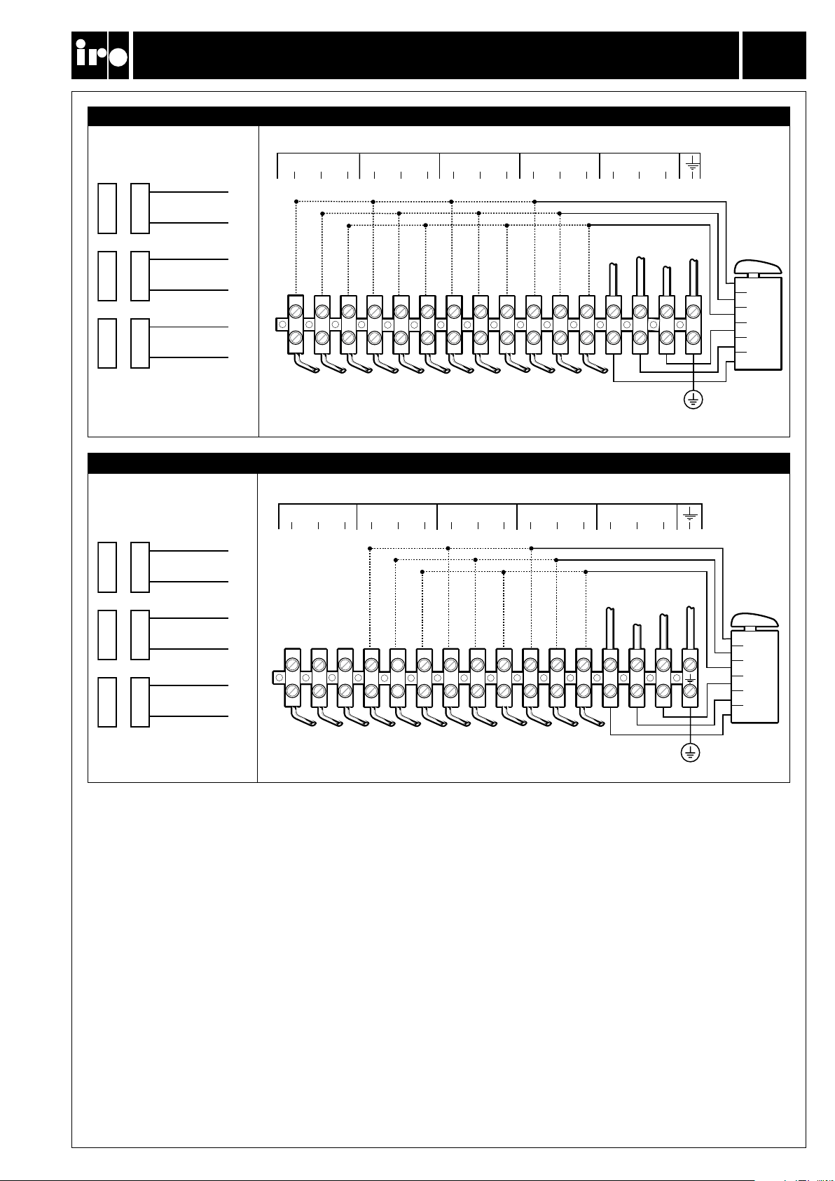
Wiring diagram ............................................................................................................ 9
Connections ................................................................................................................ 10
Jumper.......................................................................................................................... 11
Yarn control ................................................................................................................. 12
S/Z Adjustment ........................................................................................................... 14
Threading .................................................................................................................... 15
Balloon adjustment .................................................................................................... 16
CAT adjustment .......................................................................................................... 17
Sensor adjustment ..................................................................................................... 18
Maintenance ................................................................................................................ 19
Fault finding ................................................................................................................ 20
Declaration of conformity........................................................................................... 22
xxx ................................................................................................................................ 2
xx .................................................................................................................................. 3
x .................................................................................................................................... 4
x .................................................................................................................................... 5
x .................................................................................................................................... 6
x..................................................................................................................................... 9
xx .................................................................................................................................. 10
x .................................................................................................................................... 11
x .................................................................................................................................... 12
x .................................................................................................................................... 14
x..................................................................................................................................... 15
x..................................................................................................................................... 16
xx................................................................................................................................... 17
xx .................................................................................................................................. 18
xx .................................................................................................................................. 19
xxx ................................................................................................................................ 21
xx................................................................................................................................... 22
ORIGINAL LANGUAGE INSTRUCTION
IRO AB RESERVE THE RIGHT TO CHANGE THE CONTENTS OF THE USER’S GUIDE
AND TECHNICAL SPECIFICATIONS WITHOUT PRIOR NOTIFICATION.
XX.
PUTAT VEL ULLAORE DUNT IN VEL ET LA AM VENIS DEL UTE EUM QUISCILIS EXER AMETUMMY
NUMSANDIAM NONSENISIT VELIQUAT. DUI BLAOR ING EUM ZZRIT WISSI.

Laser G2 2
Max 1400 m/min
4,9 kg
Min 5° C-Max 40° C
Max 85 %
76 dB (A)
Max 5 mm
5,5 - 7 bar
Max 2,2 mm
200 - 575V 400VA
3,3 kg
Ref. No. 28-8932-0817-01/0826
Technical specifications • Technische Spezifikation
Power Supply • Stromversorgung
Max T 10A
Fuse/ Zicherung
WARNING!
CAUTION MUST BE TAKEN IN THE CLOSE VICINITY OF THE FEEDER AS IT CONTAINS MOVING PARTS THAT CAN CAUSE
INJURIES AND, IN NORMAL OPERATION, STARTS WITHOUT PRIOR WARNING.
THE POWER SUPPLY MUST BE SWITCHED OFF AT THE MAINS BEFORE ANY WORK IS CARRIED OUT ON THE FEEDER, THE
TRANSFORMER OR ANY OTHER ELECTRICAL COMPONENTS. THE FEEDER AND THE TRANSFORMER CABINET MUST BE FULLY
ASSEMBLED BEFORE THE POWER SUPPLY IS CONNECTED.
THE FEEDER AND TRANSFORMER CONTAIN ELECTRICAL COMPONENTS THAT RETAIN AN ELECTRIC CURRENT UP TO THREE
MINUTES AFTER DISCONNECTION
ALL WORK ON ELECTRICAL COMPONENTS MUST BE CARRIED OUT BY A QUALIFIED ELECTRICIAN.
THIS PRODUCT IS NOT INTENDED FOR USE IN POTENTIALLY EXPLOSIVE ATMOSPHERES OR IN ZONES CLASSIFIED ACCORD-
ING TO THE EUROPEAN DIRECTIVE 94/9/EC. PLEASE CONTACT IRO AB IF PRODUCTS FOR USE IN A POTENTIALLY EXPLOSIVE
ATMOSPHERE ARE REQUIRED.
TO COMPLY WITH C. E. REGULATIONS ONLY REPLACEMENT PARTS APPROVED BY IRO AB MAY BE USED.
THE FEEDER IS AN INDUSTRIAL PRODUCT AND THEREFORE NOT APPROVED TO USE HOUSEHOLD ENVIRONMENTS /
IN RESIDENTIAL AREAS.
WARNUNG!
IN DER UNMITTELBAREN UMGEBUNG DES VORSPULGERÄTES IST VORSICHT GEBOTEN, DA ES BEWEGLICHE TEILE ENTHÄLT,
DIE VERLETZUNGEN VERURSACHEN KÖNNEN, UND IM NORMALBETRIEB OHNE VORHERIGE WARNUNG ANLÄUFT.
VOR DER ARBEIT AM VORSPULGERÄT, AM TRANSFORMATOR ODER AN ANDEREN ELEKTROTEILEN MUSS DER STROM AM
NETZANSCHLUSS AUSGESCHALTET WERDEN. VOR DEM ANSCHLIESSEN DER STROMVERSORGUNG MÜSSEN VORSPULGERÄT
UND TRANSFORMATOR GANZ ZUSAMMENGEBAUT WERDEN.
DIE SPEICHER UND TRANSFORMER SIND MIT ELEKTRONISCHEN KOMPONENTEN BESTÜCKT DIE NOCH BIS 3 MINUTEN LANG
EINE GEWISSE ELEKTRISCHE SPANNUNG HABEN, NACHDEM DIE STROMVERSORGUNG ABGESCHALTET WURDE.
ALLE ARBEITEN AN ELEKTROTEILEN SIND VON EINEM QUALIFIZIERTEN ELEKTRIKER AUSZUFÜHREN.
DIESES PRODUKT DARF NICHT IN EINER BRANDGEFÄHRDETEN UMGEBUNG ODER GEMÄSS DEN EUROPÄISCHEN
VORSCHRIFTEN 94/9/EC EINGESTUFTEN ZONE VERWENDET WERDEN. BITTE KONTAKTIEREN SIE IRO AB, WENN SIE EIN
PRODUKT FÜR SOLCHE UMGEBUNGEN WÜNSCHEN.
GEMÄSS CE-REGELUNG DÜRFEN NUR VON IRO AB GENEHMIGTE ERSATZTEILE VERWENDET WERDEN.
DAS VORSPULGERÄT IST EIN INDUSTRIEPRODUKT UND DESHALB FÜR DIE VERWENDUNG IMPRIVATHAUSHALT NICHT GEEIGNET.
TECHNICAL SPECIFICATIONS
TECHNISCHE SPEZIFIKATION

Laser G2 3
CAT
Ref. No. 28-8932-0817-01/0826
MAIN PARTS
HAUPTTEILE
Mount
Befestigung Spool body
Spulenkörper
Winding disc
Wickelscheibe
Yarn break detector
Fadenbruchwächter Yarn store sensors
Garnlagersensoren
S/Z Switch
S/Z-Schalter ON/OFF Switch
EIN/AUS-Schalter
Indicator
Anzeigelampe
Balloon control adjuster
Ballonkontrolleinstellung
Adjustment
Einstellung
Tension ring quick-release
Spannring schnell abhebbar

Laser G2 4
+
+
TB1
TB2
S/Z
ON/OFF
P3 – P10
P1 P1 P1
P2
13,8 Ω +/- 5%
Ref. No. 28-8932-0817-01/0826
OPERATING DIAGRAM
FUNKTIONSDIAGRAMM
Motor control unit
Motorsteuereinheit
Motor
Motor
Fuse panel
Sicherungstafel
Mains supply
Hauptanschluss
Transformer
Transformator
Machine stop signal
Maschine-Stopp-Signal

Laser G2 5
Ref. No. 28-8932-0817-01/0826
INSTALLATION
INSTALLATION
NOTE
Condensation can form on the weft feeder when it is moved from the cold environment of the warehouse
to the warmer environment of the loom room. Make sure that the feeder is dry before switching it on.
ACHTUNG
Kondenswasser kann sich bilden, wenn der Fadenspeicher aus der kalten Umgebung des Lagers in den wärmeren
Webraum gebracht wird. Bitte darauf achten, dass das Gerät trocken ist, bevor es eingeschaltet wird.
The unit should not be mounted directly on
the weaving machine.
Die Einheit darf nicht direkt an der
Webmaschine montiert werden.
Use a separate oor stand.
Separates Gestell verwenden.
Ensure that the mount screws are correctly
tightened.
Sicherstellen, daß Befestigungsschrauben
richtig angezogen sind.

Laser G2 6
L1 L2 L3
Z S
Ref. No. 28-8932-0817-01/0826
MAINS CONNECTION
NETZANSCHLUSS
IMPORTANT!
TURN OFF THE MAIN SWITCH BEFORE ANY WORK IS CARRIED OUT ON THE ELECTRICAL CIRCUIT.
WICHTIG!
HAUPTSCHALTER VOR DER ARBEIT AM STROMKREIS AUSSCHALTEN.
The power supply to the feeder must not be
disrupted when the weaving machine stops.
Bei Anhalten der Webmaschine darf die
Stromversorgung des Vorspulgeräts nicht
unterbrochen werden.
Mains supply
Netanschluss
Main switch
Hauptschalter
Emergency stop
Notstop Schalter
The phase sequence does not effect the
direction of rotation.
Phasenfolge hat keinen Einuss auf die
Drehrichtung des Gerätes.

Laser G2 7
200 - 220 V 190 - 230 V 50/ 60 Hz
260 V 235 - 285 V 50/ 60 Hz
346 V 310 - 380 V 50/ 60 Hz
380 V 340 - 420 V 50/ 60 Hz
400/ 415 V 365 - 445 V 50/ 60 Hz
440/460 V 405 - 495 V 50/ 60 Hz
480/ 500 V 440 - 540 V 50/ 60 Hz
550/ 575/ 600 V 520 - 630 V 50/ 60 Hz
Ref. No. 28-8932-0817-01/0826
MAINS CONNECTION
NETZANSCHLUSS
Variations in main voltage.
Zulässige Netzschwankungen.
Nominal Voltage Frequence
Nominal Spannung Frequenz
Check the wiring diagram before any
connections are carried out.
Vor dem Anschliessen Verdrahtungsplan prüfen.
With main switch
Mit Hauptschalter
Without main switch
Ohne Hauptschalter

Laser G2 8
Fig 1
Fig 2
Ref. No. 28-8932-0817-01/0826
The wiring diagrams on the following page refer to control boxes equipped with a main switch
(as in g.1 below). The mains supply shall be connected to L1, L2, L3 and EARTH. When the control
box is not equipped with a main switch the mains supply shall be connected as in g.2.
Das Verdrahtungsdiagramm auf den folgenden Seiten bezieht sich auf die Kontrollkasten mit Hauptschalter
(wie in Figur 1 unten). Der Hauptanschluss soll verbunden werden mit L1, L2, L3 und Erde. Wenn der Kontrollkasten
nicht mit einem Hauptschalter ausgerüstet ist, soll der Anschluss wie in Figur 2 abgebildet erfolgen.
With main switch • Mit Hauptschalter
Without main switch • Ohne Hauptschalter
MAINS CONNECTION
NETZANSCHLUSS

Laser G2 9
PRIM
135 V Green P1/1
10/9.5 V White P1/4
SEC
R
PRIM
SEC
S
PRIM
SEC
T
1
3
5
2
4
6
L1 L2 L3
L3
L2
L1
400V / 415V
380V
200V / 220V 346V
135 V Green P1/2
10/9.5 V White P1/5
135V Green P1/3
10/9.5 V White P1/6
PE
1
3
5
2
4
6
L3
L2L1
550V / 575V / 600V
480V / 500V
440V / 460V
PRIM
135 V Green P1/1
10/9,5 V White P1/4
SEC
R
PRIM
SEC
S
PRIM
SEC
T
135 V Green P1/2
10/9,5 V White P1/5
135 V Green P1/3
10/9,5 V White P1/6
PE
L1 L2 L3
200V/ 220V - 346V - 380V - 400V/ 415V
440V/ 460V - 480V/ 500V - 550V/ 575V/ 600V
Ref. No. 28-8932-0817-01/0826
WIRING DIAGRAM
SCHALTPLAN
Mains supply
Netanschluss
Mains supply
Netanschluss

Laser G2 10
T2A
T2A
T2A
1
11
1 2 3 4 5 6 7
C2C3
S1 S6 S5 S4S2S3
S14 S13
C1
23
P12
P1
P11 P2
S12 S11 S10 S9 S8
S7
a
Max. 24V
T2A
T2A T2A
S6
S4
S5
C1 C2 C3
S7 S8 S9 S10 S11 S12 S13 S14
T2A
1
2
3
4
6
5
P2
3 2 1
P2
3 2 1
8 6 4 2
1
1
P12 P11
7 5 3 1
Ref. No. 28-8932-0817-01/0826
Control box 4729 fuse panel • Kontrollkasten 4729 Sicherungstafel
CONNECTIONS
ANSCHLÜSSE
Control box 4129 fuse panel • Kontrollkasten 4729 Sicherungstafel
Machine stop/ Maschinen-Stopp Stop indicator/ Stopp-Anzeige
Common/ Abstellsignal
Normally closed/
Schliesser
Normally open/
Öffner
Common/ Abstellsignal
Normally closed/
Schliesser
Normally open/
Öffner
Signal to weaving machine
Signal zu Webmaschine
Opto coupler, low
Opto-Koppler, niedr.
Opto coupler, high
Opto-Koppler, hoch
8 Colour/ 8 Farbe
4 Colour/
4 Farbe
Earth / Erde
2 and 4 colour
2 and 4 Farben 8 colour
8 Farben
4 and 8 colour
4 and 8 Farben

Laser G2 11
J1
J1
J2
J2
Ref. No. 28-8932-0817-01/0826
JUMPER
JUMPER
The feeder is equipped with jumpers on the motor circuit board that adapt the feeders operation to the
characteristics of the weaving process. (Weaving machine settings have priority over jumper settings).
Das Vorspulgerät ist mit Jumper an den Motorleiterplatten ausgestattet, die die Funktion
der Vorspulgeräte den Kennlinien des Webprozesses anpassen.
(Die Einstellungen an der Webmaschine haben Vorrang vor den Jumper-Stellungen)
Stand-by mode - ENABLE
Stand-by-Betrieb - EIN
Not used
Nicht benutzt
Not used
Nicht benutzt
Stand-by mode DISABLE
Stand-by-Betrieb - AUS

Laser G2 12
1
23
A
B
C
D
E
(E-flex)
(E-flex)
(CAT)
1
1
1
1
2
F
G
H
J
K
2
2
2
3
3
3
Ref. No. 28-8932-0817-01/0826
YARN CONTROL
FADENBREMSUNG
When weaving certain types of yarn and under special weaving conditions it may be necessary to use yarn control
elements in positions 1 and 3. The tables below and on the following page describe suitable combinations.
Beim Weben von gewissen Garnen bzw. unter besonderen Bedingungen können bei Position 1 und 3 Fadenbremsen
erforderlich sein. Geeignete Kombinationen sind der untenstehenden Tabelle und der nächsten Seite zu entnehmen.
Yarn control element positions • Plazierung Fadenbremsen
Yarn control element – type and position • Fadenbremse – Typ und Position
ELEMENT TYPE/
TYP
POSITION/
POSITION
ELEMENT TYPE/
TYP
POSITION/
POSITION
Lamella/
Lamelle
Brush
Bürste

Laser G2 13
3
11
22
Ne 74 - 35 A G/ I K
Ne 59 - 9 A G/ II K
Ne 15 - 4 A G/ III K
Ne 6 - 0,9 D G/ IIII K
Nm 120 - 60 A H/ I B+B+K
Nm 100 - 14 A H/ II B+B+K
Nm 25 - 7 A G/ III K
Nm 10 - 1,5 D G/ IIII K
Nm 120 - 30 A E/ II K
Nm 35 - 20 A E/ III K
Nm 26 - 7 A G/ III K
Nm 10 - 1,5 D G/ IIII K
Nm 120 - 20 A G/ II K
Nm 25 - 7 A G/ III K
Nm 10 - 1,5 D G/ IIII K
Nm 120 - 50 B H/ I B+B+K
Nm 67 - 7 B H/ II B+B+K
Nm 10 - 1,5 B H/ III B+B+K
Tex 4 - 20 C E/ I K
Tex 15 - 50 C E/ II K
Tex 40 - 100 C E/ III B+B+K
Tex 4 - 20 C H/ I J/ I+K
Tex 15 - 40 C H/ II J/ II+K
Tex 30 - 100 A H/ II J/ III+K
Tex 80 - 400 A H/III B+B+K
Ne > 35 A H/ I
Ne 59 - 16 A F/ II
Ne 20 - 4 A G/ III
Ne 6 - 0,9 D G/ IIII
Nm > 60 A H/ I
Nm 100 - 27 A F/ II
Nm 33 - 7 A G/ III
Nm 10 - 1,5 D G/ IIII
Nm 120 - 27 A F/ II
Nm 33 - 7 D G/ III
Nm 10 - 1,5 D G/ IIII
Nm 120 - 50 A H/ I
Nm 67 - 7 A H/ II
Nm 10 - 1,5 D H/ III
Nm 120 - 50 B H/ I
Nm 67 - 7 B H/ II
Nm 10 - 1,5 B H/ III
Tex 4 - 20 C H/ I
Tex 15 - 100 C H/ II
Tex 80 - 400 C H/ III
Tex 4 - 20 C H/ I
Tex 15 - 100 C H/ II
Tex 80 - 400 A H/ III
Ref. No. 28-8932-0817-01/0826
YARN CONTROL RECOMMENDATIONS
EMPFOHLENE FADENBREMSEN
Yarn • Garne Rapier • Greifer Projectile • Projektil
YARN COUNT/
GARNNUMMER
TENSIONERS/
BREMSE
YARN COUNT/
GARNNUMMER
TENSIONERS/
BREMSE
Tension rating: I=soft, II=medium, III=stiff, IIII=extra stiff
Bremsspannung: I=weich, II=mittel, III=hart, IIII=S hart
NOTE: As tensioner performance can be affected by various factors connected to the specic yarns being used
the above recommendations are intended purely as a guide. In case of any uncertainty it is recommended that
a weft insertion test be carried out.
ANMERKUNG: Die Wirkung der Bremsen kann von verschiedenen, mit spezischen Garnen verbundenen Faktoren
beeinußt werden. Die obigen Empfehlungen sind daher lediglich als Richtlinien zu verstehen. Im Zweifelsfall empfehlen
wir einen Schußeintragsversuch.
Spun cotton and
covered elastic
Spinnbaumll und
beschichtete
elastische Garne
Wool
Wolle
Stiff yarns, Jute
and Flax (linen)
Steife Garne,
Jute und Leinen
Chenille
Chenille
Fancy yarns,
Slub and Nub
Effekt,- Noppenund
Flammengarne
High Twist
Hochgedrehte
Garne
Endless Filament
Endloses Filament

Laser G2 14
Ref. No. 28-8932-0817-01/0826
S/Z ADJUSTMENT
S/Z-EINSTELLUNG
Switch off the feeder.
Vorspulgerät ausschalten.
Grip the winding disc and, whilst pressing
the orange button on the front of the spool
body, rotate the disc until the button is felt to
locate. Aligning the mark on the winding disc
with the line on the motor house gives the
zero separation position.
Wickelscheibe festhalten und unter Drücken des
orangefarbenen Knopfes vorn am Spulenkörper
drehen bis der Knopf spürbar einrastet.Wenn die
Nullmarkierung an der Wickelscheibe mit dem
Strich am Motorgehäuse uchtet, beträgt die
Separierung null.
To adjust, press in the button and revolve the
winding disc in the appropriate direction.
The separation increases from 0 to 2,2 mm
the more the disc is rotated.
Zur Einstellung Knopf drücken und Wickel-
scheibe in die betreffende Richtung drehen.
Die Separierung beträgt je nach Wickelscheiber-
verdrehung 0 bis 2,2 mm.
The separation must be distinct, but not
excessive.
Die Separierung muß kennbar, aber nicht
übermäßig sein.
Set the direction of rotation with the switch.
Drehrichtung mit dem Schalter einstellen und
Vorspulgerät einschalten.

Laser G2 15
1
2
3
4
Ref. No. 28-8932-0817-01/0826
THREADING
EINFÄDELN
WITHOUT CAT
• Switch off the feeder.
• Align the winding disc eyelet (1).
• Open the brush holder (see page 16).
• Thread the needle all the way through the
feeder and output eyelet.
• Pull the yarn through.
• Restart the feeder.
OHNE CAT
• Speicher ausschalten.
• Wickelscheibe in die richtige Position drehen (1).
• Die Einfädel- Nadel durch den Speicher,
einschliesslich Auslauföse, stossen.
(siehe Seite 16).
• Faden in Nadel einhängen und durchziehen.
• Speicher starten.
WITH CAT
• Switch off the feeder.
• Align the winding disc eyelet.
• Thread the needle through the feeder and
balloon control brush.
• Start the feeder and ll the yarn store.
• Insert the threading needle into the CAT (2)
as far as possible.
• Pulling the yarn (3) will cause it to wrap
around the threading needle.
• When the threading needle is pulled out (4)
the yarn will follow.
MIT CAT
• Speicher ausschalten.
• Wickelscheibe in die richtige Position drehen.
• Speicher starten und Garnlager aufwickeln.
• Einfädeln- Nadel von vorne, bis zum Anschlag
in die CAT einführen (2).
• Durch Ziehen am Faden (3) wird dieser in die
Nadel eingehängt.
• Mit der Nadel wird der Faden aus der Bremse
gezogen (4).

Laser G2 16
Ref. No. 28-8932-0817-01/0826
BALLOON/FLEX BRAKE ADJUSTMENT
BALLON/FLEXBREMSEINSTELLUNG
Adjust the balloon control/Flex Brake tension.
NOTE:
Excessive brush tension will cause abnormal wear.
Ballon/Flexbremsspannung einstellen.
ANMERKUNG:
Unzulässig starke Bürstenspannung führt zu abnormalem
Verschleiß.
Ensure that the brush ring is correctly positioned.
Sicherstellen dass der Bürstenring richtig positioniert ist.
SHIFTING THE BRUSH HOLDER
Rotating the slide shift lever will detach the brush/ex from
the spool body
WARNING:
When using a threading needle, care must be taken to avoid
damaging the FlexBrake. Ensure that the ex holder is in the
forward position before threading.
VERSCHIEBEN DES BÜRSTENHALTERS
Bei Drehen des Schieberhebels wird die Bürste/Flex-Einheit vom
Spulenkörper abgehoben.
WARNUNG:
Bei Verwendung einer Einziehnadel ist Vorsicht geboten, wenn
die FlexBrake nicht beschädigt werden soll. Vor dem Einfädeln
sicherstellen, daß der Flex-Halter in Vorwärtsstellung ist.

Laser G2 17
Ref. No. 28-8932-0817-01/0826
CAT ADJUSTMENT
CAT-EINSTELLUNG
Control input yarn tension to the CAT.
NOTE:
The brush ring shall only be used for
balloon control.
Fadeneinlaufspannung mit der CAT-Einheit
regeln.
ANMERKUNG:
Der Bürstenring sollte nur für die
Ballonkontrolle verwendet werden.
Adjustment of the output tension.
Einstellung der Auslaufspannung.

Laser G2 18
Ref. No. 28-8932-0817-01/0826
SENSOR ADJUSTMENT
SENSOREINSTELLUNG
Certain yarn types may stick to, or leave
deposits on, the sensor mirror.
In such cases the clearance between the
yarn and the mirror can be increased.
Gewisse Garnsorten können am Sensor-
spiegel kleben oder dort Ansammlungen
zurücklassen. In diesem Fall kann der
Abstand zwischen Garn und Spiegel
vergrößert werden.
Adjust the clearance by rotating the mirror
180 degrees.
Spiegel zur Einstellung des Abstandes um
180° drehen.
Normal Position
Normalstellung
Increased clearance
Größerer Abstand
Mech. sensor • Mech. Sensor

Laser G2 19
min 20 cm
Ref. No. 28-8932-0817-01/0826
MAINTENANCE
WARTUNG
It is recommended to carry out a periodical
cleaning of any lint or dust accumulation on
the feeder or the control box.
Zur Vermeidung von Faserug und Schmutz-
ansammlungen am Vorspulgerät und am Schalt-
kasten wird regelmäßige Reinigung empfohlen.
The unit requires no extra lubrication.
Zusätzliche Schmierung ist nicht erforderlich.
Always turn off the main switch or isolate
the power supply and disconnect the air
supply before connecting or disconnecting
the feeder, the control board or any of the
circuit boards.
Vor dem Anschließen oder Abtrennen des
Gerätes, der Schalttafel oder der Leiterplatten
immer den Hauptschalter ausschalten oder die
Strom- und Druckluftversorgung unterbrechen.
Main switch
Hauptschalter
Table of contents
Other IRO Industrial Equipment manuals
Popular Industrial Equipment manuals by other brands

MG
MG M8YC1 instruction manual

Vestil
Vestil HOP-LP-N quick start guide

Schenker
Schenker Modular 100 230V Electron digital Operation and maintenance manual

STEIN
STEIN 300 operating instructions

AL-KO
AL-KO INDUSTRY Series Operating and installation instructions

Siemens
Siemens Simatic S7-1500 Equipment manual