Ref. No 20-8930-0811-03/9608
CONTENTS
INHALT 1
Laser/Nova
Technical specifications ............................................................................................................ 2
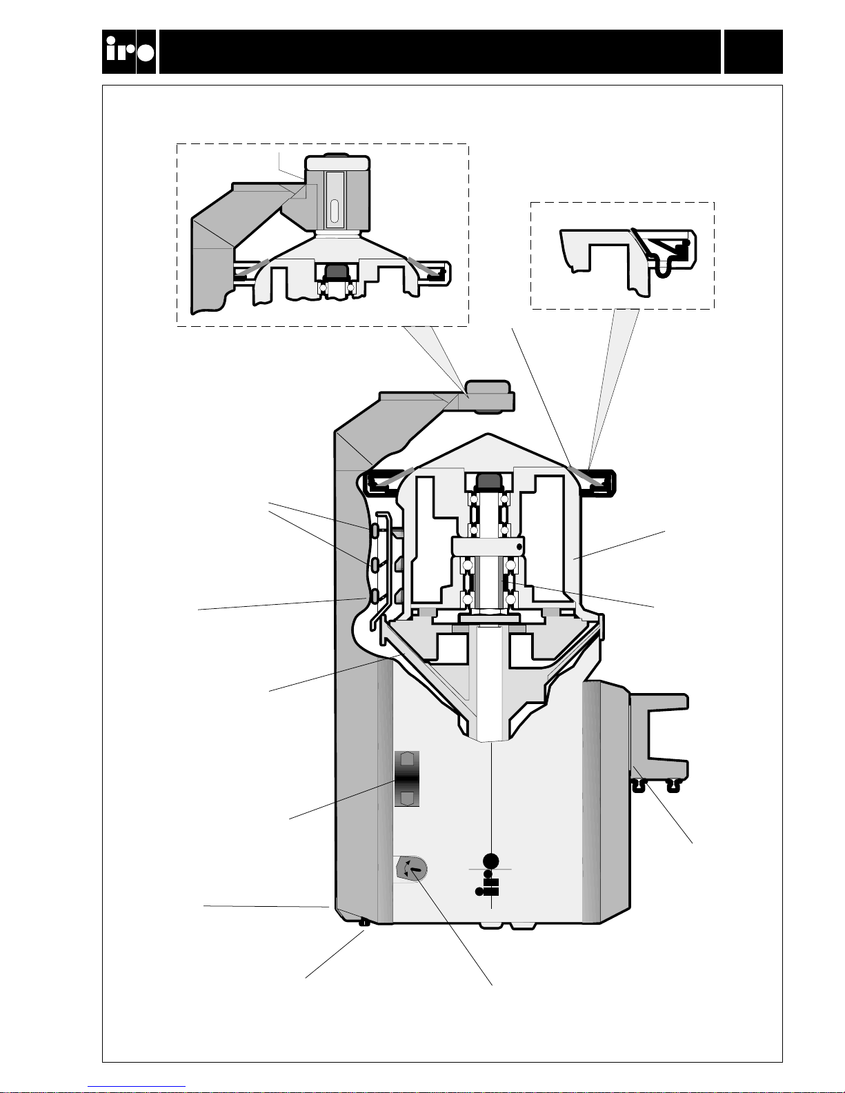
Main parts ........................................................................................................................................... 3
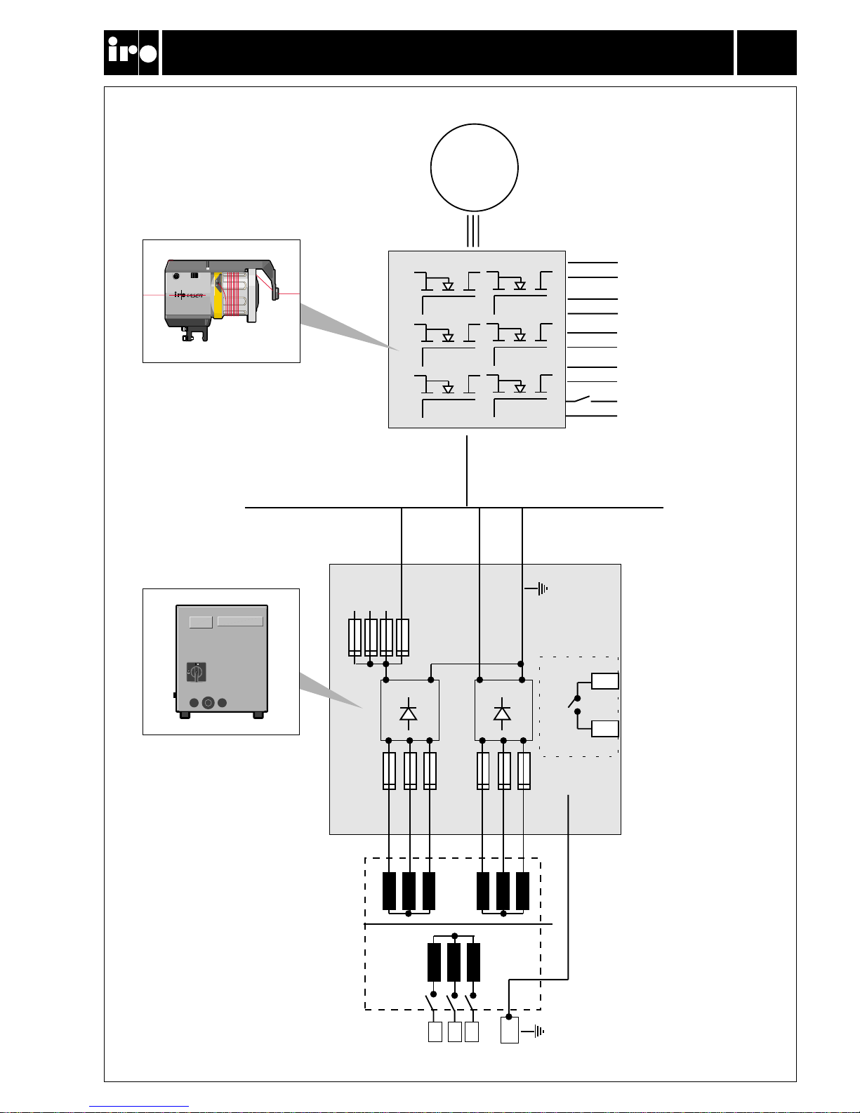
Operating diagram ........................................................................................................................ 4
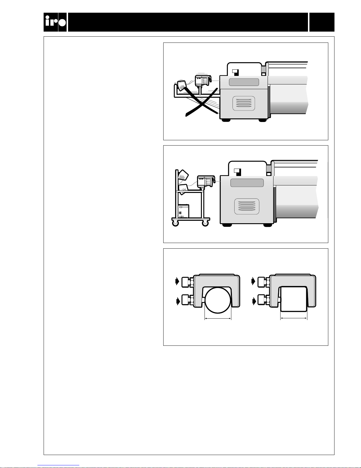
Installation ......................................................................................................................................... 5
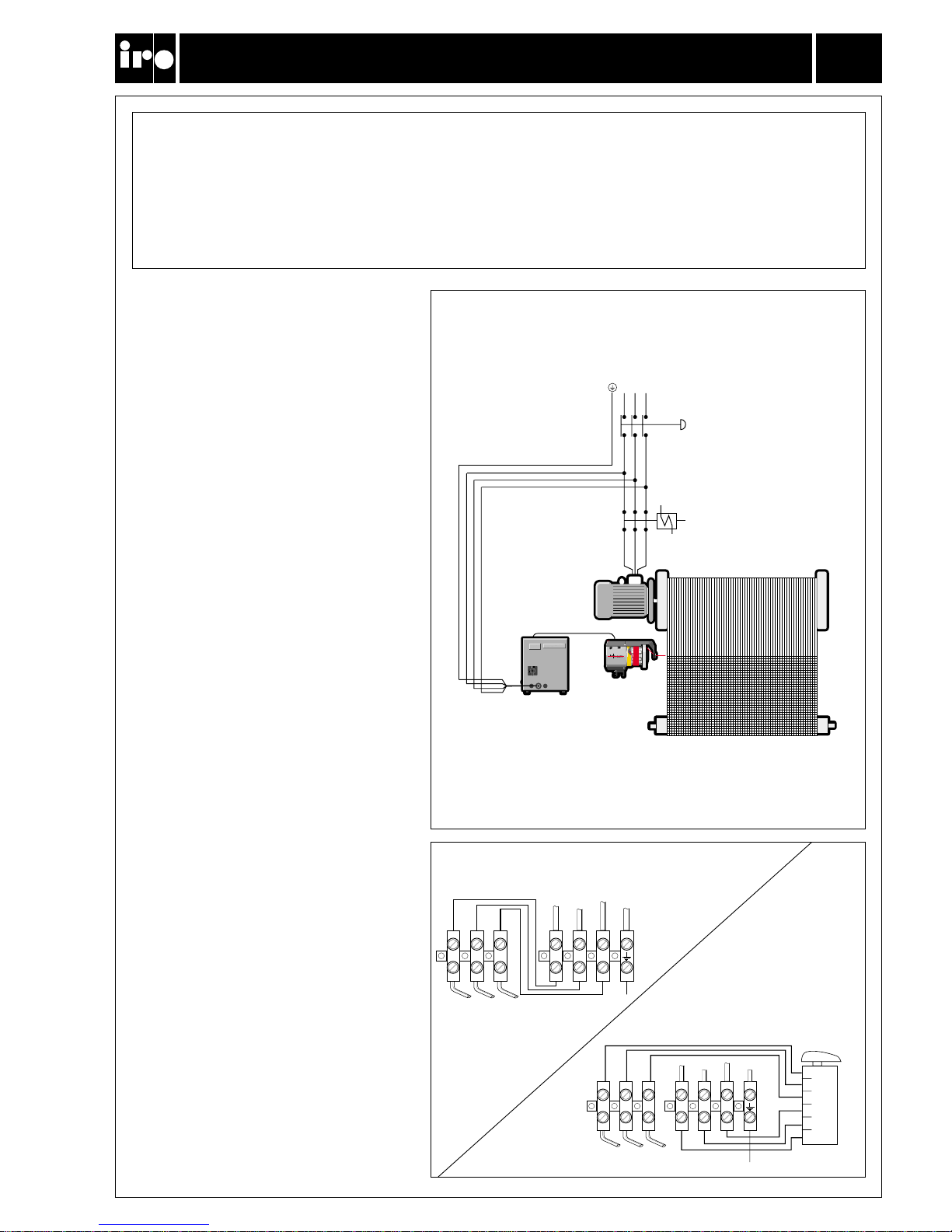
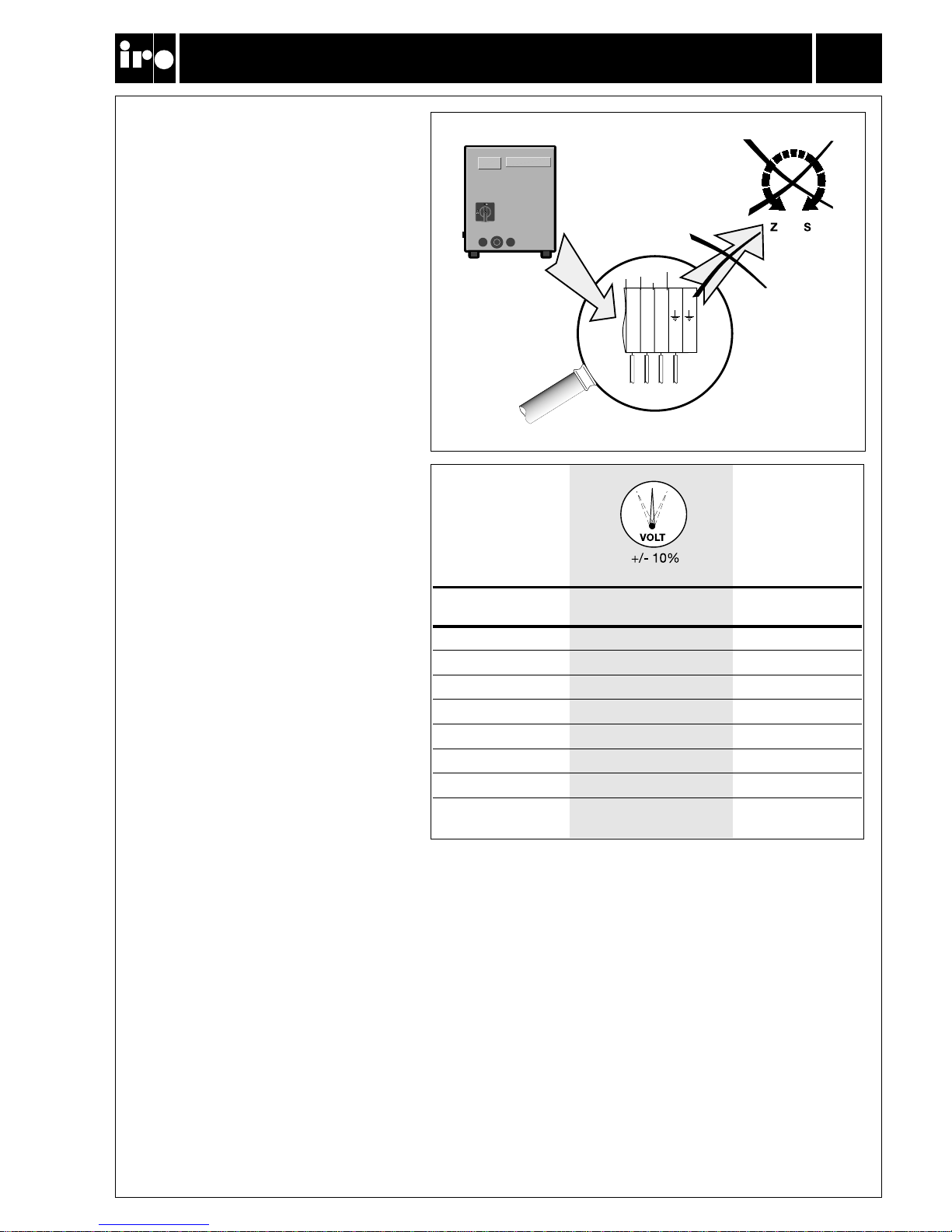
Mains connection .......................................................................................................................... 6
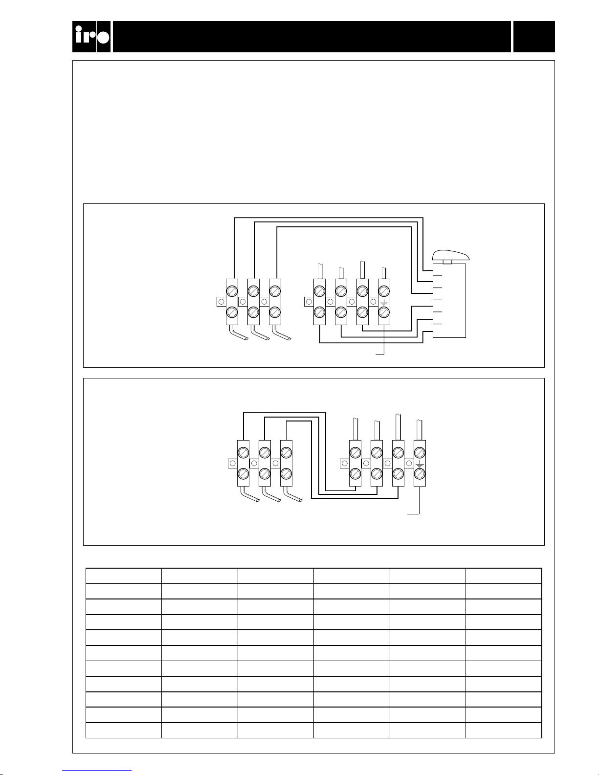
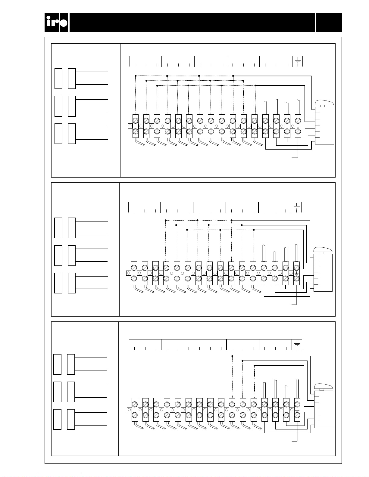
Wiring diagram ................................................................................................................................9
Motor circuit adjustments ........................................................................................................ 11
Yarn tension ...................................................................................................................................... 12
S/Z Adjustment ............................................................................................................................... 14
Threading ............................................................................................................................................ 15
Tension adjustment ...................................................................................................................... 16
Balloon adjustment ....................................................................................................................... 18
CAT adjustment .............................................................................................................................. 19
Maintenance ..................................................................................................................................... 20
Fault finding ...................................................................................................................................... 21
Technische Spezifikation .......................................................................................... 2
Hauptteile ................................................................................................................. 3
Funktionsdiagramm .................................................................................................. 4
Installation ................................................................................................................ 5
Hauptanschluss ........................................................................................................ 6
Schaltplan ................................................................................................................. 9
Motorschaltkreis-Einstellung .................................................................................... 11
Fadenspannung ........................................................................................................ 12
S/Z-Einstellung ......................................................................................................... 14
Einfädeln ................................................................................................................... 15
Fadenspannung-Einstellung ..................................................................................... 16
Ballon-Einstellung ..................................................................................................... 18
CAT-Einstellung ........................................................................................................ 19
Wartung .................................................................................................................... 20
Fehlersuche .............................................................................................................. 21