R
EFERENCE
I
NFORMATION
P
AGE
Assembly Prep & Intro 2
Parts Listing 3-5
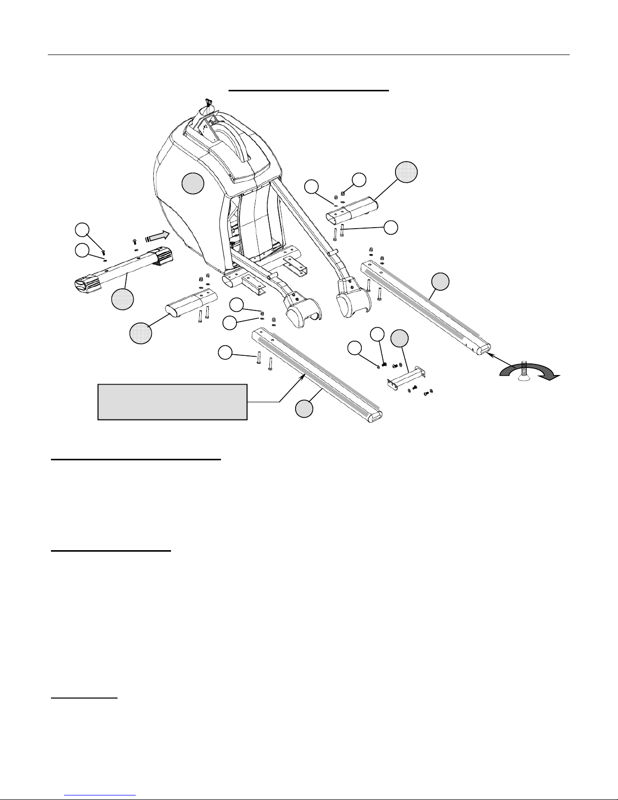
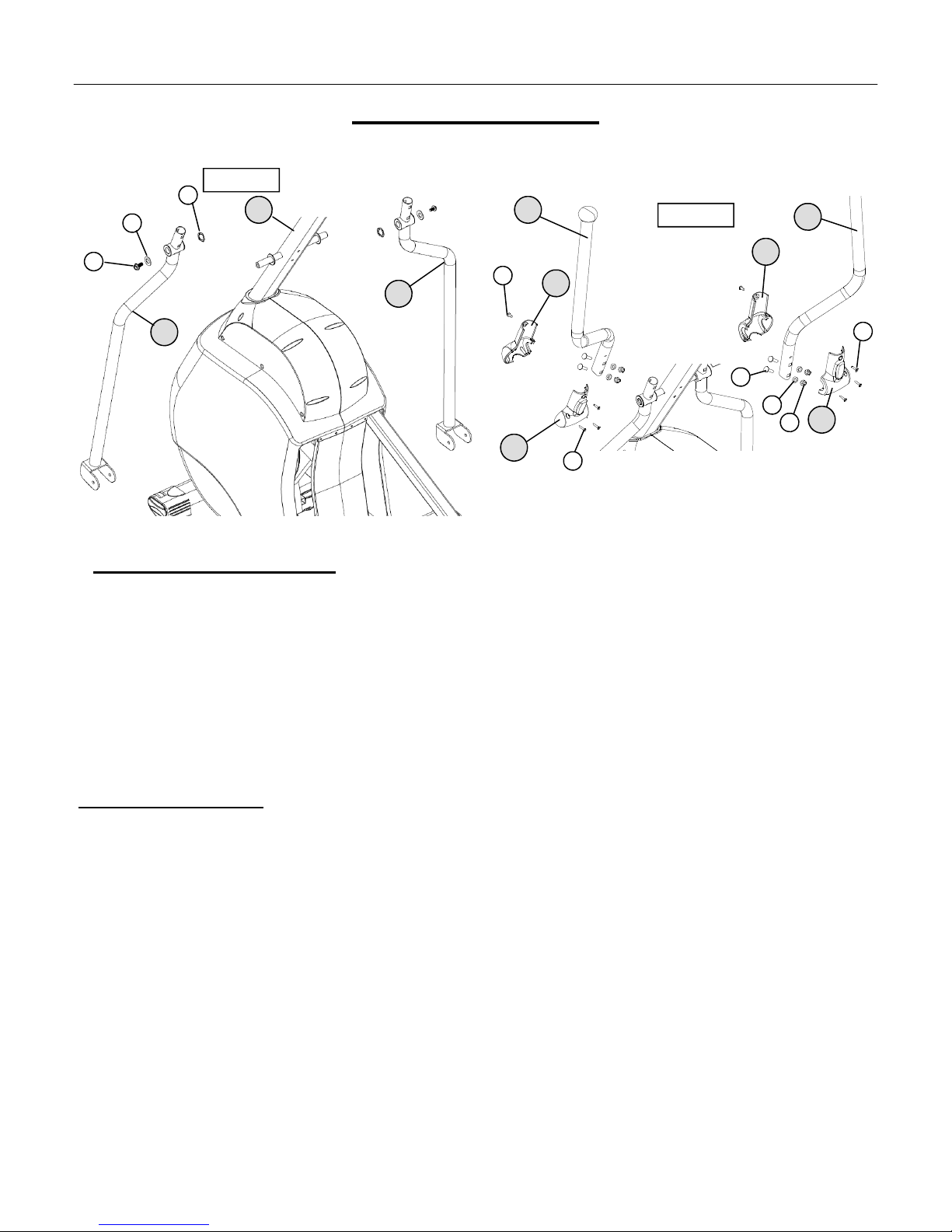
Product Exploded View 6
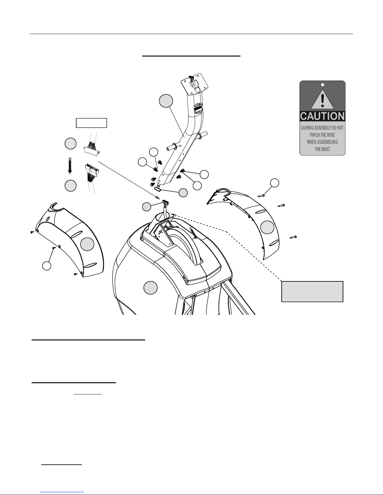
ProductAssembly Instruction 7-13
Computer Operation 14-16
Training Chart 17
Lubrication instruction (Important) 18
Troubleshooting 19
Preventative Maintenance 20
Warranty Terms 21
Product Registration 22
P
AGE
1 T
ABLE
OF
C
ONTENTS
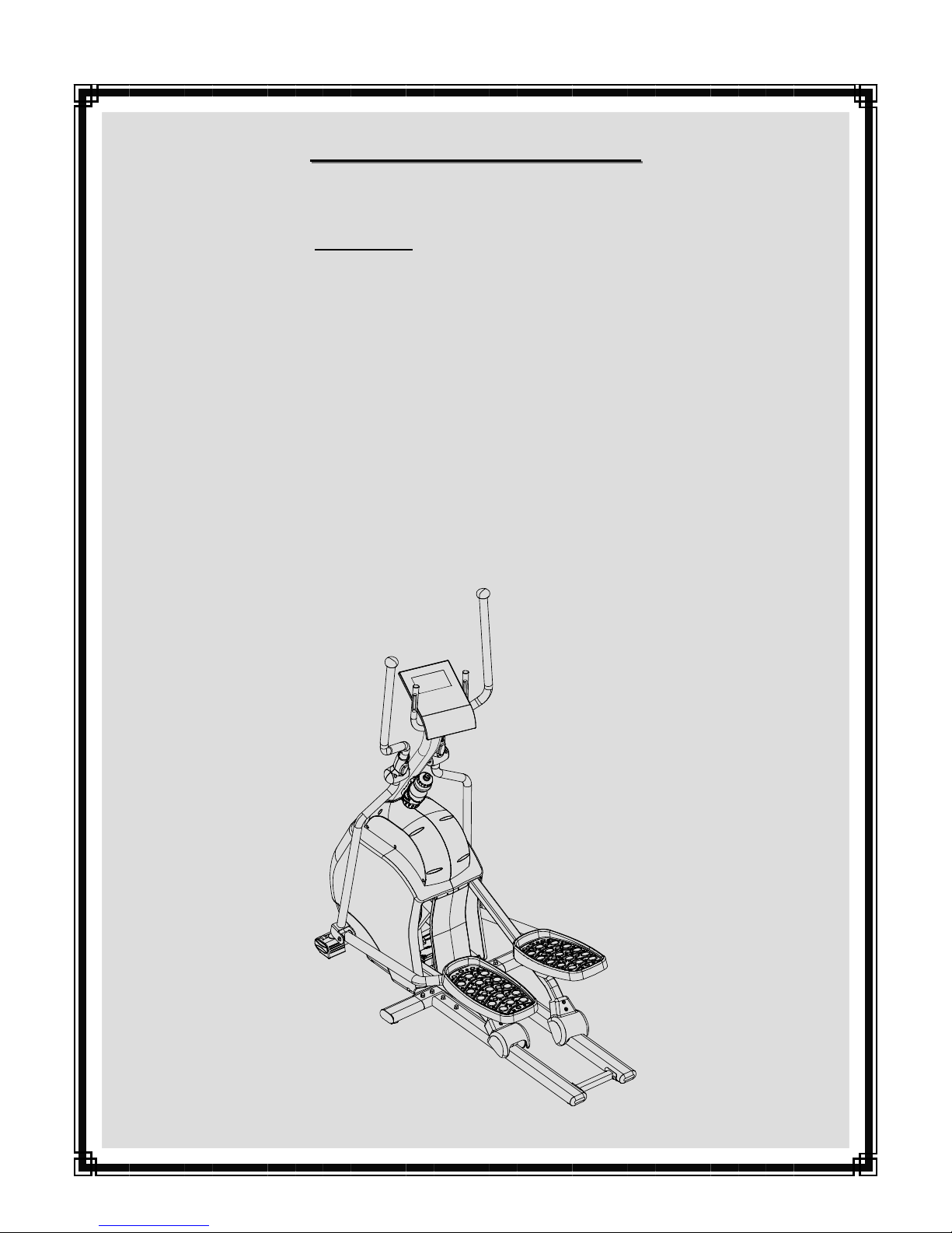
1840 E
1840 E
LLIPTICAL
LLIPTICAL
T
T
RAINER
RAINER
I
I
MPORTANT
MPORTANT
P
P
RECAUTION
RECAUTIONS
S
WARNING: To reduce the risk of injury, please read the following precautions before assembling or using your new product.
1. It is the responsibility of the owner to ensure that all users of this equipment are adequately informed of stated precautions.
2. Read all instructions and enclosed literature carefully. Understand the assembly and operation before using the equipment.
3. This equipment is intended for internal home use only. Do not use in a non-residential environment.
4. Use in non-recommended environments can lead to serious injury and will void all related warranties & liabilities.
5. Keep children & pets away from equipment at all times. Unplug equipment for added safety while not in use.
6. Use equipment on a flat level surface. Use the adjustment levelers on the bottom of equipment to help stabilize unit.
7. Allow proper space for use and set up of the equipment. Use care when mounting and dismounting equipment.
8. It’s recommended to place an exercise / product mat beneath the equipment for added protection of floors or carpets.
9. Inspect product on a frequent basis. Tighten loose assemblies or hardware as needed. Replace worn or damaged parts.
10. Wear proper workout apparel. Avoid wearing loose clothing or dangling shoe laces during use of equipment.
11. Frequently wipe equipment down with a dampened soft cloth.
12. Observe and adhere to all warning / caution labels posted on the equipment.
13. Properly warm-up and stretch before starting any strength training or cardio exercise routine.
14. If you feel pain or dizziness at any time while exercising, stop immediately and consult your physician .
15. Recommended user weight should not exceed 300 lbs.
Safety Warning: Before starting an exercise program, consult your physician. This is especially important for individuals over the age
of 35 or persons with pre-existing health problems. It’s important to read all instructions carefully. We assume no responsibility for
personal injury or consequential damages sustained by or through the use of this equipment. Additional terms & conditions are listed in
the back of this manual or enclosed owners manual.
StarTrac Health&Fitness,Inc.product aesthetics, packaging, operating functions, and warranty terms are subject to change without notice.