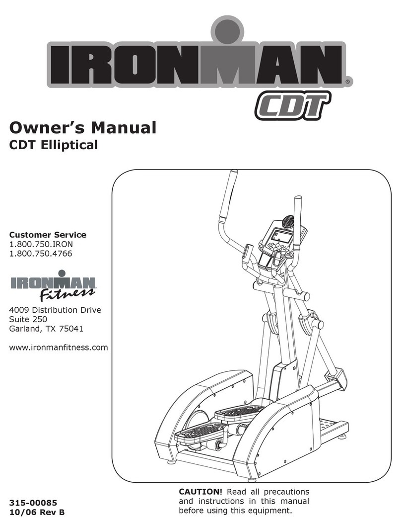
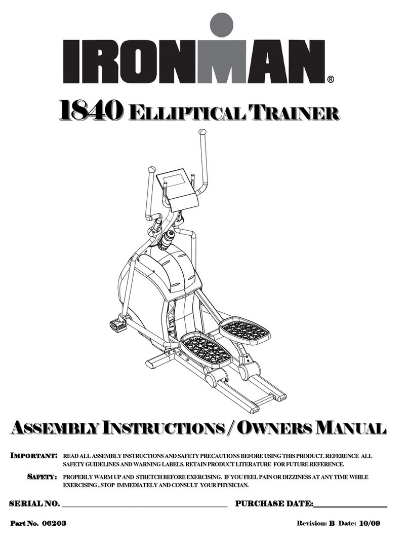
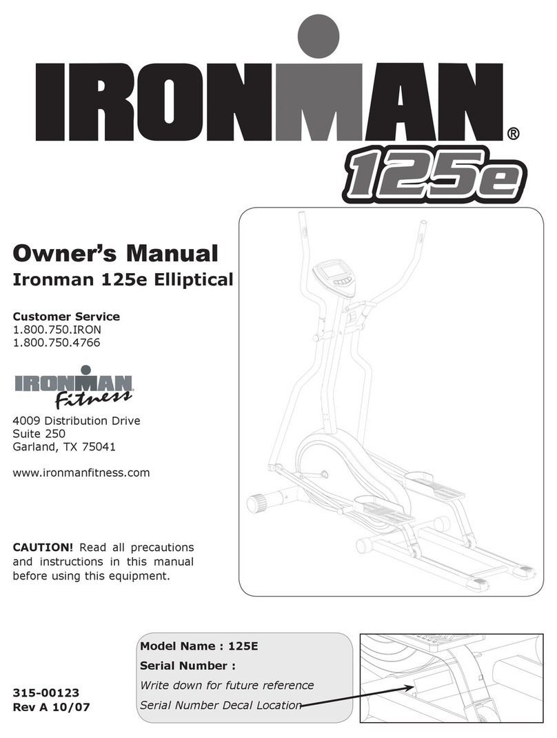
Ironman Fitness triathlon X-Class 610 User manual

The specifications of this product may vary from this photo and are subject to change without notice.
IRONMAN, IRONMAN TRIATHLON and M-DOT are registered trademarks of World Triathlon Corporation.
This product is licensed by the World Triathlon Corporation.
Model 6371
OWNER’S MANUAL
Triathlon X-Class 610
Smart Technology Elliptical Trainer with Bluetooth
1

6371.1-022615
2

SERVICE ------------------------------------------------------------------------ 4
LABEL PLACEMENT --------------------------------------------------------- 5
PRODUCT SAFETY ---------------------------------------------------------- 6
OVERVIEW DRAWING ------------------------------------------------------ 7
BOX CONTENTS ------------------------------------------------------------- 11
PARTS LIST -------------------------------------------------------------------- 9
ASSEMBLY --------------------------------------------------------------------- 13
COMPUTER -------------------------------------------------------------------- 23
13-------------------------------------------- ------------TLEBTSEHCETARTRAEH
TROUBLE SHOOTING & MAINTENANCE -------------------------- 32
WARM UP ----------------------------------------------------------------------- 33
WARRANTY -------------------------------------------------------------------- 34
FAX FORM ---------------------------------------------------------------------- 35
OF CONTENTSTABLE CONTENT
3

IMPORTANT: FOR NORTH AMERICA ONLY
To request product service and order
replacement parts, please call our
customer service department at:
1-844-641-7922
Monday through Friday, 8:00 AM-5:00 PM Pacific Standard Time,
or email us at: service@paradigmhw.com
Please visit our website at www.paradigmhw.com.
Please have the following information ready when requesting for service:
Your name
Phone number
Model number
Serial number
Part number
Proof of Purchase
Before returning this product to the store please contact
customer service at the contact number.
Paradigm Health & Wellness, Inc.
1189 Jellick Ave
City of Industry, CA 91748 USA
SERVICE
4

For customer assistance call:
1-844-641-7922
8 am - 5 pm PST
Mon - Fri
Pour le service a la clientèle
composer le:
1-844-641-7922
Du lundi au vendredi
8:00 h - 17 h (HNP)
SAFELY MOUNTING YOUR ELLIPTICAL MACHINE
1. Move the pedal on the side you intend
to mount to its lowest position.
2. Take hold of the handlebar nearest you
with the appropriate hand.
3. Place the appropriate foot onto the near
side pedal first, then the far pedal second.
4. Follow these steps in reverse order for dismounting.
1. Mettre en position la plus basse la pédale du côté ou l'on
monte ou descend
2. Agrippez la poignée la plus près de vous avec la main
appropriée
3. Mettre le pied sur la pédale du côté le plus proche en premier,
puis l'autre pied sur la seconde
4. Suivre ces mêmes instructions en sens inverse pour descendre.
Monter sur l'exerciseur elliptique et en descendre
8 0
8811506371
114228637100001
Serialnumber/ :Numéro de série
MADE IN TAIWAN/FABRIQUENTAIWAN
LABEL PLACEMENT
5

Basic precautions should always be followed, including the following safety
instructions when using this equipment. Read all instructions before using
this equipment.
1. Read all the instructions in this manual and do warm up exercises before
using this equipment.
2. Before exercising and to avoid injuring your muscles, perform warm-up
exercise for each muscle group is highly recommended. Please refer to
Warm Up section of the Owner’s Manual.
3. Please make sure all components are not damaged and in working order
before use. This equipment should be placed on a flat surface while in use.
Using a mat or other material on the ground is recommended.
4. Please wear proper clothes and shoes when using this equipment; do not
wear clothes that might catch in any part of the equipment.
5. Do not attempt any maintenance or adjustments other than those described
in this manual. Should any problems arise, discontinue use and consult
with customer service at Paradigm.
6. Caution should be taken when getting on or off the equipment. To get on,
make sure the left foot pedal is at the lowest position. Grab the stationary
handlebar firmly with both hands then place your left foot onto the left foot
pedal. Once your left foot is secured, place your right foot onto the right
foot pedal. To begin exercising, push/pull on the handrails first and then
follow with leg motion. To get off, come to a complete stop and do the
above in reverse.
7. Keep dry - do not operate in wet or moist condition.
8. Do not use the equipment outdoors.
9. This equipment is for household use only.
10. Only one person should be on the equipment at any time.
11. Keep children and pets away from the product while in use.
12. This machine is designed for adults only.
13. This product requires a minimum of 6 feet of space for safe operation.
14. If you feel any chest pains, nausea, dizziness, or shortness of breath, you
should stop exercising immediately and consult your physician before
continuing.
15. The maximum weight capacity for this product is 325 lbs /147 kgs.
WARNING: Before beginning any exercise program consult your
physician. This is especially important for the people who are over 35 years
old or who have pre-existing health problems. Read all instructions before
using any fitness equipment.
CAUTION: Read all instructions carefully before operating this
product. Retain this Owner’s Manual for future reference.
PRODUCT SAFETY
6

OVERVIEW DRAWING
B09
7

B09
OVERVIEW DRAWING
8

ytQ noitpircseDoNytQ noitpircseD oN
2 8M tloB91B 1 emarF niaM ,dedleW 10A
2 "8/3 tloB02B 1 tsoP thgirpU ,dedleW 20A
4 "8/3 rehsaW12B 1 tfeL/ mrA liardnaH ,dedleW 30A
2 "8/3 tuN emoD22B 1 thgiR/ mrA liardnaH ,dedleW 40A
8 6M wercS32B 1 tfeL/ ebuT ladeP tooF ,dedleW 50A
2 8M tloB42B 1 thgiR/ ebuT ladeP tooF ,dedleW 60A
1 8M tuN52B 1 tfeL/ ebuT etatoR ,dedleW 70A
3 01M tuN nolyN62B 1 thgiR/ ebuT etatoR ,dedleW 80A
A09 Welded, Front Stabilizer Tube 1 B27 C-ring ∅17 1
4 8M tloB egairraC82B 1 yelluP tfahS ,dedleW 01A
21 8M tuN nolyN92B 2 ylbmessA knarC ,dedleW 11A
21 8M rehsaW evruC03B 1 liaR ediuG epahS U ,ebuT 21A
13B 1
Handlebar /Left
31A Shaft∅20 2
6 8M tloB23B 1
Handlebar /Right
41A
6
"61/5 rehsaW33B 1 mrA leehW noisneT ,dedleW 51A
2 01M tloB43B 1 rabeldnaH yranoitatS 61A
4 8M tloB53B 2 tekcarB epahS U 71A
4 3M wercS63B 2 tekcarB tcennoC raB etatoR 81A
1 "61/3 wercS73B 2 ebuT ladeP tooF fo etalP ediS 91A
2 3M wercS83B 2 "4/1 tloB 10B
6 4M wercS93B 4 "4/1 rehsaW 20B
37
5M wercS04B 2 "4/1 tuN 30B
2 8M wercS14B 1 )T0.8( 01M tuN 40B
2 recapS gnihsuB24B 1 )T0.6( 01M tuN 50B
B06 C-ring ∅20 2 etalP cniZ34B 3
4 8M tloB44B 6 12M rehsaW evaW 70B
2
Phillip Round head Screw M5
54B 1 02M rehsaW 80B
B09 Screw 3/16" 4 8M tloB64B
2
74B 1 8M tloB 01B Plastic Washer ∅20 2
2 01M rehsaW gnirpS84B 1 01M tloB 11B
2 8M tloB94B 2 21M tloB 21B
05B 6 8M tloB 31B Tooth Lock Washer AW ∅84
4 recapS gnihsuB15B 6 "2/1 rehsaW 41B
4
"61/5 rehsaW25B 2 21M tuN 51B
1 R/ revoC niaM10C 2 8M tloB 61B
1 L/ revoC niaM20C 4 retupmoC rof swercS 71B
B18 Shaft ∅19 2 revoC csiD30C 2
PARTS LIST
9

ytQ noitpircseD oNytQ noitpircseD oN
62C 4 paC dnE 40C Washer ∅14 4
1 redloH elttoB72C 4 A- daP tooF 50C
4 paC dnE82C 2 leehW 60C
C07 Post Cover Left Washer ∅20.5 2
2 paC dnE03C 1Post Cover Right 80C
teS1 rosneS esluP dnaH10D 4 paC dnE 90C
1 retupmoC20D 1 tleB 01C
1 leehwylF citengaM30D 6
Nut Cap M8
11C
1 elbaC reppU40D 2 ladeP tooF 21C
1 elbaC rewoL50D 2 pirG maoF 31C
60D 2 daP noihsuC 41C Motor1
1 elbaC rosneS70D 2 pirG maoF 51C
1 rotpadA CA80D 2 paC dnE 61C
1 elbaC gulP CA90D 2dlebar Cover AnaH 71C
teS1 elbaC esluP dnaH01D 2dlebar Cover BnaH 81C
1 elbaC noisneT rotoM11D 1 yelluP 91C
41 4006 gniraeB10E 2 relloR 02C
4 3006 gniraeB20E 2 B- daP tooF 12C
C22 Washer ∅17 4 1006 gniraeB30E 4
2 3026 gniraeB40E 2 recapS tsoP thgirpU 32C
2 4015 gniraeB50E 2 revoC knarC 42C
2 liaR munimulA10F 4 4.33Ø gnihsuB 52C
PARTS LIST
1 C29
10

BOX CONTENT
11
(A13/A14)
Handlebar L/R
2 PCS
(A03/A04) Handrail
Arm L/R
2 SETS
(C11) Nut Cap M8
4 PCS
(A06/08) Foot Pedal Tube/R
Rotate Tube/R
1 SET
BOX B
(C14) Cushion Pad
2 PCS
(A05/A07) Foot Pedal Tube/L
Rotate Tube/L
1 SET
(C12) Foot Pedal
2 PCS
(A12) U Shape Guide Rail
1 SET Lubricant
1 PCS
(A01) Main Frame
1 SET
(A16) Stationary Handlebar
1 SET (D02) Computer
1 PCS
(A09) Front Stabilizer
1 SET (A02) Upright Post
1 SET
(C07/C08) Upright
Post Decorative Cover
1 SET
(C17/C18) Handrail Arm
Decorative Cover-A/B
2 SET
(D08)Adapter
1 PCS
(C27) Water Bottle
Holder
1 PCS
BOX A

BO
X
X
B
C
(B44) Bolt M8x20mm
4PC
(B33)W
C
ON
T
Washer 5/16”
4PC
T
AIN
S
(B30)Cu
M8x
”x30x2.0T
S
HA
R
urve Washer
x20x1.5T
(B41)Screw
2P
(B2
R
DW
A
w M8x25mm
PC
28)Bolt M8x5
4PC
A
RE
B
(B32)H
50mm (
& T
O
B
4PC
Hexagon Hea
M8x16mm
4PC
(B40)Screw
10P
O
OLS
ad Bolt
M5x16mm
PC
BOX CONTENT
12
(B29) Nylon Nut M8x7.7T
4PC
(T03) Allen Wrench (M5)
1PC
(T02) Allen Wrench (M6)
1PC
(T01) Hex Tool Phillips Screwdriver
(13mm/14mm)
1PC

2. Front Stabilizer Installation
Attach the Front Stabilizer (A09) onto the curve plate of the Main Frame (A01)
and align the bolt holes with 2 Bolts (B20), 4 Washers (B21)and 2 Dome Nuts
(B22).Tighten bolts with the Hex Tool (T01) provided.
Hardware:
(B20) Bolt 3/8”x64mm 2PC
(B21)Washer3/8”x20x2.0T 4 PCS
(B22)Dome Nut 3/8”X17T 2PC
1. Remove Front Protection Bar
Place a Styrofoam Block under the Main Frame (A01) for easier removal of the Front Protection
Bar.This bar may be discarded.
Loosen the Dome Nuts (B22) first and then the Bolts (B20) and Washers (B21) with the Hex Tool
(T01) provided. Keep these for the next step. Remove the front protection bar from the Main Frame.
Tool:
Tool:
(T01)Hex Tool with Phillips Screwdriver
(13mm/14mm)
ASSEMBLY
Styrofoam block
13
(T01)Hex Tool with Phillips Screwdriver
(13mm/14mm)

(B44) Bolt M8x20mm
4PC
4. Upright Post Installation
This assembly step requires 2 people.
Lift up the Upright Post (A02) and connect the wires (D04/D05),then gently tuck the
excess wire into the Upright Post (A02) and Main Frame (A01).
Assemble the Upright Post (A02) with 4 Bolts (B44) and hand tighten them to ensure proper
hole alignment. After all 4 bolts are in, secure them with the Hex Tool (T01) Provided.
(T01)Hex Tool with Phillips Screwdriver
Remove 6 Curve Washers M8 (B30) and 6 Bolts M8 (B13) from the Main Frame (A01) and
use them to install the U Shape Guide Rail (A12) onto the 3 tubes of the Main Frame.
3. U Shape Guide Rail Installation
(T03)Allen Wrench (M5) 1 PCS
ASSEMBLY
IMPORTANT: After A12 is installed,
tighten Bolts (B49) on the Aluminum Rail (F01).
14

6.Handrail Arm Installation
Insert the Right Handrail Arm (A04) all the way onto the horizontal axle of Upright Post
(A02) and secure the Right Handrail Arm (A04) in position with 1 Hexagon Head Bolt
M8 (B32) and 1 Washer 5/16” (B33).
Repeat for the left side
5. Lubricating the Horizontal Axle and Crank Axle
Apply some lubricant onto both horizontal axles of the Upright Post (A02)
and both axles of the Crank (A11).
Remark: Gently apply lubricant evenly on Upright Post (A02). Brush tool is recommended.
Lubricant
ASSEMBLY
15
(T01) Hex Tool with Phillips Screwdriver
(B33) Washer 5/16'' x30x2.0T
(B32) Hexagon Head Bolt

(B33) Washer 5/16”x30x2.0T
2PC
(B32) Hexagon Head Bolt M8
2PCS
(T01)Hex Tool with Phillips Screwdriver
7. Pedal Installation
ASSEMBLY
Attach the Cushion Pad onto the Foot Pedal.
Repeat this step for the left side
8. Tube Assembly
Place the Right Rotate Tube (A08) onto the Aluminum Rail (F01). Insert the Right Rotate
Tube onto the axle of Crank (A11) and secure the Bolt (B32) and Washer (B33) using the
Hex Tool (T01). Attach Nut Cap (C11).
Repeat this step for the left side
16
Remove the 4 Screws (B23) from the Right Foot Pedal Tube (A06).
Install Foot Pedal (C12) with the removed screws.

B52
Important: Remove twist ties and ensure that
Washers (C22) are in place before assembly!
(T02)Allen Wrench (M6)
ASSEMBLY
9. Handrail Arm Assembly
Remove Bolt (B24), Washer (B52) and Nut (B29) from the Right Handrail Arm (A04)
Put the Right Handrail Arm onto the Right Foot Pedal Tube (A06). Install with the
previously removed hardware by inserting the Allen Wrench into the Bolt (B24) and
tightening the Nut (B29) with the Tools (T01/T02). Attach the Nut Cap (C11).
Repeat this step for the left side.
17
(T01)Hex Tool with Phillips Screwdriver
C22

B28
(B28)Carriage Bolt M8
2 PCS
2 PCS
(B29)
N
N
ylon Nut
M
M
8x7.7T
(B30)C
u
M8x2
0
u
rve Was
h
0
x1.5T 2PC
h
e
r
(B41) Screw M8x25mm
2PC
(T03)Allen Wrench (M5)
(T01)Hex Tool with Phillips Screwdriver
ASSEMBLY
10. Stationary Handlebar Installation
Carefully, route both cables from Upright Post (A02) through the square hole of Stationary
Handlebar (A16). Ensure the cables are not pinched or damaged during installation.
Attach the Stationary Handlebar on the Upright Post with 2 Screws (B41) and tighten.
11. Handlebar Installation
Insert Handlebar Right (A14) into Handrail Arm (A04)
Tighten with 2 Bolts (B28), 2 Curve Washers (B30) and 2 Nylon Nuts (B29)
Repeat this step for the left side.
Cable
18

(T01)Hex Tool with Phillips Screwdriver
ASSEMBLY
12. Computer Installation
Remove 4 Screws (B17) from the back of the Computer (D02)
Connect both wires from the Stationary Handlebar (A16) to the Computer. Use the 9 pin white
socket port. Gently tuck the cables into the Stationary Handlebar and ensure the wires are not
pinched.
Secure the computer to the Stationary Handlebar using the previously removed 4 screws.
19

(B40) Screw M5x16mm
2PCS
(T01)Hex Tool with Phillips Screwdriver
(B40) Screw M5x16mm
4PCS
ASSEMBLY
13. Post Cover Installation
Attach the Post Cover (C07, C08) onto Upright Post (A02) with 2 Screws (B40)
14. Handlebar Cover Installation
Attach Handlebar Covers (C17, C18) onto the Right Handrail Arm (A04) with 4 Screws (B40)
Repeat this step for the left side.
20
(T01)Hex Tool with Phillips Screwdriver
Table of contents
Other Ironman Fitness Elliptical Trainer manuals

Ironman Fitness
Ironman Fitness ASCENDER User manual

Ironman Fitness
Ironman Fitness M3EL User manual

Ironman Fitness
Ironman Fitness Aeros User manual

Ironman Fitness
Ironman Fitness 1840 Quick start guide

Ironman Fitness
Ironman Fitness 1880 Quick start guide

Ironman Fitness
Ironman Fitness ATIS 4000 User manual

Ironman Fitness
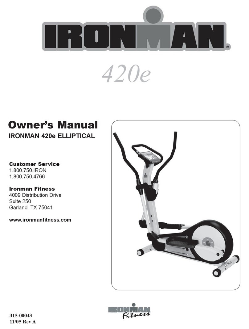
Ironman Fitness 420E User manual

Ironman Fitness
Ironman Fitness 130e User manual

Ironman Fitness
Ironman Fitness IRONMAN 120e User manual

Ironman Fitness
Ironman Fitness H-Class 610 User manual