Ironman4x4 BBT034 User manual

BBT034/ BBC034/ BBCD034
BBCD060/ BBT060-NL/
BB060-TL/ BB060-SL
VOLKSWAGEN AMAROK
INSTALLATION
GUIDE
• Ironman 4x4 BBT/ BBC/ BBCD034 BBCD060/ BBT060-NL/
BB060-TL/ BB060-SL Bull Bars fit to a Volkswagen Amarok.
• It will take about 3 hours to install.
IMPORTANT - If your vehicle has front parking sensors and you
wish to refit them, refer to drilling diagram on back pages of
instruction manual.
IMPORTANT: Bull Bar installations should only be done by a qualified
person and it is the responsibility of this person to ensure correct fitment.
NOTE: This product has been tested for air bag compatibility
and therefore the mounting system MUST NOT be modified
080518

Page 2 of 17
1. Before installation check bull bar application
is compatible with your vehicle.
2. Remove bumper bar, grill, bumper bar
reinforcement and horns.
3. Remove flares from ends of bumper bar.
4 Mask a straight line level with the top of the
lower grill opening in the bumper, across the top
of the fog light housing to the ends of the bumper
as shown.
5. Using an air hack saw or similar, cut along the
line previously marked to remove the lower
section of the bumper.
6. Mask a line down the bumper ends where the
edges of the flares contact the bumper.

Page 3 of 17
7. Place bumper cutting templates onto the ends of
the bumper, mark and remove sections as shown.
Note: Cutting templates can be found of the last
pages of the fitting manual.
8. Remove ambient air temperature sensor and fit to
plastic panel as shown.
9. Place chassis bracket in position on chassis and
mark location of all mounting holes onto front
cross member. Remove chassis bracket and drill
all holes to 12.5mm.
7 x Holes will need to be drilled to 12.5mm in front cross member
10. Refit chassis bracket and secure in place using
M12 hardware provided.

Page 4 of 17
12. Refit horns as shown.
13. Refit plastic bumper reinforcement and top
section of bumper bar.
11. Using outer mounting holes of chassis bracket
as a guide, drill four outer holes in front cross-
member and fit inner and outer reinforcing
brackets to chassis as shown.
NOTE: Nut, flat washer and
spring washer between
bracket and crossmember.
INNER
OUTER
14. Using flare cutting templates, mark and cut flares
previously removed from the bumper bar.

Page 5 of 17
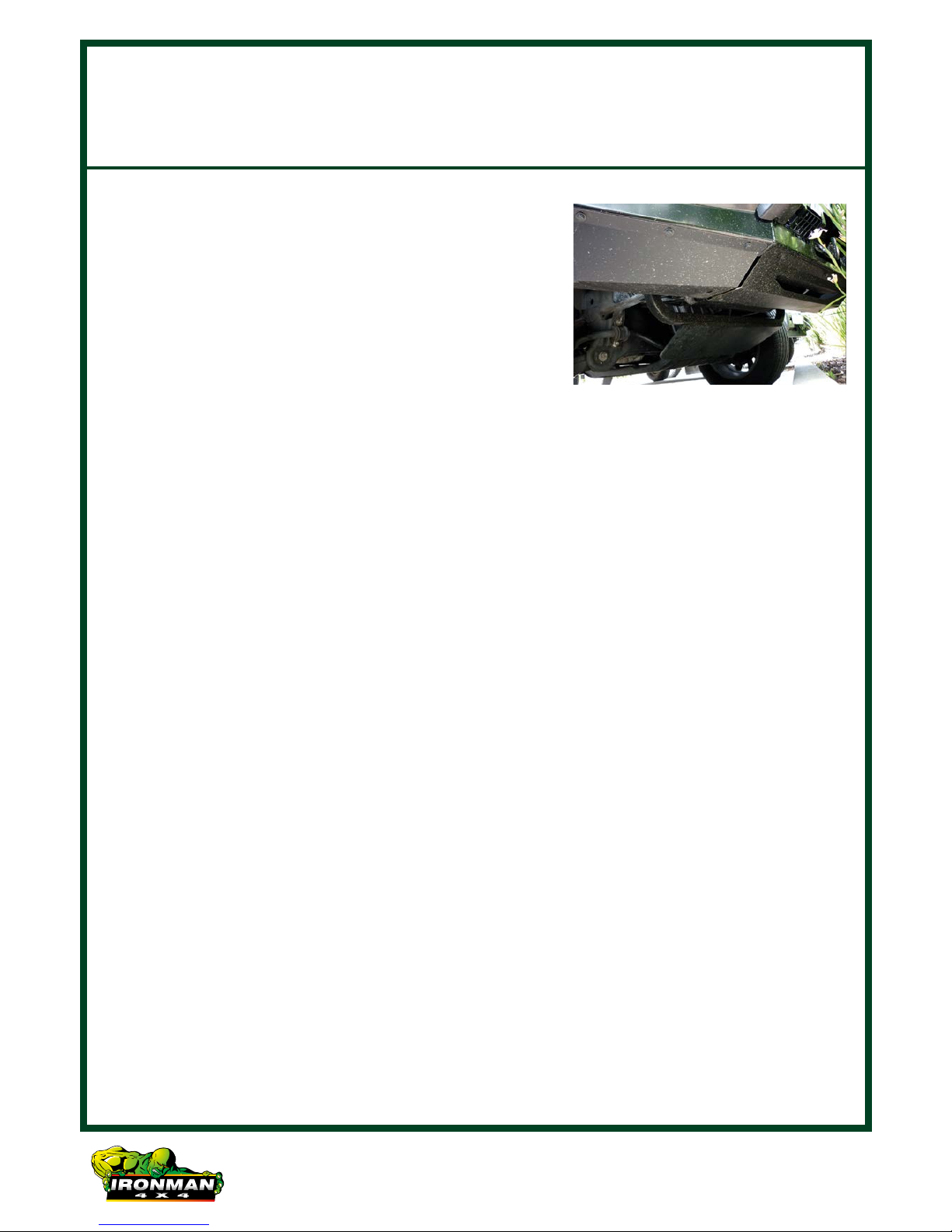
16. Trim mud guard liners as shown.
17. If winch is being installed, refer to winch
installation instructions pages 7-9.
18. Unwrap bull bar. Check over riders and light
assemblies are tight in bull bar before installation.
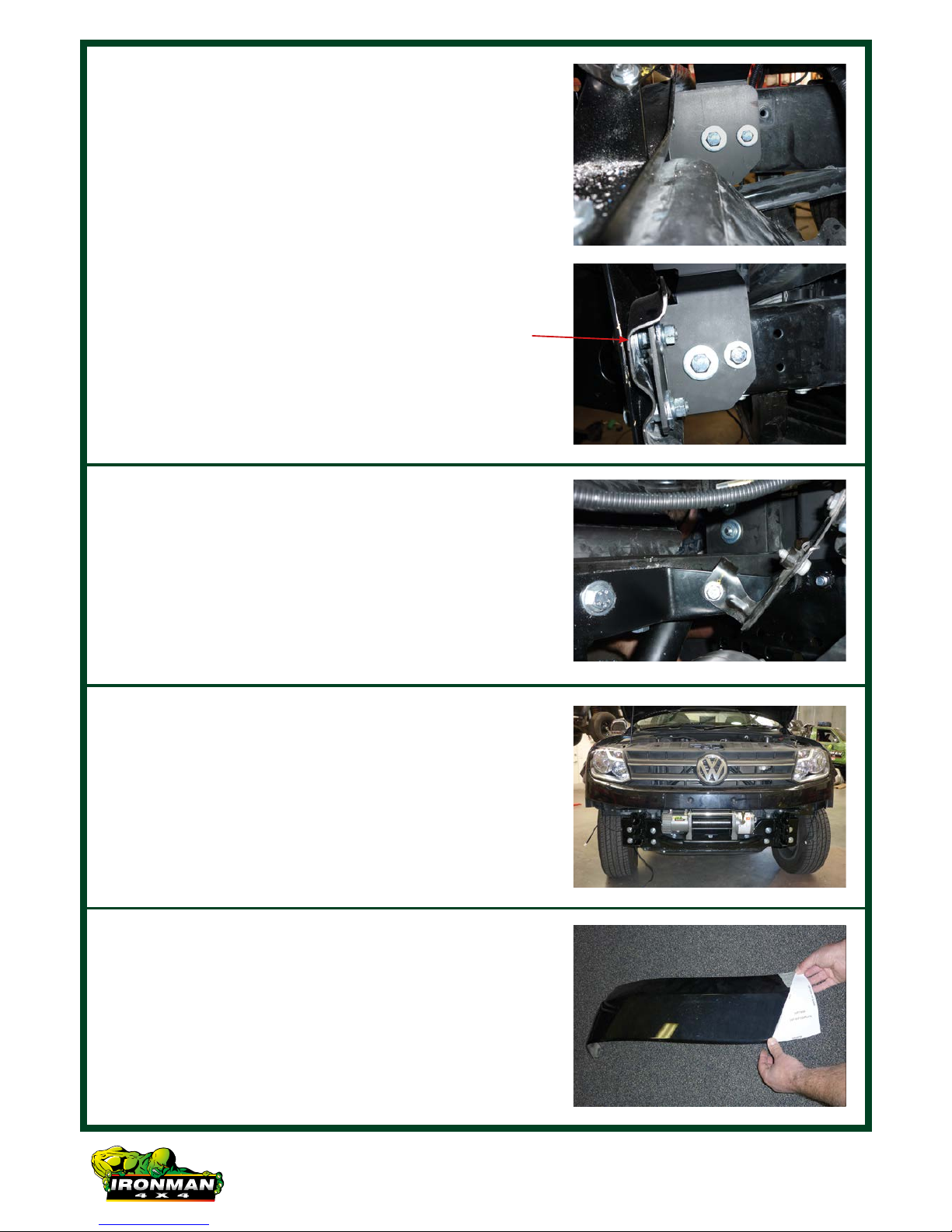
19. Fit bull bar to chassis bracket using M12
hardware provided. Align bar with vehicle and
tighten all bolts.
15. Refit small sections of flare removed in previous
step (Using factory screws and double sided tape
provided) along the edge of flare that contacts
the bumper.
Double sided tape
along this edge
20. Once bar is aligned with vehicle and tightened,
drill through pinning holes between bull bar and
chassis bracket and secure with bolts, washers
and nuts provided.

Page 6 of 17
22. Fit protection plates to underneath of bull bar
using M8 bolts, spring washers and flat washers
into bull bar.
21. Connect park lights, indicators and fog lights
as per wiring diagrams at the back of instruction
manual.

Page 7 of 17
Winch Installation
1. Bolt winch to cradle with gearbox to the left hand
side of vehicle and cable spooling from bottom of
the cable drum using bolts and washers provided.
2. Bolt fairlead to recess in front of bull bar using
bolts, washers and nuts provided.
3. Fit bull bar to vehicle referring to steps of bull bar
fitting instructions.
4. Mount control box in desired location.
5. Connect three colour coded cables to the
corresponding poles on winch motor.

Page 8 of 17
8. Connect positive and negative battery cables
main battery of vehicle (Not Auxilliary Battery).
9. Attach breather hose to barb fitting on winch
motor. Run hose to the highest available point
in engine bay and cable tie in position. Cable tie
hose away from any sharp, hot or moving objects.
7. Run the positive and negative battery cables into
the engine bay taking care to secure cables away
from any sharp or moving objects.
6. Connect the thin black earth wire and negative
battery cable to the earth connection on the
opposite side of winch motor.

Page 9 of 17
Wiring Diagrams
Parklight
Blue
Relay
Connector
Ground
Fuse
Red
3085
86
87
87a
Red Lamp
Black
LampBattery
Ground
Ground
White
Switch
SPST
Park Light Indicator
Ground Ground
Indicator
Circuit
Park Light
Circuit Black
YellowWhite
Black
PARK LIGHT & INDICATOR
FOG LIGHTS

Drawn October 2011
PREVIOUS CUT
CUT
NON-FLARED MODEL ONLY
FLARED MODEL ONLY
CUT
NON-FLARED MODEL ONLY
CUT
FLARED MODEL ONLY
RIGHT SIDE
TOP CUT
PREVIOUS CUT
TOP CUT
LEFT SIDE
+61 3 9532 1111
1300 731 137
www.ironman4x4.com
CUT OUT TEMPLATE
CUT
CUT OUT TEMPLATE
WHEEL ARCH
WHEEL ARCH
VOLKSWAGEN AMAROK
IRONMAN 4X4 BULLBAR
BUMPER CUTTING TEMPLATE

BUMPER
TOP EDGE OF FLARE
CUT
BUMPER
RIGHT SIDE
CUT
VOLKSWAGEN AMAROK
IRONMAN 4X4 BULLBAR
FLARE CUTTING TEMPLATE
CUT OUT TEMPLATE CUT OUT TEMPLATE
LEFT SIDE
+61 3 9532 1111
1300 731 137
www.ironman4x4.com
Drawn October 2011
TOP EDGE OF FLARE

Page 1 of 5
1. For new vehicles with parking
sensors, the new bars will now
come with a plastic parking sensor
holder kit. The sensor mounting
kit will be inside the bar mounting
hardware box.
IMPORTANT: Parking sensors should be installed as close to the same
direction as when they sit in the factory bumper.
2. The bars come with a rubber plug
in the sensors hole. This plug
needs to be pushed out if you
need to install the sensors into
the bar.
Plastic Parking Sensor Installation
Page 12 of 17

Page 2 of 5
3. Using some cleaner, clean around
the sensor hole on the INSIDE of
the bar.
4. The kit comes with double sided
stickers to enable you to stick the
sensor holder in place.
5. Remove the middle of the sensor
holder to allow the vehicle sensor
to go through.
Page 13 of 17

Page 3 of 5
6. Clean the plastic sensor holder
and install the double sided
sticker.
7. Remove the double sided stickers
protective layer and install the
sensor holder into the bar.
IMPORTANT: Parking sensors
should be installed as close to the
same direction as when they sit in
the factory bumper.
Page 14 of 17

Page 4 of 5
8. Remove the parking sensor from
the factory bumper and ensure the
rubber liner is in place.
9. The parking sensor kit allows the
backing plate to go 2 ways.
Depending on the thickness of the
sensor, you can adjust fitment.
If the sensor is larger, install the
sensor backing plate with the
smooth side down. If the sensor
is smaller, install the packing plate
with the spacer side down.
Page 15 of 17

Page 5 of 5
10. Install the backing plate to suit the
sensor.
11. Ensure that the sensor is installed
correctly and centred.
Page 16 of 17

Page 17 of 17
This manual suits for next models
6
Table of contents