evertz 7700 Series User manual

7700 MultiFrame Manual
7700PTX-PB Pro-Bel Protocol Translator
Revision 1.4
TABLE OF CONTENTS
1. OVERVIEW..................................................................................................................................... 1
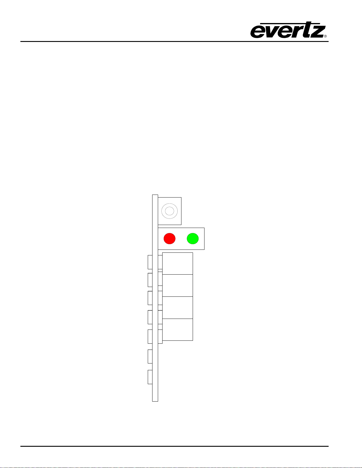
2. CARD EDGE CONTROLS..............................................................................................................2
2.1. DETERMINING CURRENT IP ADDRESS SETTINGS.......................................................... 2
2.2. RESTORING FACTORY DEFAULTS.................................................................................... 2
2.3. CARD EDGE LEDS ............................................................................................................... 2
3. TECHNICAL SPECIFICATIONS..................................................................................................... 3
3.1. DATA INPUT SERIAL PORT................................................................................................. 3
3.2. ELECTRICAL......................................................................................................................... 3
3.3. PHYSICAL ............................................................................................................................. 3
4. CONFIGURATION.......................................................................................................................... 4
4.1. CONFIGURATION STEPS .................................................................................................... 4
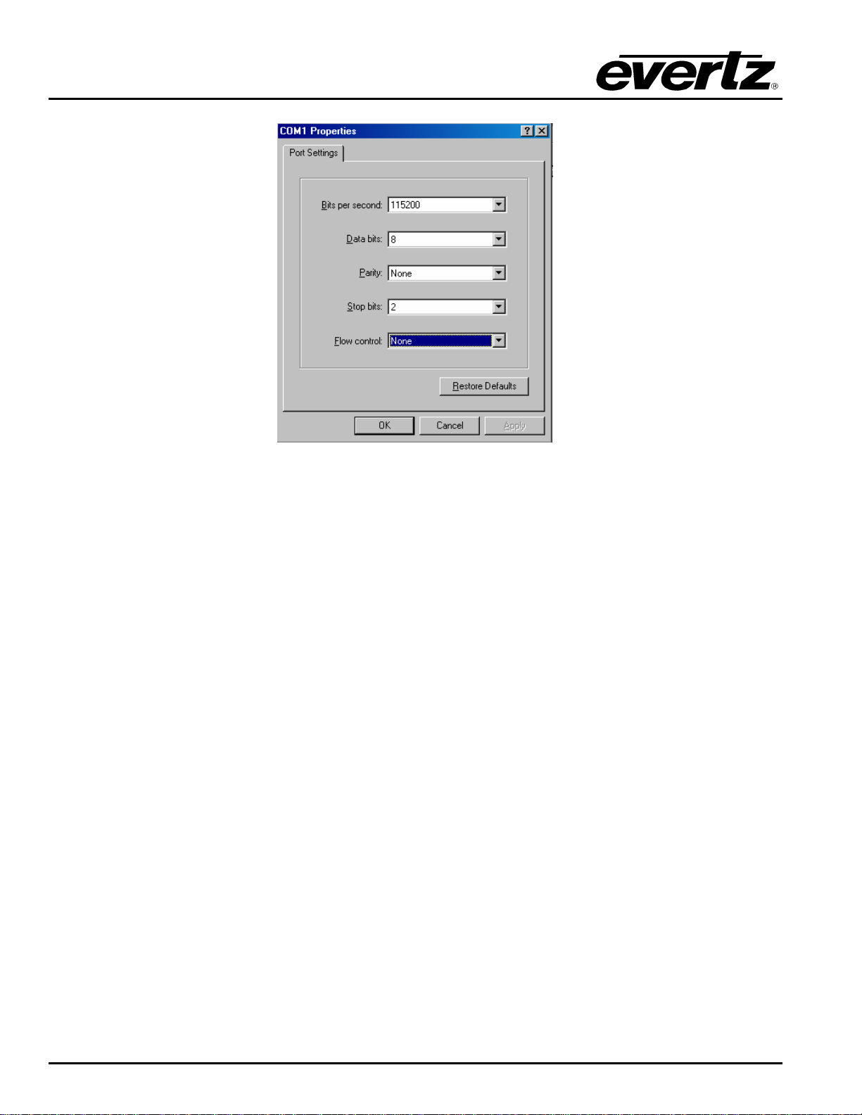
4.2. DEBUG/MONITOR PORT CONNECTION............................................................................. 4
4.3. MAIN MENU........................................................................................................................... 7
4.4. NETWORK CONFIGURATION.............................................................................................. 8
4.5. SERIAL PORT SETUP .......................................................................................................... 8
4.5.1. Parameters .................................................................................................................8
4.5.2. Back Plate...................................................................................................................9
4.5.3. RS-232 Wiring........................................................................................................... 10
4.5.4. RS-422 Wiring........................................................................................................... 11
4.6. PRO-BEL PROTOCOL SETUP........................................................................................... 12
4.6.1. Refresh Cycle Count.................................................................................................12
4.6.2. Display ID Offset.......................................................................................................12
4.6.3. UMD Text Selection..................................................................................................13
4.7. UNDER MONITOR DISPLAY SETUP ................................................................................. 13
5. TROUBLESHOOTING TIPS......................................................................................................... 14
5.1. CHECKING PRO-BEL COMMUNICATION......................................................................... 14
5.2. CHECKING UMD COMMUNICATION................................................................................. 15
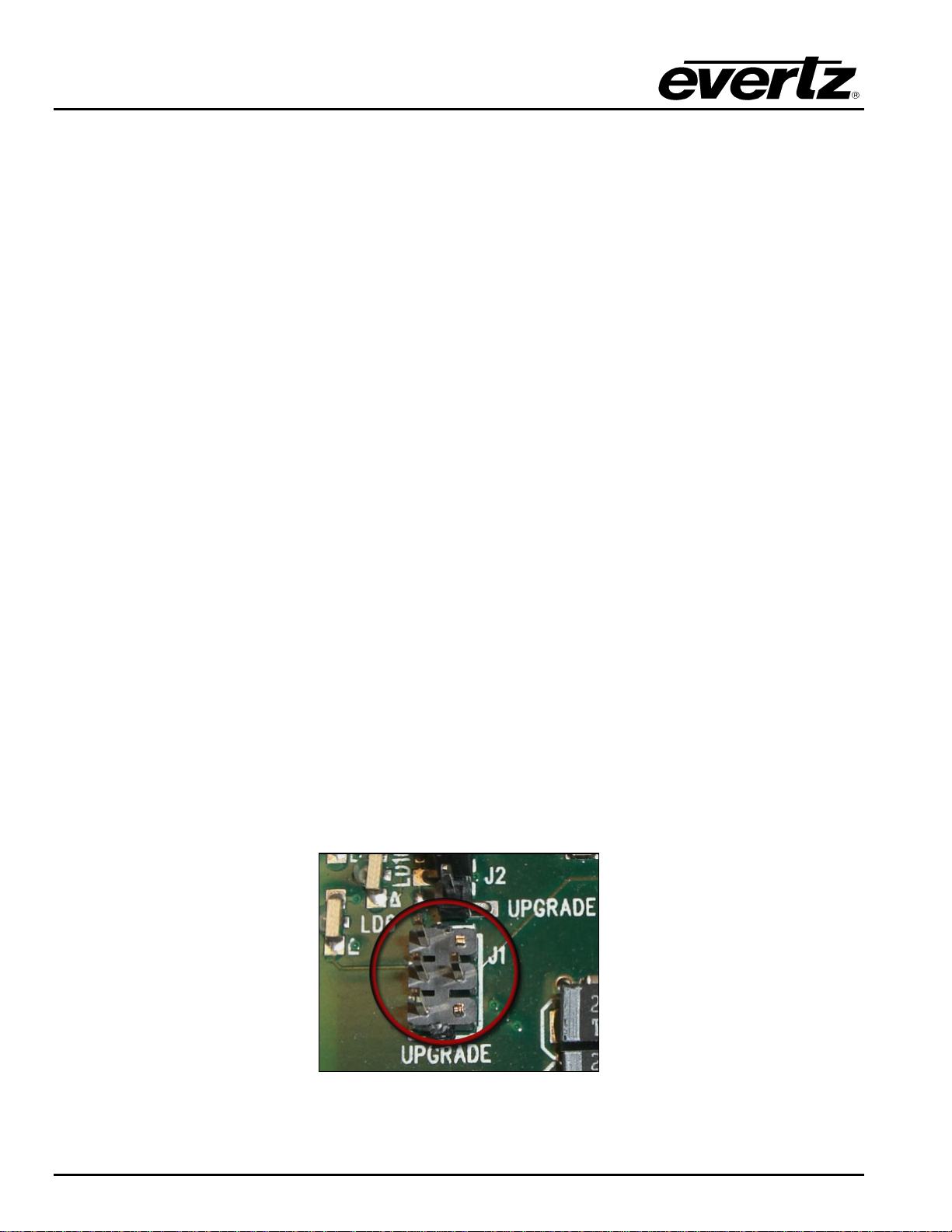
6. PERFORMING A FIRMWARE UPGRADE................................................................................... 16
6.1. FTP PROCEDURE............................................................................................................... 16
6.2. SERIAL PROCEDURE ........................................................................................................ 16
7. VISTALINK®REMOTE MONITORING/CONTROL ...................................................................... 18
7.1. WHAT IS VISTALINK®? ...................................................................................................... 18

7700 MultiFrame Manual
7700PTX-PB Pro-Bel Protocol Translator
Revision 1.4
Figures
Figure 1-1: Typical 7700PTX-PB Setup ...........................................................................................................1
Figure 2-1: PTX Card Edge..............................................................................................................................2
Figure 4-1: Upgrade Jumper ............................................................................................................................4
Figure 4-2: ‘Connect To’ Window.....................................................................................................................5
Figure 4-3: COM1 Properties ...........................................................................................................................6
Figure 4-4: HyperTerminal Main Menu.............................................................................................................7
Figure 4-5: 7700PTX Back Plate......................................................................................................................9
Figure 4-6: RS-232 Pins.................................................................................................................................10
Figure 4-7: RS-422 Pins.................................................................................................................................11
Figure 4-8: UMD Peer Configuration..............................................................................................................13
Figure 5-1: Pro-Bel Status..............................................................................................................................14
Figure 5-2: UMD Peer Status .........................................................................................................................15
Tables
Table 4-1: 7700PTX-PB Main Menu.................................................................................................................7
Table 4-2: Serial Port Parameters....................................................................................................................8
Table 4-3: RS-232 Wiring...............................................................................................................................10
Table 4-4: RS-422 Wiring...............................................................................................................................11
Table 4-5 : Device Number to Display ID Mapping........................................................................................12
Table 4-6: UMD Text Selection ......................................................................................................................13

7700 MultiFrame Manual
7700PTX-PB Pro-Bel Protocol Translator
Revision 1.4
REVISION HISTORY
REVISION DESCRIPTION DATE
1.0 First Release Apr 07
1.1 Updated card edge drawing Nov 07
1.2 Added features, block diagram, technical specs & VistaLINK®section. Nov 08
1.3 Removed references to GPI, GPO, LTC specifications Apr 09
1.4 Removed block diagram Nov 09
Information contained in this manual is believed to be accurate and reliable. However, Evertz assumes no responsibility for the use thereof nor
for the rights of third parties, which may be affected in any way by the use thereof. Any representations in this document concerning
performance of Evertz products are for informational use only and are not warranties of future performance, either expressed or implied. The
only warranty offered by Evertz in relation to this product is the Evertz standard limited warranty, stated in the sales contract or order
confirmation form.
Although every attempt has been made to accurately describe the features, installation and operation of this product in this manual, no
warranty is granted nor liability assumed in relation to any errors or omissions unless specifically undertaken in the Evertz sales contract or
order confirmation. Information contained in this manual is periodically updated and changes will be incorporated into subsequent editions. If
you encounter an error, please notify Evertz Customer Service department. Evertz reserves the right, without notice or liability, to make
changes in equipment design or specifications.

7700 MultiFrame Manual
7700PTX-PB Pro-Bel Protocol Translator
Revision 1.4
This page left intentionally blank

7700 MultiFrame Manual
7700PTX-PB Pro-Bel Protocol Translator
Revision 1.4 7700PTX-PB - 1
1. OVERVIEW
The 7700PTX Universal Protocol Translator module provides an interface between third-party and Evertz
equipment. The 7700PTX communicates with third-party equipment either via one of four serial ports or
via a built in Ethernet port. These ports can provide bi-directional protocol support.
Function:
The function of the 7700PTX generally falls into one of 4 categories:
1. Third-Party Router Control: In this mode the 7700PTX affords VistaLINK®the ability to control
and monitor third-party routers. The 7700PTX can convey UMD information to Evertz monitoring
equipment.
2. Third-Party UMD Interface: In this mode the 7700PTX translates third-party UMD protocol data
into a format suitable for Evertz monitoring equipment.
3. Third-Party Switcher Interface: In this mode the 7700PTX extracts tally information from third-
party switchers and translates and conveys that tally information to Evertz monitoring equipment.
4. Third-Party Device Control: In this mode the 7700PTX allows VistaLINK®to control third-party
devices such as satellite controllers.
Features:
•4 serial ports RS232/422 selectable
•Modular, conveniently fits into 7700FR-C 3RU frame
•Frame status trigger
•VistaLINK®- capable for remote monitoring and control via SNMP (using VistaLINK®PRO)
The 7700PTX-PB is a protocol translator that can accept, on any of its serial 4 serial ports, the Pro-Bel
protocols SW-P-06 and SW-P-04. The 7700PTX-PB translates the Pro-Bel protocol to the Image Video
protocol then transmits it over TCP to a UMD peer. Figure 1-1 shows how the 7700PTX-PB is typically
set up.
Figure 1-1: Typical 7700PTX-PB Setup
In this example, the Pro-Bel controller is connected to serial port 1 of the 7700PTX-PB. The 7700PTX-PB
communicates with two PPVs distributed over two MVP chassis.

7700 MultiFrame Manual
7700PTX-PB Pro-Bel Protocol Translator
7700PTX-PB - 2 Revision 1.4
2. CARD EDGE CONTROLS
2.1. DETERMINING CURRENT IP ADDRESS SETTINGS
To read the current IP address during normal operation, press the toggle switch DOWN. The IP address
can be read on the four-character alphanumeric display.
2.2. RESTORING FACTORY DEFAULTS
To restore all settings to factory defaults, apply power to the card while holding the toggle switch UP until
the green LED is illuminated.
2.3. CARD EDGE LEDS
LED 22 is illuminated when Ethernet activity is detected.
All other card edge LEDs are for factory use only.
LED 15 LED 12
LED 19LED 13LED 20LED 14
LED 22
Red Gr
LED 7LED 2LED 8LED 3 LED 1
Toggle
P
T
X
Figure 2-1: PTX Card Edge

7700 MultiFrame Manual
7700PTX-PB Pro-Bel Protocol Translator
Revision 1.4 7700PTX-PB - 3
3. TECHNICAL SPECIFICATIONS
3.1. DATA INPUT SERIAL PORT
Number of Ports: 4 RS-232 or 3 RS-422
Connector: Phoenix Terminal Block pins
Baud Rate: Up to 1Mbaud
3.2. ELECTRICAL
Voltage: +12V DC
Power: < 6W
Safety: ETL Listed, complies with EU safety directives
EMI/RFI: Complies with FCC Part 15, Class A
EU EMC Directive
3.3. PHYSICAL
Number of slots: 2

7700 MultiFrame Manual
7700PTX-PB Pro-Bel Protocol Translator
7700PTX-PB - 4 Revision 1.4
4. CONFIGURATION
4.1. CONFIGURATION STEPS
The basic steps required to configure the 7700PTX-PB are as follows:
1. Connect a PC running a console application to the PTX debug/monitor port via the adapter cable.
2. Configure the network parameters of the 7700PTX-PB.
3. Configure the parameters of each serial port to match those of the connected Pro-Bel equipment.
4. Configure the Pro-Bel protocol parameters should changes to the defaults be required.
5. Configure the IP address and TCP port of the UMD peer(s).
6. Save all configuration parameters.
7. Power off the 7700PTX-PB.
8. Physically wire the serial port(s) of the 7700PTX-PB to the Pro-Bel equipment.
9. Power on the 7700PTX-PB.
4.2. DEBUG/MONITOR PORT CONNECTION
The 7700PTX-PB is configured via the debug/monitor port, the header of which is labelled J1. A special
Evertz adapter cable allows this port to connect to the COM port of a personal computer. The following
steps describe this procedure.
1. Locate the small, keyed, four–pin end of the upgrade cable provided by Evertz.
2. Connect it to the four-pin interface (J1) near the front of the 7700PTX, directly above the card
unlock latch.
Figure 4-1: Upgrade Jumper

7700 MultiFrame Manual
7700PTX-PB Pro-Bel Protocol Translator
Revision 1.4 7700PTX-PB - 5
3. Connect the other end of the upgrade cable to a straight-through serial cable. Connect the serial
cable to the serial or COM port of the computer.
4. Initiate HyperTerminal on your computer by selecting:
“Start\Programs\Accessories\Communications\HyperTerminal”.
5. Enter a name for your connection, for example: PTX.
6. Press the <Enter> key. A new “Connect To” window opens.
Figure 4-2: ‘Connect To’ Window
7. Select COM1 for the “Connect using’ setting. If COM1 is in use, choose an alternate COM port.
8. Press the <Enter> key or select OK. This opens the “COM Properties” window as shown in Figure
4-3.

7700 MultiFrame Manual
7700PTX-PB Pro-Bel Protocol Translator
7700PTX-PB - 6 Revision 1.4
Figure 4-3: COM1 Properties
9. Enter the information as listed in Figure 4-3.
10. Press the <Enter> key or select OK. The “COM Properties” window closes, leaving the
HyperTerminal window open.
11. Apply power if the 7700PTX-PB does not have power. The boot sequence and Main Menu are
displayed in the HyperTerminal window.
12. If the 7700PTX-PB has power, press the <Enter> key to view the 7700PTX-PB’s menu system.
13. Various 7700PTX-PB parameters are configurable via the 7700PTX-PB’s menu system, the root of
which is called Main Menu.

7700 MultiFrame Manual
7700PTX-PB Pro-Bel Protocol Translator
Revision 1.4 7700PTX-PB - 7
Figure 4-4: HyperTerminal Main Menu
4.3. MAIN MENU
Table 4-1 lists the entries available in the 7700PTX-PB’s Main Menu.
Entry Item Notes
1 Network
Configuration IP address, subnet mask, gateway, etc.
2 Serial Port Setup Baud rate, number of data bits, etc. of serial ports that are connected to
Pro-Bel equipment.
3 Pro-Bel Protocol
Settings Setup Parameters pertaining to the Pro-Bel protocol.
4 Under Monitor
Display Setup IP address and TCP port of UMD peers.
5 Engineering/Debug Used for troubleshooting.
Table 4-1: 7700PTX-PB Main Menu

7700 MultiFrame Manual
7700PTX-PB Pro-Bel Protocol Translator
7700PTX-PB - 8 Revision 1.4
4.4. NETWORK CONFIGURATION
1. From the Main Menu select Network Configuration.
2. If DHCP (Dynamic Host Configuration Protocol) is desired, then the Use DHCP field is set to True.
Otherwise, the IP address, subnet mask, and gateway (if any) are set and the Use DHCP field is
set to False.
3. Once the network settings are configured, select Save and Exit before exiting the Network
Configuration to save the settings, otherwise select Exit.
"The 7700PTX-PB must be rebooted for any network setting changes to take effect.
4.5. SERIAL PORT SETUP
4.5.1. Parameters
The 7700PTX-PB has 4 serial ports. The parameters associated with each serial port are listed in Table
4-2.
Parameter Special Notes
Baud Rate
Data Bits
Parity
Stop Bits
Standard For serial port 4, only RS-232 is valid.
Table 4-2: Serial Port Parameters
"
The serial port settings of the 7700PTX-PB must match those of the Pro-Bel
equipment. The 7700PTX-PB must be rebooted for any serial parameter changes to
take effect.

7700 MultiFrame Manual
7700PTX-PB Pro-Bel Protocol Translator
Revision 1.4 7700PTX-PB - 9
4.5.2. Back Plate
Figure 4-5: 7700PTX Back Plate

7700 MultiFrame Manual
7700PTX-PB Pro-Bel Protocol Translator
7700PTX-PB - 10 Revision 1.4
4.5.3. RS-232 Wiring
Figure 4-6 shows which pins of the back plate are used for RS-232 serial connections.
Figure 4-6: RS-232 Pins
Table 4-3 outlines how to connect the 7700PTX-PB to the Pro-Bel equipment for RS-232 operation.
7700PTX-PB Pro-Bel Equipment
Port Pin Name Pin Pin Name
TXA 1 RX
RXA 2 TX
GND 6 GND
1
TXB 7 RX
RXB 8 TX
GND 12 GND
2
TXC 13 RX
RXC 14 TX
GND 22 GND
3
TXD 23 RX
RXD 24 TX
4 GND 26 GND
Table 4-3: RS-232 Wiring

7700 MultiFrame Manual
7700PTX-PB Pro-Bel Protocol Translator
Revision 1.4 7700PTX-PB - 11
4.5.4. RS-422 Wiring
Figure 4-7 displays which pins of the back plate are used for RS-422 serial connections.
Figure 4-7: RS-422 Pins
Table 4-4 outlines how to connect the 7700PTX-PB to the Pro-Bel equipment for RS-422 operation.
7700PTX-PB Pro-Bel Equipment
Port Pin Name Pin Pin Name
TX-A 1 RX-
TX+A 3 RX+
RX-A 2 TX-
RX+A 4 TX+
1
GND 6 GND
TX-B 7 RX-
TX+B 9 RX+
RX-B 8 TX-
RX+B 10 TX+
2
GND 12 GND
TX-C 13 RX-
TX+C 15 RX+
RX-C 14 TX-
RX+C 16 TX+
3
GND 22 GND
Table 4-4: RS-422 Wiring
"The 7700PTX-PB’s fourth serial port is not RS-422 capable.

7700 MultiFrame Manual
7700PTX-PB Pro-Bel Protocol Translator
7700PTX-PB - 12 Revision 1.4
4.6. PRO-BEL PROTOCOL SETUP
4.6.1. Refresh Cycle Count
The Pro-Bel equipment will send protocol messages to the 7700PTX-PB on a continuous basis. There
may not be any changes in the contents of these messages. A message count can be specified when, in
the absence of changes, the 7700PTX-PB will refresh the PPV(s) UMD data. By default, this message
cycle count is set to 50. If the 7700PTX-PB needs to refresh the PPV(s) more frequently a smaller count
should be selected. If the 7700PTX-PB needs to refresh the PPV(s) less frequently a larger count should
be selected.
4.6.2. Display ID Offset
This is the value added to Pro-Bel’s device number to obtain the display ID which the 7700PTX-PB
transmits to the PPV(s). Table 4-5 shows the default display ID offsets. Although 0 – 31 have been
allocated, Pro-Bel control software currently uses device numbers 1 – 16.
Pro-Bel Device
Number Serial Port 1
(Offset = 0)
Display ID
Serial Port 2
(Offset = 32)
Display ID
Serial Port 3
(Offset = 64)
Display ID
Serial Port 4
(Offset = 96)
Display ID
0 0 32 64 96
1 1 33 65 97
2 2 34 66 98
3 3 35 67 99
4 4 36 68 100
5 5 37 69 101
6 6 38 70 102
7 7 38 71 103
8 8 40 72 104
9 9 41 73 105
10 10 42 74 106
11 11 43 75 107
12 12 44 76 108
13 13 45 77 109
14 14 46 78 110
15 15 47 79 111
16 16 48 80 112
17 17 49 81 113
18 18 50 82 114
19 19 51 83 115
20 20 52 84 116
21 21 53 85 117
22 22 54 86 118
23 23 55 87 119
24 24 56 88 120
25 25 57 89 121
26 26 58 90 122
27 27 59 91 123
28 28 60 92 124
29 29 61 93 125
30 30 62 94 126
31 31 63 95 127
Table 4-5 : Device Number to Display ID Mapping

7700 MultiFrame Manual
7700PTX-PB Pro-Bel Protocol Translator
Revision 1.4 7700PTX-PB - 13
4.6.3. UMD Text Selection
The setting permits the 7700PTX-PB to select only certain parts of the received UMD text.
Setting Description
All characters Use all characters of the received UMD text.
First 8 characters Use only the first 8 characters of the received UMD text.
Last 8 characters Use only the last 8 characters of the received UMD text
Table 4-6: UMD Text Selection
4.7. UNDER MONITOR DISPLAY SETUP
Suppose we have the setup of Figure 4-8:
Figure 4-8: UMD Peer Configuration
Where:
•A Pro-Bel device is connected to Serial Port 1 of the 7700PTX-PB.
•The 7700PTX-PB communicates with a PPV with IP address 192.168.18.50, configured to listen for
Image Video UMD data on TCP port 9800
•Via the debug console Main Menu/Under Monitor Display Peer Setup/UMD Peer Setup via Ethernet 1,
configure peer 1 IP address as 192.168.18.50, and its TCP port as 9800.
"The 7700PTX-PB must be rebooted for any UMD peer changes to take effect.

7700 MultiFrame Manual
7700PTX-PB Pro-Bel Protocol Translator
7700PTX-PB - 14 Revision 1.4
5. TROUBLESHOOTING TIPS
5.1. CHECKING PRO-BEL COMMUNICATION
1. From the Main Menu select Engineering/Debug.
2. Select Show task statistics.
3. There are four entries, one for each serial port, listed under the heading router protocol PCB
stats… If the item pk rx is reported as a non-zero hexadecimal value then the 7700PTX-PB is
receiving data from the Pro-Bel equipment. If it is consistently reported as 0x00000000 then
the 7700PTX-PB is not receiving data from the Pro-Bel equipment. In this case the serial
settings or wiring may be incorrect or the Pro-Bel equipment may not be configured properly.
Figure 5-1: Pro-Bel Status

7700 MultiFrame Manual
7700PTX-PB Pro-Bel Protocol Translator
Revision 1.4 7700PTX-PB - 15
5.2. CHECKING UMD COMMUNICATION
1. From the Main Menu select Engineering/Debug.
2. Select Show task state.
3. There are up to 12 UMD peer entries listed under the heading UMD peer status… A status
reported as ready indicates the 7700PTX-PB is able to communicate with that UMD peer. A
status consistently reported as something other than ready indicates the inability of the
7700PTX-PB to communicate with that UMD peer. Be sure that the UMD peer has been
rebooted after being configured to receive the Image Video over TCP.
4. Figure 5-2 shows that the 7700PTX-PB is able to communicate with the UMD peer whose IP
address is 192.168.18.40 and who is listening on TCP port 9800.
Figure 5-2: UMD Peer Status

7700 MultiFrame Manual
7700PTX-PB Pro-Bel Protocol Translator
7700PTX-PB - 16 Revision 1.4
6. PERFORMING A FIRMWARE UPGRADE
There are two ways to upgrade PTX firmware:
1. Using FTP to perform the upgrade via TCP/IP. (recommended procedure)
2. Using a terminal application such as HyperTerminal to perform the upgrade via a serial connection.
6.1. FTP PROCEDURE
1. Open a command prompt window (in Windows: Start/Programs/Accessories/Command Prompt)
2. Enter the location of the firmware file. For example, type cd c:\temp.
3. Enter the command ftp followed by the PTX IP address.
For example, type ftp –A 192.168.18.22.
4. Enter the FTP command put followed by the firmware file name. For example, put ptx.bin.
5. When the transfer is complete enter the FTP command: bye.
6. Step 5 begins the process of saving the firmware to the non-volatile flash of the PTX. The save
process is displayed as a percentage on the PTX LCD. Once the process is complete, the PTX
LCD again displays the product name and firmware version.
7. Power off the PTX.
8. Power on the PTX.
6.2. SERIAL PROCEDURE
1. Power off the PTX.
2. Connect an adapter cable to a PC running a console or terminal application, such as Windows
HyperTerminal, to the PTX debug/monitor port.
3. Configure the port settings of the terminal program as follows:
Baud 115200
Parity no
Data bits 8
Stop bits 2
Flow Control None
4. Set the PTX run/upgrade jumper to the upgrade position.
5. Power on the PTX.
6. After a few moments, the prompt PPCBOOT> will appear. Enter the command upload.
Other manuals for 7700 Series
127
This manual suits for next models
1
Table of contents
Other evertz Electronic Dictionary manuals

evertz
evertz 7700 Series User manual

evertz
evertz 7700 Series User manual

evertz
evertz 7700 Series User manual

evertz
evertz 570NAT-HW-X19 User manual

evertz
evertz 7700 Series User manual

evertz
evertz MultiFrame EMX3 User manual

evertz
evertz 7700 Series User manual

evertz
evertz 7880IPG-NAT Series User manual

evertz
evertz 7700 Series User manual