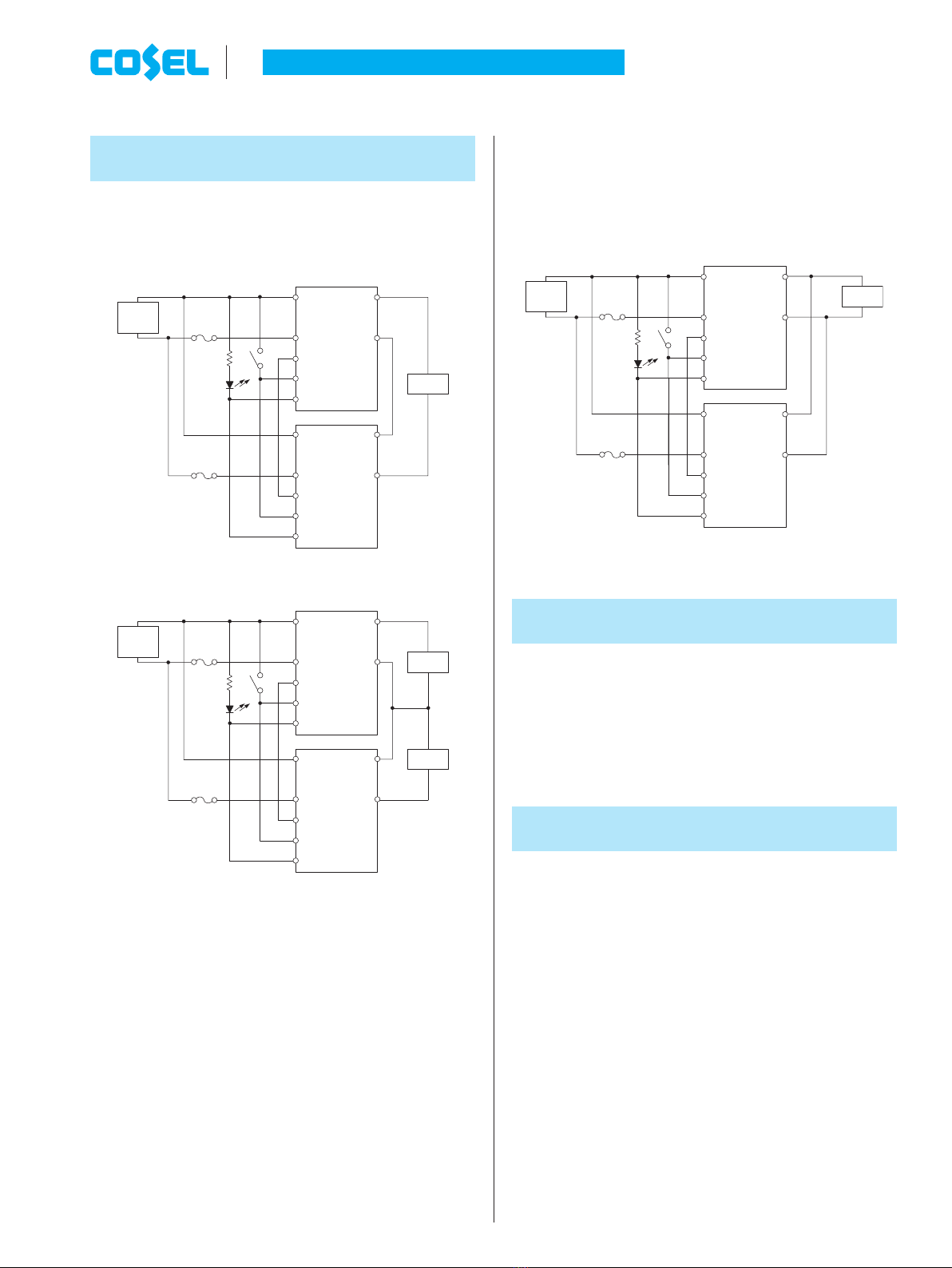
¡In order to use the power supply, it is necessary to wire as shown
in Fig.1.1.
¡When remote ON / OFF function is not used, please open RC pin
or short between RC and -Vin pin.
¡When alarm function is not used, please open ALM pin.
¡In parallel and series operation, connect each PO pin mutually.
When PO function is not used, please open PO pin.
¡The SFS / SFCS series handles only the DC input.
Avoid applying AC input directly.
!! It will damage the power supply. !!
¡Operate with the convection or forced air cooling.
[ Reference : “Derating” ]
1
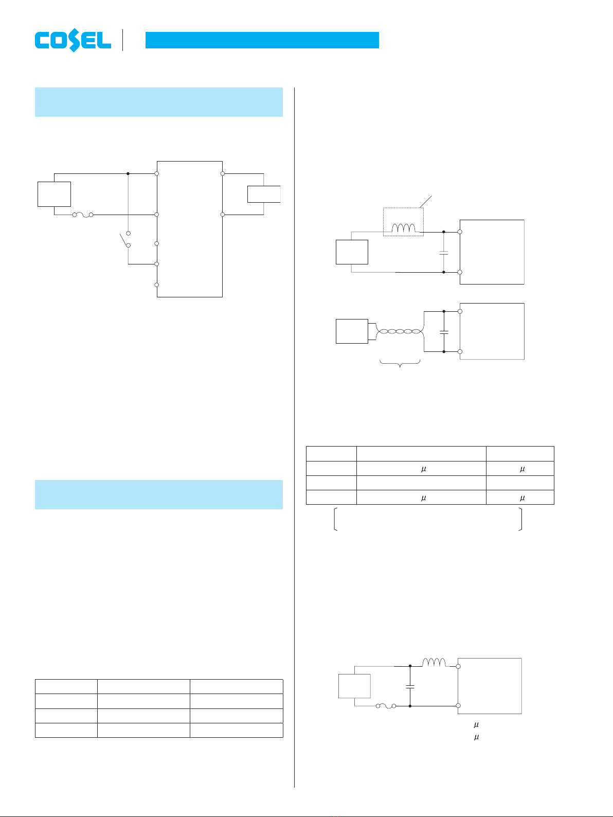
Connection for Standard Use
(2) External capacitor on the input side
¡When the distance from the DC line to the unit is greatly extended,
it makes the input feedback noise much higher and the input volt-
age several times higher than the normal level when turned ON. If
this happens, the output power also becomes unstable. In order to
prevent the unit form failing in this way; please connect Ci to the
input pin. In addition, when the lter with “L” is used, please Ci to
the input pin.
(a)
(b)
Ta=-20 to +85CElectrolytic or Ceramic capacitor
Ta=-40 to +85CCeramic capacitor
Note:
When input line inductance becomes excessively high due to inser-
tion of choke coil, operation of the unit could become unstable. In
this case, increase Ci value more than the value indicated above.
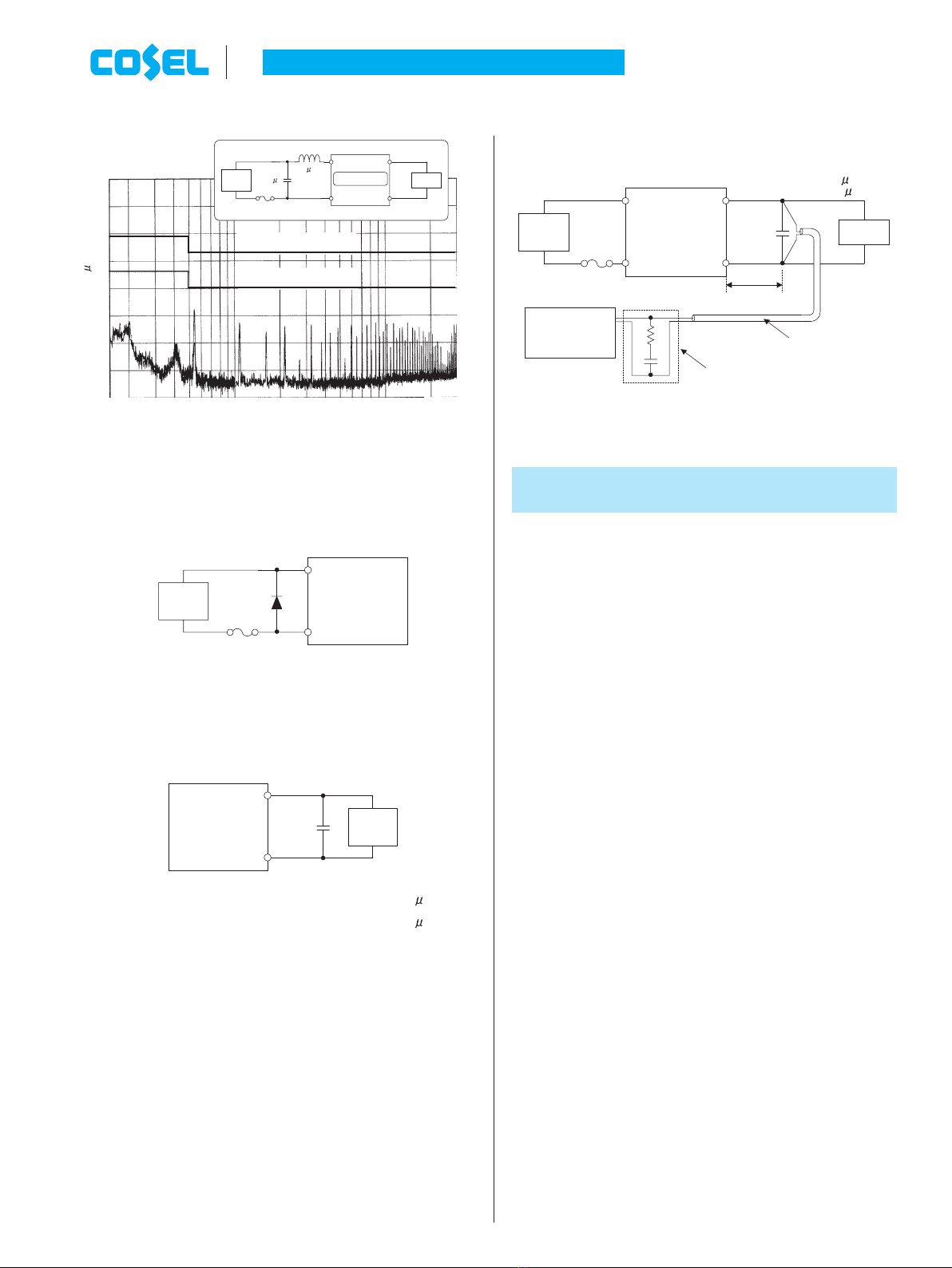
(3) Conducted noise
¡Install an external input lter as shown in Fig.2.2 in order to re-
duce conducted noise.
The result for this solution is shown in Fig.2.3.
C1 : 1 F(ceramic capacitor)
L1 : 1 H
2
Wiring Input/Output Pin
2.1 Wiring input pin
(1) External fuse
¡The SFS / SFCS series is not internally fused. To ensure safe op-
eration and to receive each Safety Standards approvals, please
install an external fuse (fast-blow type).
¡When the input voltage from a front end unit is supplied to multiple
units, install a fast-blow type fuse in each unit.
¡Fuse must be connected to the +Vin side if to -Vin side is used as
ground, or fuse must be connected to -Vin side if +Vin side is used
as a ground.
DC-DC Converters PCB Mount Type Instruction Manual
Fig.1.1 Connection for standard use
Model SFS1524 / SFCS1524 SFS3024 / SFCS3024
Rated current 2A 4A
Model
SFS1048/SFS1548/SFCS1548 SFS2048/SFS3048/SFCS3048
Rated current 1A 2A
Table 2.1 Recommended fuse (fast-blow type)
Fig.2.1 Connection method of capacitor at input pin
Model SFS1524 / SFCS1524
SFS3024/SFCS3024
Ci 33 F 68 F
Model
SFS1048/SFS1548/SFS2048/SFCS1548 SFS3048/SFCS3048
Ci 10 F 22 F
Fig.2.2 Recommended external input lter
Table 2.2 Recommended capacitance Ci
+Vin
RC
PO
ALM
-Vin
DC
Input
+Vout
-Vout
Load
SW
Fuse
+Vin
-Vin
DC
Input
L
high impedance source
Ci
+Vin
-Vin
Ci
DC
Input
C1
+Vin
-Vin
DC
Input
SFS/SFCS-20 June 26, 2020