Iseki GLS 550 H User manual

1
Instruction manual
GLS 550 H

2
To our customer
Read this manual before using your collector. This manual provides the information necessary for operating your tractor
safely and properly.
For safe operation, it is important to read and understand this manual in which you will find all safety precautions to be
taken. Therefore, all safety instructions should be observed during operation.
The collector that you have purchased has been manufactured carefully and in order to gives you the most
satisfaction. As with every mechanical engine, it needs to be cleaned and taken care of. Lubricate it as indicated.
Follow the safety instructions you will find in this manual and on the safety decals on the collector, the mower and
the tractor.
Call on your ISEKI dealer for maintenance, original ISEKI spare parts and for any questions you might have. Use
only ISEKI spare parts. The use of other than genuine ISEKI spare parts might void any liability and warranty by
ISEKI. Please note the model number and the serial number on the dots.
MODEL: ..............................
SERIAL NUMBER: ................................
Give this information to your ISEKI dealer when ordering parts. It is the company policy to improve the products
whenever it is possible and practical to do so. We reserve the right to modify and improve our products at any time
without recurring any obligation to make such changes on products manufactured previously.
Therefore, illustrations might vary slightly for your tractor because of such modifications made before manufactur-
ing your tractor.
Reference to right and left sides or to front and rear of the tractor are determined by facing forward while sitting in
the operator’s seat.

3
SAFETY
* Check if the machine is in good working condition before operating it.
* Check if all safety covers, screens, lids and the suction tube are in place and in good state.
* Periodically checks the torque of all fasteners.
* Never modify the tractor engine tuning; do not boost the engine.
* Do not operate the machine in areas where you cannot keep other persons or animals at a
distance at which they cannot be hurt by projecting objects.
* If your tractor is equipped with a ROPS device, wear a safety belt.
* Do not allow passengers on the tractor.
* Check if nobody or nothing is standing behind you when driving backwards.
* When climbing up a slope, does it as slowly as possible. Never stop or start abruptly on slopes.
* The tractor will have a totally different centre of gravity when equipped with a collector, which diminishes
its operating capacity on slopes. Do not climb a slope when the collector is full.
* Reduce your speed on slopes and when turning sharply in order to avoid loss of control.
* Be careful not to let slip the machine sideways when travelling along soft shoulders or ditches.
* Be on your guard for holes or other folds in the surface when working in bumpy areas.
* Disengage the mower and the collector, stop the engine, apply the parking brake, remove the
starter key and wait until the complete stop of the moving components, before servicing the tractor.
* Do not allow anyone in the driver’s seat when servicing the tractor.
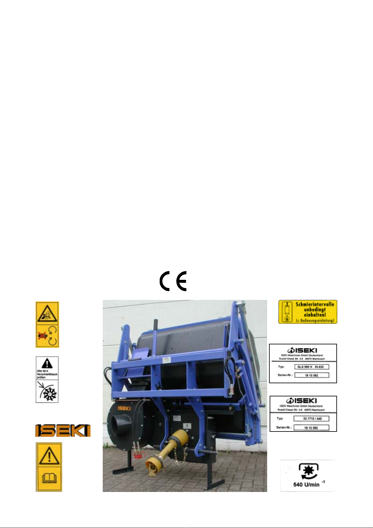
In some of the illustrations shown in this manual, safety covers, panels, lids or even the suction tube
may have been removed for clarity. Never operate the machine without these safety devices.
* Learn how to stop the machine in case of emergency. Read this manual together with the manual of the tractor and
the mower.
* Never authorise another person to operate the machine without him/her having read and understood the manual.
* Never authorise children to operate the machine.
* Always wear appropriate and tight fitting clothing to avoid clothes being dragged into the moving parts of the machine.
* Always wear protective devices for your head, your eyes, your ears, your hands and your feet during operation.
* Thoroughly inspect the area where the machine is to be used and remove all stones, sticks and other debris that
might be projected thus causing injuries or damages.
* Operate the machine only in daylight or using a good light source.
* Check if the safety decals are in place and well legible.

4
DANGER
ATTENTION
The warning IMPORTANT is used in this manual in order to attract your attention to the possibility of component
damage if the instructions are not followed. The warnings WARNING, ATTENTION and DANGER are
used – together with a safety alert symbol (a triangle with an exclamation point) in order to indicate the
degree of danger for your safety.
This safety alerts symbol is used to make you aware of danger: your safety is involved.
Identifies safe operation practices or indicates unsafe conditions that could result in personal injury.
Describes a condition where failure to follow the instructions could result in severe personal injury or death.
Designates a condition where failure to follow the instructions or to heed the warning will most likely result
in severe personal injuries or death.

5
TO THE ISEKI DEALER
•The ISEKI dealer is responsible for the assembly, the installation and the start up of the collector.
•Read this manual and the safety instructions carefully. Check the pre-delivery and the delivery
checklist below for eventual modifications and adjustments before delivery.
PRE-DELIVERY CHECKLIST
•Check the mountings and state of all safety covers, screens and safety devices.
•Check the mounting and legibility of the safety decals. Replace if necessary.
•Check all fasteners and torque as described in the chart at the end of the manual for the values are not indicated.
•Lubricate all grease nipples.
•Check the correct functioning of the machine.
DELIVERY CHECKLIST
•Show the customer how to put the tuning.
•Explain the importance of lubrication and show the lubrication points.
•Show all safety switches, screens, safety devices, lids and their options.
•Hand the manual to the customer, and ask him to read and understand it thoroughly.
•Explain the customer that this machine can only be driven on a public road if it is equipped in
compliance with the applicable traffic regulations.

6

7
Equipment
33.1713
Blower with fan D 440, incl.shaft f. 3 pnt , Universal joint, PTO cover, Intake blower, Flexible and Inlet,
fitting on. GLS 550 (Low-dump), Manual
30.620
Grass- and leafcontainer GL 550 H, incl.2 in a frame mounted Containerparts, Hydr.-cylinder, 2 liftarms,
2 Parallel hook, closing system, Gasspring, canal, net, cover
Options
Tube with mower outlet for Front- and Midmountmower
Accesories For Manual work
Accesories for leafcontainer LS 100
Technical Data
Lenght Height Width Blower Housing RPM Dump.Height
950 1300 1500 110 kg 170 kg 540 U/min 1,90/2,00 m
Manufacturer
RPM
ID.plate

8
Mounting of the collector on the tractor
Preparation
Put the liftarm in the correct position.
For the Tractors: TM-TF liftarm in the leftposition (driverseat) en secure with a pin.
For all other tractors put the liftarm to the right (driverseat ) and secure with a pin.
Slowly back up the tractor to the container and stop the engine
Connect the liftarms with the tractor and secure
Connect the upperlink , make sure that the collector is in a straight position .
Connect PTO.
Connect hydraulic.
Preparation of the tractor
Equipe the tractor with the double acting valve.Tyre pressures need to have same values..The
3 point linkage need to be adjusted.
PTO rpm need to be 540 rpm
Assembly - Start up
The container will be delivered in 3 parts
1. Blower
2. Frame
3. Box wit plastic parts
The assembly is written uderneath. Assembel the container on a flat surface , floor.

9
Removing the blower
To remove the blower work in opposite way
Important
Important
Be sure to connect correctly the universal joint ; serious damage may be the result if the
universal joint is too long .Make sure that the universal joint is not too short this could cause
injuries and risk of mall functioning
Universal joint lenght
Move the TXG to the collector. Take the universal joint and put the 2 parts near each other.
The shaft may not be longer then the distance between tractor and collector. The overlap of
the universal joint should be 60mm.
How to cut the universal joint?
Both parts ,of the profile and protection, need to be cut in the correct lenght.
Apply grease on the profile and slide both parts together
Mount the universal joint
Attention: USE ONLY THE DELIVERED UNIVERSAL JOINT. APPLY REGULARY GREASE
The rear door need to be closed . All operation levers in neutral.
Make sure that the 3 point linkage is in the correct position.
Be aware for injuries by assembly or disassembly.
Don‘t allow any person between tractor and collector.

10
Transport
The tractor and collector may only be transported in empty conditions
For transport on a trailer or road use lightening kit.
Emptying of the collector:
Emptying the collector is only possible with the container is in the upper position.
To empty the collector use the handel , or if you installed a cabine use hydraulic valve
The GLS 550 H can not be opened in the lowest position.
Emptying or raising the collector is only possible if the piston is correct
mounted.
Never raise the collector when the tractor is moving . Raising the collector
when the tractor is in motion might cause damages to the collector .
Raise the collector to his highest position and secure , which prevent the
collector from falling down
Maintenance
1. Torque of the fasteners
Check the torque of all fasteners. The bolts and nuts can loosen by vibrations .
2. Universal joint
a) Grease up the universal joint
b) Keep dust free
c) Apply grease to the universal joint profile

11
d) Replace damaged parts immediatley
Hydraulic:
Check the hydraulic hoses . They should not be flattened , worn or torn.
Replace if necessary
Screen/net:
Remove any grass clippings from the screens of the collector. Clean screen will insure good
collecting and complete filling performances
Belt:
Check the state of the belt after the first 8 hours
Afterwards check the tension on the belt every 50 hours
State of the blower
Check the blower fins. They should not be twisted , damaged or dented. A damaged fin could
bring the blower out of balance.
If the blower is out of balance please contact your ISEKI dealer
Cleaning or after every mowing season or once a year
- Clean the entire machine and pay special attention to the components where the clippings can
accumulate: the collector intake, the discharge tube of the blower, the mower shooter and the collector
itself. Eliminate all grass accumulations for they diminish the performance of the machine.
After having cleaned the machine with water, grease up the bearings and engage the blower in order to get
rid of any water that might have accumulated in the blower.
- Check if the blower shaft turns freely and that there is no free play. Replace if necessary.
- Check the hydraulic hoses: they should not be flattened, worn or torn. Replace if necessary.
-Check the transmission oil: empty the oil tank and refill it with new oil. Replace the oil filter, check for any
oil leaks, retighten the leak-off adapter and renew the flexible couplings if necessary.

12
1. Put frame onto the blower.
Put the lift rod in the central position and lock with
6 bolts M12.
Adjust the position of the lift rod according to the
tractor
2. To continue the assembly put the frame on the
tractor
Figure: 1
Figure 2
Assembly

13
3. For Low-Dump you have to mount the canal (figure 3) on the blower . For High-Dump the canal
(figure 4) is packed with the container
Figure 3 Figure 4
4. Mount the rubber joint on the ring and put the ring on the canal
Figure 5 Figure 6

14
5. On both ends of the blower please mount the rubber stopper.
6. Mount the front part of the container on the
frame and at same time mount the hubarms left
and right.
Figure 7
Figure 8

15
7. Adjust both of parallelarms at the same lenght:896-898mm
8. Mount the hydr.cylinder , parallelarm and hubarm on
the U-profile , connect these with a pin.
Figure 9
Foto 10

16
9. Attach the canal and cloth on the support.
As for the cloth you have to drill holes into the container
and fasten with rivets.
10. Bring the container in his highest position to mount the securityplate(figure 12).ATTENTION: secure
the container (figure 13). The securityplate is working trough the hydr.cylinder.
Mount the plate so that when the container is up ,the plate is closing the canal ,en when we lower the
container the canal is free.
Figure 11
Figure 12 Figure 13

17
11. Mount on the door the hinges
12. Mount the door with hinges on the main frame
Figure 14 Figure 15
Figure 16 Figure 17

18
13. Close the door , Adjust the hooks to keep the door closed, be aware that the door is closed
completely over the total lenght . Then tighten the hinges.
Figure 18 Figure 19
Figure 20
14. Mount on the innerside of the collector the double
gasstrut.

19
Figure 21 Figure 22
Figure 23
16. Mount the doorlocker and make sure that the door is completely closed. Adjust when needed
a.) Pull the arm as far as possible to the lowest
position
b) Adjust the tensionroller
c) Adjust the parallelarms
15. Provide the doorlocker from a tensionroller

20
Figure 25
18. Connect the hydraulic , make sure there are no leaks.
18. Adjust the canal .
Make sure that there is no play between the canal and the
container , tighten the M8 bolts
Figure 26
Figure 24
17. The openingrod need to be mounted ,on both sides ,so that the handel is in the upper position
Table of contents
Popular Farm Equipment manuals by other brands

CynkoMet
CynkoMet N-235 Series Instructions for Use and Operation

GREAT PLAINS
GREAT PLAINS 3P500 Operator's manual

Strautmann
Strautmann Mega Trailer II operating instructions

Maschio
Maschio GASPARDO AIRONE Use and maintenance

HARVEST
HARVEST H13114XT Operator's manual

Prevue Hendryx
Prevue Hendryx 7324 parts list

BE
BE AGRI EASE BE-EFGC F Series Operations & parts manual

aivituvin
aivituvin AIR 25 instruction manual

brielmaier
brielmaier Multi-Twister MT220B Translation of the original instructions

GREAT PLAINS
GREAT PLAINS PL5200 Operator's manual

MS Schippers
MS Schippers Greenline Move Customer service

Grifo
Grifo DMS manual