Iseo Stylos Smart User manual

Stylos Smart
Non contractual document. Subject to change. Cod. 60000STY2SA00.5 - 31/03/2021
Stylos Smart installation guide (EN/IT) - © 2021 Iseo Serrature S.p.a. - www.iseo.com
INSTALLATION GUIDE (EN)
GUIDA INSTALLAZIONE (IT)
ELECTRONIC SUPPORT SERVICE
iseozero1.com
®
iseo.com
Iseo Serrature s.p.a
Via San Girolamo 13
25055 Pisogne (BS)
ITALY
Tel. +39 0364 8821
Download
See the
Tutorial Video
Iseo Argo App
TECHNICAL DATA - DATI TECNICI
app.iseo.com
ARGO
JP
6JP
4JP
2JP
0
J2.
1J2.
2J2.
3J2.
4
JPS
S1
3. CONNESSIONI ELETTRICHE
LEGENDA:
J2.1/2/3/4 = Alimentazione/Lockbus
JPS = Jumper di Sistema (riservato)
S1 = Pulsante di programmazione
JP 0/2/4/6 = Jumpers Indirizzo Bus
La sezione minima/massima dei
cavi di collegamento è :
Lato posteriore
vista circuito
INDIRIZZO 0 =
INDIRIZZO 2 =
INDIRIZZO 4 =
INDIRIZZO 6 =
INDIRIZZO
BUS
(Master)
(slave)
(slave)
(slave)
FUNZIONE
Alimentazione: 8÷30 VDC 3W MAX
(Canale di Comunicazione)
NEGATIVO (-) GND
POSITIVO (+) Alimentazione
LOCKBUS
INDIRIZZO
BUS
0.20÷1.5 mm² (24÷15AWG).
JP
4
JP
2
JP
0
JP
6
}
J2.
1J2.
2J2.
3J2.
4
JP
6
JPS
S1
JP
4JP
2JP
0
LEGEND:
J2.1/2/3/4 = Power supply/Lockbus
JPS = System Jumper (reserved)
S1 = Programming button
JP 0/2/4/6 = Bus Address Jumpers
JP
6JP
4JP
2JP
0
Back side view
Circuit board
J2.
1J2.
2J2.
3J2.
4
JPS
S1
ADDRESS 0 =
ADDRESS 2 =
ADDRESS 4 =
ADDRESS 6 =
BUS
ADDRESS
(Master)
(slave)
(slave)
(slave)
FUNCTION
(Communication Channel)
NEGATIVE (-) GND
POSITIVE (+) Power Supply
LOCKBUS
}
BUS
ADDRESS
JP
4
JP
2
JP
0
JP
6
J2.
1J2.
2J2.
3J2.
4
JP
6
JPS
S1
JP
4JP
2JP
0
3. ELECTRICAL CONNECTIONS
mm²0.20÷1.5
Minimum/maximum cross-section
of the cables is:
(24÷15AWG).
Power supply: 8÷30 VDC 3W MAX
2. DISASSEMBLING - SMONTAGGIO
3
1
4
2
UK: disconnect the power before opening the device.
IT: scollega l’alimentazione prima di aprire il dispositivo.
1. VERSIONS AND DIMENSIONS - VERSIONI E DIMENSIONI
A = 47,5mm
B = 17,5mm
C = 130mm
A = 47,5mm
B = 17,5mm
C = 130mm
A = 40mm
B = 10mm
C = 125mm
C
A
B
Credential reader
with led
Lettore di credenziali
con led
Credential reader
with keyboard
Lettore di credenziali
con tastiera
Spacer for wall
installation
Distanziale per
installazione a muro
Power Supply
:
8÷30 VDC 3W MAX
Operating temperature: -20°C + 60°C
RFID: frequecy 13,553 - 13,567 MHz, maximum magnetic field: 0,89 µA/m (measured at 10m at the
maximum power capacity).
Radio: frequency 2,40 - 2,4835 GHz, maximum power: 5,25 mW
EN
Alimentazione:
8÷30 VDC 3W MAX
Temperatura di utilizzo: -20°C + 60°C
RFID: frequenza 13,553 - 13,567 MHz, massimo campo magnetico: 0,89 µA/m (misurato a 10m alla
massima potenza erogabile).
Radio: frequenza 2,40 - 2,4835 GHz, potenza massima: 5,25 mW
IT
Lithium Battery - Pila al litio
CR2032 - 3V
3V
CR2032
Lithium
Pericolo d’esplosione se la pila è sostituita con altra di tipo errato.
IT
Smaltire separatamente le pile usate seguendo le disposizioni locali.
La sostituzione della pila deve essere effettuata da personale tecnico qualificato.
WARNINGS
Read this manual prior to use the device in order to ensure a safe and proper use.
Preserve this manual as future reference.
The installation and maintanance of the device must be carried out by qualified technical staff, adequately
trained by ISEO.
The instructions should be carefully followed during installation. These instructions and any maintenance
instructions should be passed on by the installer to the user.
No modifications of any kind are permitted, except for those described in these instructions.
The product must be destined only for the use for which it is expressly designed and therefore as a
credential reader for civil and industrial locations. Any other use is considered improper and dangerous.
The electrical connection must be made according to the constructor's instructions and respecting the
regulations in force.
Disconnect the power supply before carrying out any technical service that involves opening or accessing
the internal parts of the product.
In the event of a failure and/or poor operation, remove the power supply using the main switch and do not
tamper with it. For all repairs, exclusively contact a technical assistance center authorized by the constructor.
AVVERTENZE
Leggere il manuale utente prima dell’utilizzo del prodotto al fine di garantire un uso sicuro e corretto.
Conserva questo manuale come riferimento futuro.
L’installazione e la manutenzione del prodotto devono esssere effettuate da personale tecnico qualificato,
adeguatamente addestrato da ISEO.
Le istruzioni devono essere seguite attentamente durante l’installazione. L’installatore deve fornire all’
utente queste istruzioni ed eventuali istruzioni per la manutenzione.
Il prodotto dovrà essere destinato solo all’uso per il quale è stato espressamente concepito e cioè come
lettore di credenziali per ambiente civile e industriale. Ogni altro uso è da considerarsi improprio e pericoloso.
I collegamenti elettrici devono essere fatti secondo le istruzioni del costruttore e nel rispetto delle
normative vigenti.
In caso di guasto e/o cattivo funzionamento, scollegare l'alimentazione utilizzando l'interruttore generale
senza effettuare manomissioni. Per le riparazioni, rivolgersi esclusivamente a un centro di assistenza tecnica
autorizzato dal costruttore.
Scollegare l’alimentazione prima di eseguire qualsiasi intervento tecnico che comporti l’apertura o l’accesso
alle parti interne del prodotto.
Nessuna modifica di alcun tipo è consentita, ad eccezione di quelle descritte in queste istruzioni.
Per la procedura di sostituzione della pila, consulta il manuale utente disponibile al sito app.iseo.com.
EN Risk of explosion if the battery is replaced with an incorrect type.
Dispose of batteries according to your local environmental laws and guidelines.
Battery replacement must be carried out by qualified technical staff.
For the replacement battery procedure, read the user manual available at app.iseo.com.
EC Declarations of conformity available at:
https://www.iseo.com/it/en/download
EC Declarations of conformity available at:
https://www.iseo.com/it/it/download

Non contractual document. Subject to change. Cod. KW14030.0470, Rev. 2 - 21/10/2015
Installation guide Libra Smart (IT/GB/D/F/E) - © 2015 Iseo Serrature S.p.a. - www.iseo.com
4.1 EXCHANGE OF CODED KEYS WITH ACTUATOR: LOCKBUS TYPE SELECTION
4.1 SCAMBIO DELLE CHIAVI CIFRATE CON L’ATTUATORE: SELEZIONE TIPO LOCKBUS
1
Red led
flashing
Led rosso
lampeggiante
4.3 EXCHANGE OF CODED KEYS WITH ACTUATOR: EXCHANGE KEYS
JP
6JP
4JP
2JP
0
J2.
1J2.
2J2.
3J2.
4
JPS
S1
Back side view
Power supply
8
÷
24VDC 25W
COM
NO/NC
GND
IN AN
I/O 2
I/O 1
VCC
GND
L2L1P1 P2 LRL
J P 3
LPW
J P 2L C HJ P 1LV O
V2 Output
V1 Output
OPEN
V PWR +
GND
EARTH
4.3 SCAMBIO DELLE CHIAVI CIFRATE CON L’ATTUATORE: SCAMBIO CHIAVI
UK: for more information regarding the exchange of keys, see the Tutorial Video available at app.iseo.com.
IT: per maggiori informazioni sullo scambio delle chiavi, guarda il VideoTutorial disponibile al link app.iseo.com.
Switch on the Stylos keeping
pressed the button and wait for the
acustic and light signal, then
release it immediately.
Accendi lo Stylos tenendo premuto
il pulsante e attendi il segnale
acustico e luminoso, poi rilascialo
immediatamente.
1
2
Switch on the actuator
keeping pressed one
button for 3 sec.
Accendi l’attuatore
tenendo premuto un
pulsante per 3 sec.
Stylos Master
address 0
Actuator
address 1
Attuatore
indirizzo 1
Stylos Master
indirizzo 0
4.2 EXCHANGE OF CODED KEYS WITH ACTUATOR: JUMPER SETTING
JP
6JP
4JP
2JP
0
J2.
1J2.
2J2.
3J2.
4
JPS
S1
Back side view
Power supply
8
÷
24VDC 25W
COM
NO/NC
GND
IN AN
I/O 2
I/O 1
VCC
GND
L2L1P1 P2 LRL
J P 3
LPW
J P 2L C HJ P 1
LV O
V2 Output
V1 Output
OPEN
V PWR +
GND
EARTH
4.2 SCAMBIO DELLE CHIAVI CIFRATE CON L’ATTUATORE: POSIZIONAMENTO JUMPER
Stylos Master
address 0
Actuator
address 1
Attuatore
indirizzo 1
Stylos Master
indirizzo 0
Switch on the Actuator and check if red led flashes
2 times (lockbus 2).
If it flashes 1 time follow point 2 to change the
lockbus type.
Accendi l’Attuatore e verifica che il led rosso
lampeggi 2 volte (lockbus 2).
Se lampeggia 1 volta segui il punto 2 per cambiare
il tipo di lockbus.
2
Switch on the Actuator keeping pressed both buttons
simultaneously for 1 sec.
Switch on it again to check if now red led flashes 2 times.
If not repeat the procedure.
Accendi l’Attuatore tenendo premuti i pulsanti contempora-
neamente per 1 sec.
Accendilo nuovamente per verificare se ora il led rosso
lampeggia 2 volte. In caso negativo ripetere la procedura.
Set jumpers on Actuator and Stylos as per pictures below. Note this configuration is correct only in case of
1 Stylos (Master) and 1 Actuator (Slave).
Posiziona i jumpers nell’Attuatore e nello Stylos come nelle figure sotto. Notare che questa configurazione è
corretta solo nel caso di 1 Stylos (Master) e 1 Attuatore (Slave).
UK: for more information
about jumper setting with
different configuration, refer
to the user manual available
at app.iseo.com.
IT: per maggiori informazioni
sul posizionamento dei
jumper con configurazioni
differenti, riferisci al manua-
le utente disponibile al link
app.iseo.com.
5.5 INSTALLATION WITH THE SPACER
5.5 INSTALLAZIONE CON IL DISTANZIALE
Take care not to damage
the cables while installing
the device.
Installando il dispositivo
prestare attenzione a non
danneggiare i cavi.
Check the connections on
section 3 before powering
up the device.
Prima di alimentare il
dispositivo verificare le
connessioni descritte nella
sezione 3.
5.4 INSTALLATION WITHOUT THE SPACER
5.4 INSTALLAZIONE SENZA IL DISTANZIALE
Take care not to damage
the cables while installing
the device.
Installando il dispositivo
prestare attenzione a non
danneggiare i cavi.
Check the connections on
section 3 before powering
up the device.
Prima di alimentare il
dispositivo verificare le
connessioni descritte nella
sezione 3.
1
2
5. INSTALLATION ON A METAL PROFILE
5. INSTALLAZIONE SU UN PROFILO METALLICO
Ø 3.2 mm
(max)
Ø 3.2 mm
(max)
Ø 26 mm
3.9 x 19 mm
83
26
5 x 25 mm
3.9 x 30 mm
Ø 5 mm
Ø 26 mm
Ø 5 mm
5.2 INSTALLATION ON A WALL
5.2 INSTALLAZIONE SU UNA PARETE
83
26
Ø 5 mm
Ø 5 mm
3.9 x 30 mm
5.3 INSTALLATION WITH A SPACER ON A WALL
5.3 INSTALLAZIONE CON IL DISTANZIALE SU UNA PARETE
83
5 x 25 mm
Power supply
8
÷
24VDC 25W
COM
NO/NC
GND
IN AN
I/O 2
I/O 1
VCC
GND
L2L1P1 P2 LRL
J P 3
LPW
J P 2L C HJ P 1LV O
V2 Output
V1 Output
OPEN
V PWR +
GND
EARTH
1
2

Stylos Smart
Non contractual document. Subject to change. Cod. 60000STY2SA00.5 - 31/03/2021
Stylos Smart installation guide (FR/ES) - © 2021 Iseo Serrature S.p.a. - www.iseo.com
GUIDE D’INSTALLATION (FR)
GUÍA DE INSTALACIÓN (ES)
ELECTRONIC SUPPORT SERVICE
iseozero1.com
®
iseo.com
Iseo Serrature s.p.a
Via San Girolamo 13
25055 Pisogne (BS)
ITALY
Tel. +39 0364 8821
Download
See the
Tutorial Video
Iseo Argo App
app.iseo.com
ARGO
JP
6JP
4JP
2JP
0
J2.
1J2.
2J2.
3J2.
4
JPS
S1
3. CONEXIONES ELÉCTRICAS
LEYENDA:
J2.1/2/3/4 = Alimentación/Lockbus
JPS = Jumper de sistema (reservado)
S1 = Pulsador de programación
JP 0/2/4/6 = Jumpers Bus dirección
La sección mínima/máxima de los
cables de conexión es:
Lado posterior
vista circuito
DIRECCIÓN 0=
DIRECCIÓN 2=
DIRECCIÓN 4=
DIRECCIÓN 6=
BUS
DIRECCIONES
(Master)
(slave)
(slave)
(slave)
FUNCIÓN
Alimentación: 8 ÷30 VDC 3W MAX
(Canal de comunicaci
ó
n)
NEGATIVO (-) GND
POSITIVO (+)
Alimentación
LOCKBUS
INDIRIZZO
BUS
0.20÷1.5 mm² (24÷15AWG).
JP
4
JP
2
JP
0
JP
6
}
J2.
1J2.
2J2.
3J2.
4
JP
6
JPS
S1
JP
4JP
2JP
0
LEGENDE:
J2.1/2/3/4 = Alimentation/Lockbus
JPS = Jumper du systeme (réservé)
S1 = Bouton de programmation
JP 0/2/4/6 = Jumpers Bus adresse
JP
6JP
4JP
2JP
0
Face arriére
vue cote circuit
J2.
1J2.
2J2.
3J2.
4
JPS
S1
ADDRESS 0 =
ADDRESS 2 =
ADDRESS 4 =
ADDRESS 6 =
BUS
ADRESSE
(Master)
(slave)
(slave)
(slave)
FONCTION
(Canal de Comunication)
NEGATIF (-) GND
POSITIF (+) Alimentation
LOCKBUS
}
BUS
ADRESSE
JP
4
JP
2
JP
0
JP
6
J2.
1J2.
2J2.
3J2.
4
JP
6
JPS
S1
JP
4JP
2JP
0
3. CONNEXION ELECTRIQUE
La section minimum/maximum
du câble de raccordement est:
Alimentation: 8÷30 VDC 3W MAX
0.20÷1.5 mm² (24÷15AWG).
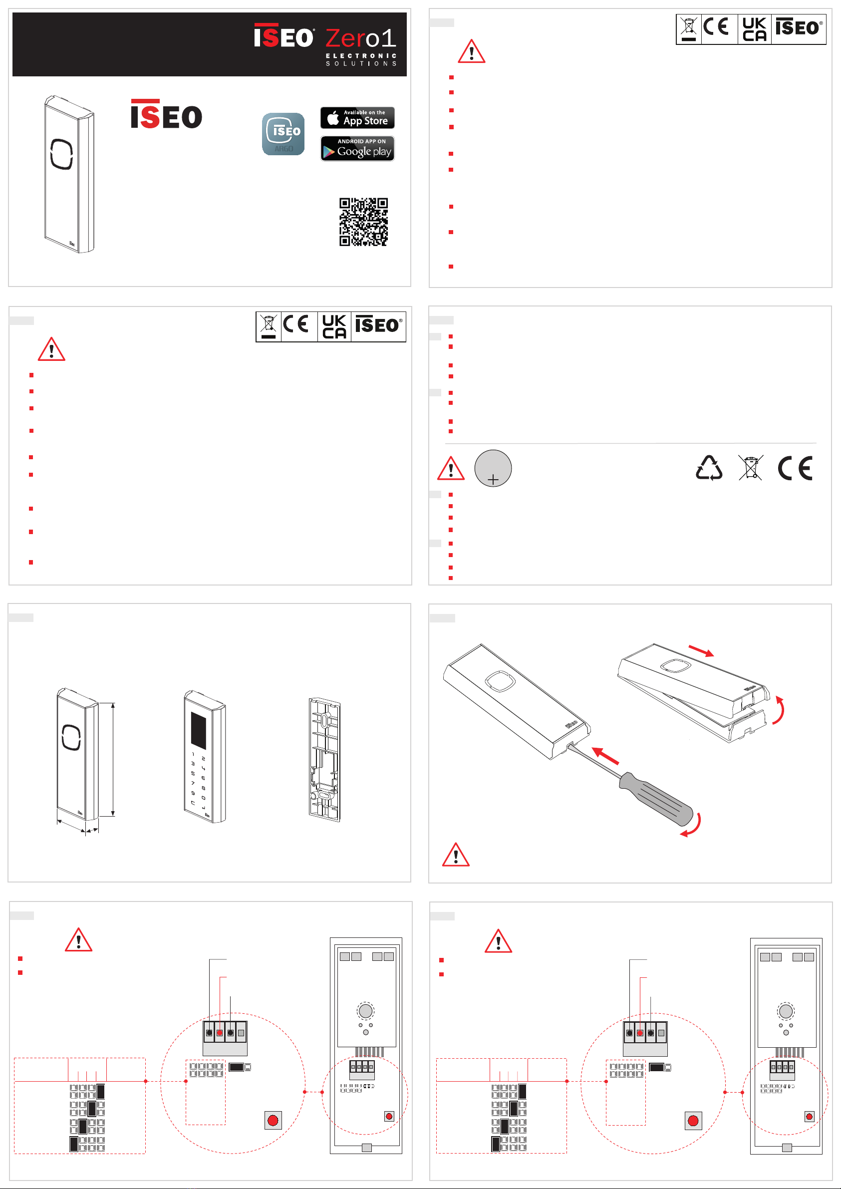
2. DEMONTAGE - DESMONTAJE
3
1
4
2
FR: déconnecter l’alimentation avant d’ouvrir le produit.
ES: desconecte la alimentación antes de abrir el dispositivo
1. VERSIONS ET DIMENSIONS - VERSIONES Y DIMENSIONES
A = 47,5mm
B = 17,5mm
C = 130mm
A = 47,5mm
B = 17,5mm
C = 130mm
A = 40mm
B = 10mm
C = 125mm
C
A
B
Lecteur de badge à LED
Lector de credenciales
Lecteur de badge à clavier
Lector de credenciales
con teclado
Cale de pose pour
installation en applique
Distanciador para
instalación en muro
DONNÉES TECHNQUES - DATOS TÉCNICOS
Alimentation: 8 à 30 VDC 3W
MAX
Température de fonctionnement: -20°C à + 60°C
RFID: fréquence 13,553 - 13,567 MHz, exposition maximale au champ magnétique: 0,89 µA/m (puissance
mesuré à 10m et à la capacité maximale).
Radio: fréquence 2,40 - 2,4835 GHz, puissance maximale: 5,25 mW.
FR
Alimentación:
8÷30 VDC 3W MAX
Temperatura de funcionamiento: -20°C + 60°C
RFID: frecuencia 13,553 - 13,567 MHz, campo magnético máximo: 0,89 µA/m (medido a 10m a la
potencia máxima).
Radio: frecuencia 2,40 - 2,4835 GHz, potencia máxima: 5,25mW
ES
Batterie lithium - Batería de lítio
CR2032 - 3V
3V
CR2032
Lithium
Existe riesgo de explosión si la batería es reemplazada por una incorrecta.
ES
Deseche las baterías de acuerdo con las leyes y directrices medioambientales locales.
El reemplazo de la batería debe ser realizado por personal técnico cualificado.
Para el procedimiento de reemplazo de la batería, lea el manual del usuario disponible en app.iseo.com.
FR Risque d’explosion si la batterie est remplacée par un modèle non approprié.
Eliminer les batteries conformément aux règles et directives environnementales en vigueur dans votre pays.
Le changement des batteries doit être réalisé par du personnel technique qualifié.
Pour réaliser le changement des batteries, veuillez consulter le manuel d’utilisation disponible à l’adresse app.iseo.com.
ATTENTION
Consulter ce manuel avant la mise en service du produit afin d’en permettre un usage sécurisé et convenable.
Conserver ce manuel comme document de référence pour le suivi du produit.
L’installation de ce matériel requiert l’intervention de personnel qualifié, idéalement formé par ISEO.
Les instructions doivent être rigoureusement respectées pendant l’installation. Les instructions et les
différentes modalités de maintenance doivent être transmises par l’installateur à l’utilisateur.
Aucune modification quelque-soit sa nature n’est permisse, à l’exception de celles décrites dans ce document.
Le produit doit être destiné uniquement à l’usage pour lequel il a été expressivement conçu: un lecteur
de badge pour un bâtiment public ou industriel. Tout usage différent sera considéré comme inapproprié
et dangereux.
Les connexions électriques doivent être réalisées en respectant les instructions du constructeur ainsi que
les normes en vigueur.
En cas de dysfonctionnement et/ou de mauvaises opérations, désactiver l’alimentation en utilisant
l’interrupteur général et ce de manière impérative. Pour toutes réparations, contacter exclusivement un
centre d’assistance technique autorisé par le constructeur.
Couper l'alimentation électrique avant toute intervention qui nécessite l'ouverture du produit ou la
manipulation de ces pièces internes.
ADVERTENCIAS
Lea este manual antes de usar el dispositivo para garantizar un uso seguro y adecuado.
Conserve este manual para futuras referencias.
La instalación y el mantenimiento del dispositivo deben ser realizados por personal técnico calificado y debida-
mente capacitado por ISEO.
Las instrucciones deben ser seguidas cuidadosamente durante la instalación. Estas instrucciones y cualquier
instrucción de mantenimiento deben ser transmitidas por el instalador al usuario.
No se permiten modificaciones de ningún tipo, a excepción de las descritas en estas instrucciones.
El producto debe ser destinado únicamente para el uso para el que está expresamente diseñado, por lo
tanto, como un lector de credenciales para ambientes civiles e industriales. Cualquier otro uso se considera
impropio y peligroso.
Las conexiones eléctricas deben realizarse de acuerdo con las instrucciones del fabricante y de acuerdo con
la normativa vigente.
En caso de avería y/o mal funcionamiento, desconecte la alimentación utilizando el interruptor general y no lo
manipule. Para la reparación, contacte exclusivamente con un centro de asistencia técnica autorizado por el
fabricante.
Desconecte la fuente de alimentación antes de realizar cualquier servicio técnico que implique abrir o acceder
a los componentes internos del producto.
EC Declarations of conformity available at:
https://www.iseo.com/it/es/download
EC Declarations of conformity available at:
https://www.iseo.com/it/fr/download

4.1 ECHANGE DES CLEFS CODEES AVEC L’ACTIVATEUR: SELECTION DU TYPE DE LOCKBUS
4.1 INTERCAMBIO DE LA CLAVE CIFRADA CON EL ACTUADOR: SELECCIONE TIPO LOCKBUS
1
Led rouge
clignotement
Led rojo
intermitente
4.3 ECHANGE DES CLEFS DE CODAGE AVEC L’ACTIVATEUR: ECHANGE DES CLEFS
JP
6JP
4JP
2JP
0
J2.
1J2.
2J2.
3J2.
4
JPS
S1
Back side view
Power supply
8
÷
24VDC 25W
COM
NO/NC
GND
IN AN
I/O 2
I/O 1
VCC
GND
L2L1P1 P2 LRL
J P 3
LPW
J P 2L C HJ P 1LV O
V2 Output
V1 Output
OPEN
V PWR +
GND
EARTH
4.3 INTERCAMBIO DE LA CLAVE CIFRADA CON EL ACTUADOR: CAMBIO DE CLAVE
FR: pour plus d’informations à propos de l’échange des clefs de codage, visionner le Tutoriel disponible sur
app.iseo.com.
ES: para más información sobre el cambio de la clave, consulte el VideoTutorial disponible en app.iseo.com.
Alimenter le Stylos en maintenant
le bouton appuyé et attendre un
signal sonore et lumineux, puis
relacher immediatement.
Conecte el Stylos manteniendo
presionado el pulsador y espere la
señal acústica, después suelte el
botón rojo inmediatamente.
1
2
Alimenter l’activateur en
maintenant le bouton
appuyé pendant 3 sec.
Encienda el actuador
manteniendo presionado
un botón durante 1 s.
Stylos Master
address 0
Activateur
adresse 1
Actuador
dirección 1
Stylos Master
dirección 0
4.2 EXCHANGE OF CODED KEYS WITH ACTUATOR: JUMPER SETTING
JP
6JP
4JP
2JP
0
J2.
1J2.
2J2.
3J2.
4
JPS
S1
Back side view
Power supply
8
÷
24VDC 25W
COM
NO/NC
GND
IN AN
I/O 2
I/O 1
VCC
GND
L2L1P1 P2 LRL
J P 3
LPW
J P 2L C HJ P 1
LV O
V2 Output
V1 Output
OPEN
V PWR +
GND
EARTH
4.2 INTERCAMBIO DE LA CLAVE CIFRADA CON EL ACTUADOR: POSICIONAMIENTO DEL JUMPER
Stylos Master
adresse 0
Activateur
adresse 1
Actuator
dirección 1
Stylos Master
dirección 0
Alimenter l’activateur et vérifier que la led rouge
clignote 2 fois (lockbus 2).
Si la led clignote 1 fois suivre le point 2 pour
changer le type lockbus.
Encienda el actuador y compruebe si el led rojo
parpadea 2 veces (lockbus 2).
Si parpadea 1 vez continúe al punto 2 para cambiar
el tipo de lockbus.
2
Alimenter l’activateur en pressant simultanément les deux
boutons pendant 1 sec.
Alimenter à nouveau pour vérifier si maintenant la led rouge
clignote 2 fois. Dans le cas contraire répéter la procédure.
Encienda el actuador manteniendo pulsados ambos botones
durante 1 s.
Encienda de nuevo para comprobar si ahora el led rojo
parpadea 2 veces. En caso negativo repita el procedimiento.
Positionner les cavaliers sur l’activateur et sur le Stylos comme représenté ci-dessous. Noter que cette
configuration n’est valable que dans les cas d’1 Stylos (Master) et d’1 Activateur (Slave).
Coloque los jumpers en el Actuador y en el Stylos como en las figuras siguientes. Tenga en cuenta que esta
configuración es correcta sólo en el caso de 1 Stylos (Master) y 1 Actuador (Slave).
FR: pour plus d’informations
sur la position des
cavaliers avec différentes
configurations consulter le
manuel d’utilisation disponi-
bile sur app.iseo.com.
ES: para más información
sobre la colocación de los
jumper con configuraciones
diferentes, consulte el
manual de usuario.
5.5 INSTALLATION AVEC LA CALE DE POSE
5.5 INSTALACIÓN CON EL DISTANCIADOR
5.4 INSTALLATION SANS LA CALE DE POSE
5.4 INSTALACIÓN SIN EL DISTANCIADOR
Installer le produit en
vérifiant de ne pas
endommager les câblet.
Tenga cuidado de no
dañar los cables durante
la instalación del dispositivo.
Vérifier les connexions
du chapitre 3 avant
d’alimenter le produit.
Antes de alimentar el
dispositivo verifique las
conexiones descritas en
la sección 3.
1
2
5. INSTALLATION SUR UN PROFIL EN METAL
5. INSTALACIÓN SOBRE UN PERFIL METÁLICO
Ø 3.2 mm
(max)
Ø 3.2 mm
(max)
Ø 26 mm
3.9 x 19 mm
83
26
5 x 25 mm
3.9 x 30 mm
Ø 5 mm
Ø 26 mm
Ø 5 mm
5.2 INSTALATION EN APPLIQUE
5.2 INSTALACIÓN SOBRE UNA PARED
83
26
Ø 5 mm
Ø 5 mm
3.9 x 30 mm
5.3 INSTALLATION AVEC LA CALE DE POSE EN APPLIQUE
5.3 INSTALACIÓN CON EL DISTANCIADOR SOBRE UNA PARED
83
5 x 25 mm
Power supply
8
÷
24VDC 25W
COM
NO/NC
GND
IN AN
I/O 2
I/O 1
VCC
GND
L2L1P1 P2 LRL
J P 3
LPW
J P 2L C HJ P 1LV O
V2 Output
V1 Output
OPEN
V PWR +
GND
EARTH
Installer le produit en
vérifiant de ne pas
endommager les câblet.
Tenga cuidado de no
dañar los cables durante
la instalación del dispositivo.
Vérifier les connexions
du chapitre 3 avant
d’alimenter le produit.
Antes de alimentar el
dispositivo verifique las
conexiones descritas en
la sección 3.
1
2

Stylos Smart
Non contractual document. Subject to change. Cod. 60000STY2SA00.5 - 31/03/2021
Stylos Smart installation guide (EN/DE) - © 2021 Iseo Serrature S.p.a. - www.iseo.com
INSTALLATION GUIDE (EN)
BEDIENUNGSANLEITUNG (DE)
ELECTRONIC SUPPORT SERVICE
iseozero1.com
®
iseo.com
Iseo Serrature s.p.a
Via San Girolamo 13
25055 Pisogne (BS)
ITALY
Tel. +39 0364 8821
Download
See the
Tutorial Video
Iseo Argo App
TECHNICAL DATA - DATI TECNICI
app.iseo.com
ARGO
JP
6JP
4JP
2JP
0
J2.
1J2.
2J2.
3J2.
4
JPS
S1
3. ELEKTRISCHE ANSCHLÜSSE
LEGENDE:
J2.1/2/3/4 = Spannung/Lockbus
JPS = System-Jumper (reserviert)
S1 = Programmiertaster
JP 0/2/4/6 = Busadress Jumper
min./max. Kabelquerschnitt
Rückansicht
Leiterplatte
ADRESSE 0 =
ADRESSE 2 =
ADRESSE 4 =
ADRESSE 6 =
BUS
ADRESSE
(Master)
(slave)
(slave)
(slave)
FUNKTION
Spannung: 8÷30 VDC 3W MAX
(Kommunikationskanal)
NEGATIV (-) GND
POSITIV (+) Spannung
LOCKBUS
BUS
ADRESSE
0.20÷1.5 mm² (24÷15AWG).
JP
4
JP
2
JP
0
JP
6
}
J2.
1J2.
2J2.
3J2.
4
JP
6
JPS
S1
JP
4JP
2JP
0
LEGEND:
J2.1/2/3/4 = Power supply/Lockbus
JPS = System Jumper (reserved)
S1 = Programming button
JP 0/2/4/6 = Bus Address Jumpers
JP
6JP
4JP
2JP
0
Back side view
Circuit board
J2.
1J2.
2J2.
3J2.
4
JPS
S1
ADDRESS 0 =
ADDRESS 2 =
ADDRESS 4 =
ADDRESS 6 =
BUS
ADDRESS
(Master)
(slave)
(slave)
(slave)
FUNCTION
(Communication Channel)
NEGATIVE (-) GND
POSITIVE (+) Power Supply
LOCKBUS
}
BUS
ADDRESS
JP
4
JP
2
JP
0
JP
6
J2.
1J2.
2J2.
3J2.
4
JP
6
JPS
S1
JP
4JP
2JP
0
3. ELECTRICAL CONNECTIONS
mm²0.20÷1.5
Minimum/maximum cross-section
of the cables is:
(24÷15AWG).
Power supply: 8÷30 VDC 3W MAX
2. DISASSEMBLING - ÖFFNEN DES LESERS
3
1
4
2
EN: disconnect the power before opening the device.
DE: Vor dem Önen des Lesers ist dieser vom Stromnetz zu trennen.
1. VERSIONS AND DIMENSIONS - VERSIONEN UND ABMESSUNGEN
A = 47,5mm
B = 17,5mm
C = 130mm
A = 47,5mm
B = 17,5mm
C = 130mm
A = 40mm
B = 10mm
C = 125mm
C
A
B
Credential reader
with led
Berechtigungsleser
mit LED
Credential reader
with keyboard
Berechtigungsleser
mit Tastatur
Spacer for wall
installation
Unterteil für
Wandmontage
Power Supply
:
8÷30 VDC 3W MAX
Operating temperature: -20°C + 60°C
RFID: frequecy 13,553 - 13,567 MHz, maximum magnetic field: 0,89 µA/m (measured at 10m at the
maximum power capacity).
Radio: frequency 2,40 - 2,4835 GHz, maximum power: 5,25 mW
EN
Spannungsversorgung: 8÷30 VDC 3W MAX
Betriebstemperatur: -20°C + 60°C
RFID: Frequenz 13.553 - 13.567 MHz, maximale Magnetfeldstärke: 0,89 µA/m (gemessen auf 10m
Distanz bei Maximalleistung).
Radio: Frequenz 2,40 - 2,4835 GHz, maximale Leistung: 5,25 mW.
DE
Lithium Battery - Lithium Batterie
CR2032 - 3V
3V
CR2032
Lithium
Explosionsgefahr, wenn die Batterie durch einen falschen Typ ersetzt wird.
DE
Entsorgen Sie die Batterien gemäß den örtlichen Umweltgesetzen und -richtlinien.Vorschriften.
Der Batteriewechsel muss von qualiziertem Fachpersonal durchgeführt werden.
WARNINGS
Read this manual prior to use the device in order to ensure a safe and proper use.
Preserve this manual as future reference.
The installation and maintanance of the device must be carried out by qualified technical staff, adequately
trained by ISEO.
The instructions should be carefully followed during installation. These instructions and any maintenance
instructions should be passed on by the installer to the user.
No modifications of any kind are permitted, except for those described in these instructions.
The product must be destined only for the use for which it is expressly designed and therefore as a
credential reader for civil and industrial locations. Any other use is considered improper and dangerous.
The electrical connection must be made according to the constructor's instructions and respecting the
regulations in force.
Disconnect the power supply before carrying out any technical service that involves opening or accessing
the internal parts of the product.
In the event of a failure and/or poor operation, remove the power supply using the main switch and do not
tamper with it. For all repairs, exclusively contact a technical assistance center authorized by the constructor.
HINWEISE
Lesen Sie diese Anleitung vor Benutzung des Gerätes, um den sachgemäßen Umgang zu gewährleisten.
Bewahren Sie diese Anleitung als künftige Referenz auf.
Die Geräte dürfen nur von qualiziertem oder von ISEO eingewiesenem Peronal installiert werden.
Folgen sie bei der Installation sorgfältig der Anleitung. Anleitung und ggf. Wartungsanweisungen sollten
vom Installateur an den Nutzer weitergegeben werden.
Das Produkt darf nur zu dem Zweck verwendet werden, für den es konzipiert wurde, anderweitiger Gebrauch
gilt als unsachgemäß und ist gefährlich.
Die elektrischen Anschlüsse sind entsprechend den Anweisungen in dieser Anleitung vorzunehmen und
müssen den geltenden Vorschriften entsprechen.
Im Falle eines Fehlers und/oder einer Betriebsstörung trennen Sie das Gerät über den Hauptschalter von der
Stromversorgungvund manipulieren Sie diese nicht. Für alle Reparaturen wenden Sie sich bitte an die Service-
abteilung des Herstellers.
Vor der Reinigung sind die Geräte vom Strommnetz zu trennen.
Änderungen jeglicher Art, außer der in deiser Anleitung beschriebener, sind nicht erlaubt.
Lesen Sie für das Austauschen der Batterie das auf app.iseo.com verfügbare Benutzerhandbuch.
EN Risk of explosion if the battery is replaced with an incorrect type.
Dispose of batteries according to your local environmental laws and guidelines.
Battery replacement must be carried out by qualified technical staff.
For the replacement battery procedure, read the user manual available at app.iseo.com.
EC Declarations of conformity available at:
https://www.iseo.com/it/en/download
EC Declarations of conformity available at:
https://www.iseo.com/it/de/download

4.1 EXCHANGE OF CODED KEYS WITH ACTUATOR: LOCKBUS TYPE SELECTION
4.1 SCHLÜSSELAUSTAUSCH MIT AKTUATOR: LOCKBUS KANALEINSTELLUNGT
1
Red led
flashing
ROTE LED
4.3 EXCHANGE OF CODED KEYS WITH ACTUATOR: EXCHANGE KEYS
JP
6JP
4JP
2JP
0
J2.
1J2.
2J2.
3J2.
4
JPS
S1
Back side view
Power supply
8
÷
24VDC 25W
COM
NO/NC
GND
IN AN
I/O 2
I/O 1
VCC
GND
L2L1P1 P2 LRL
J P 3
LPW
J P 2L C HJ P 1LV O
V2 Output
V1 Output
OPEN
V PWR +
GND
EARTH
4.3 SCHLÜSSELAUSTAUSCH MIT AKTUATOR: SCHLÜSSELAUSTAUSCHI
EN: for more information regarding the exchange of keys, see the Tutorial Video available at app.iseo.com.
DE: Weitere Informationen zum Schlüsselaustausch finden sie im Vide-Tutorial unter app.iseo.com.
Switch on the Stylos keeping
pressed the button and wait for the
acustic and light signal, then release
it immediately.
Schalten Sie den Stylos ein und
halten Sie die Taste S1 gedrückt, bis
das akustische Signal ertönt. Lassen
Sie die Taste dann sofort los.
1
2
Switch on the actuator
keeping pressed one
button for 3 sec.
Schalten Sie den
Aktuator
ein und halten Sie
Stylos Master
address 0
Actuator
address 1
Aktuator
adresse 1
Stylos Master
adresse 0
4.2 EXCHANGE OF CODED KEYS WITH ACTUATOR: JUMPER SETTING
JP
6JP
4JP
2JP
0
J2.
1J2.
2J2.
3J2.
4
JPS
S1
Back side view
Power supply
8
÷
24VDC 25W
COM
NO/NC
GND
IN AN
I/O 2
I/O 1
VCC
GND
L2L1P1 P2 LRL
J P 3
LPW
J P 2L C HJ P 1
LV O
V2 Output
V1 Output
OPEN
V PWR +
GND
EARTH
4.2 SCHLÜSSELAUSTAUSCH MIT AKTUATOR: JUMPER EINSTELLUNG
Stylos Master
address 0
Actuator
address 1
Aktuator
adresse 1
Stylos Master
adresse 0
Switch on the Actuator and check if red led flashes
2 times (lockbus 2).
If it flashes 1 time follow point 2 to change the
lockbus type.
Schalten Sie den Aktuator ein und prüfen Sie
die Signalisierung der roten LED:
Sollte die LED 1x blinken, führen Sie die weiteren
Schritte unter Punkt 2 aus.
2
Switch on the Actuator keeping pressed both buttons
simultaneously for 1 sec.
Switch on it again to check if now red led flashes 2 times.
If not repeat the procedure.
Schalten Sie den Aktuator ein und halten Sie gleichzeitig
beide Taster P1/P2 für ca. 1 Sekunde gedrückt, um den
Kanal umzustellen. Starten Sie das Gerät anschließend
neu und prüfen Sie die Signalisierung der roten LED.
Set jumpers on Actuator and Stylos as per pictures below. Note this configuration is correct only in case of 1
Stylos (Master) and 1 Actuator (Slave).
Setzen Sie die Jumper am Aktuator und am Stylos wie auf dem Bild dargestellt. Hinweis: Diese Konfiguration
ist nur anwendbar, wenn Sie einen Stylos (Master) und einen Aktuator (Slave) nutzen.
UK: for more information
about jumper setting with
different configuration, refer
to the user manual available
at app.iseo.com.
DE: mehr Informationen zum
Setzen der Jumper bei
anderen Konfigurationen
finden Sie unter Punkt 3 und
der Aktuator Installationsan-
leitung unter app.iseo.com
5.5 INSTALLATION WITH THE SPACER
5.5 INSTALLATION MIT ABSTANDSRAHMEN
Take care not to damage
the cables while installing
the device.
Check the connections on
section 3 before powering
up the device.
5.4 INSTALLATION WITHOUT THE SPACER
5.4 INSTALLATION OHNE ABSTANDSRAHMEN
Take care not to damage
the cables while installing
the device.
Check the connections on
section 3 before powering
up the device.
Überprüfen Sie vor Inbetriebnahme
die Kabelverbindung entsprechend
Punkt 3.
1
2
5. INSTALLATION ON A METAL PROFILE
5. INSTALLATION AUF EINEM METALLPROFIL
Ø 3.2 mm
(max)
Ø 3.2 mm
(max)
Ø 26 mm
3.9 x 19 mm
83
26
5 x 25 mm
3.9 x 30 mm
Ø 5 mm
Ø 26 mm
Ø 5 mm
5.2 INSTALLATION ON A WALL
5.2 INSTALLATION AN EINER WAND
83
26
Ø 5 mm
Ø 5 mm
3.9 x 30 mm
5.3 INSTALLATION WITH A SPACER ON A WALL
5.3 INSTALLATION MIT ABSTANDSRAHMEN AN EINER WAND
83
5 x 25 mm
Power supply
8
÷
24VDC 25W
COM
NO/NC
GND
IN AN
I/O 2
I/O 1
VCC
GND
L2L1P1 P2 LRL
J P 3
LPW
J P 2L C HJ P 1LV O
V2 Output
V1 Output
OPEN
V PWR +
GND
EARTH
1
2
Achten Sie darauf, die
Anschlusskabel während der
Montage nicht zu beschädigen Überprüfen Sie vor Inbetriebnahme
die Kabelverbindung entsprechend
Punkt 3.
Achten Sie darauf, die
Anschlusskabel während der
Montage nicht zu beschädigen
Other Iseo RFID System manuals