ISHIMA Rave M1.0S User manual

Instruction Manual

2
Table of content
I. Safety precautions .........................................................................................................................................................3
II. Rave model dimensions ...............................................................................................................................................3
III. Symbols used in the manual .......................................................................................................................................3
IV. Assembly of your model ..............................................................................................................................................4
Front & Rear differentials...............................................................................................................................................4
Center differential..........................................................................................................................................................5
Assembly of front gearbox............................................................................................................................................6
Assembly of rear gearbox.............................................................................................................................................6
Assembly of front shock tower .....................................................................................................................................7
Assembly of front suspension arms..............................................................................................................................7
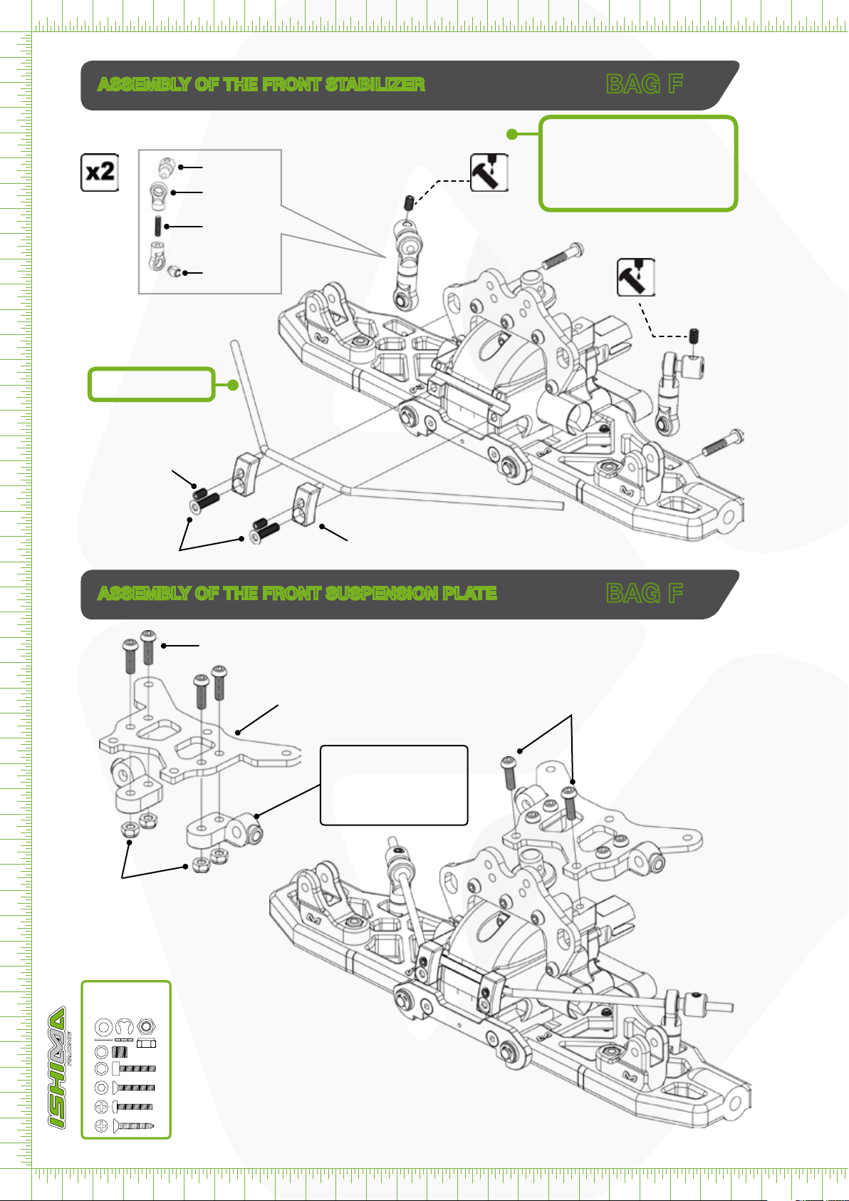
Assembly of the front stabilizer.....................................................................................................................................8
Assembly of the front suspension plate........................................................................................................................8
Assembly of the front suspension arms........................................................................................................................9
Assembly of the steering knuckles ...............................................................................................................................9
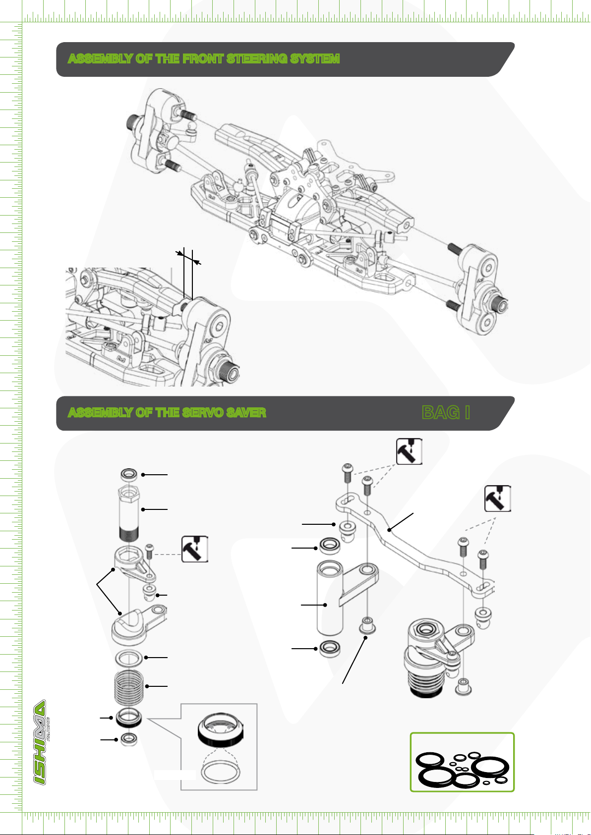
Assembly of the front steering system........................................................................................................................10
Assembly of the Servo Saver......................................................................................................................................10
Installing The Servo Saver ..........................................................................................................................................11
Assembly of the rear suspension................................................................................................................................11
Rear stabilizer .............................................................................................................................................................12
Rear suspension .........................................................................................................................................................12
Rear suspension .........................................................................................................................................................13
Center differential........................................................................................................................................................13
Assembly of the drive trains on the chassis ...............................................................................................................14
Assembly of the chassis stiffeners..............................................................................................................................15
Assembly of the radio plate ........................................................................................................................................16
Assembly of the radio plate ........................................................................................................................................17
The fuel tank ...............................................................................................................................................................18
Assembly of the clutch system ...................................................................................................................................19
The throttle control linkage .........................................................................................................................................20
The FR & RE shock absorbers....................................................................................................................................21
Assembly of the front and Rear shock absorbers .....................................................................................................22
Assembly of the rear wing...........................................................................................................................................23
Throttle linkage & Assembly of the air lter.................................................................................................................24
Fuel Line & tires ..........................................................................................................................................................25
Cut out of the body.....................................................................................................................................................26
Install the stickers .......................................................................................................................................................27
V. Spare & Optional Parts................................................................................................................................................28
VI. Engine .........................................................................................................................................................................30
VII. Carburetor setting.....................................................................................................................................................31
VIII. Starting the engine...................................................................................................................................................31
IX. Transmitter..................................................................................................................................................................32
Handling procedure ....................................................................................................................................................33
Trims & servo reverse..................................................................................................................................................34
XI. Setup sheet.................................................................................................................................................................35
This manual is protected by a copyright and nothing from this edition may be reproduced or used without any prior written authorisation.
Whilst every effort has been made to ensure the accuracy of the information in this manual, errors do creep in and ISHIMA RACING ©
can accept no responsibility for failures, wrong specifications, accuracy of colours, losses or damages caused.
ISHIMA RACING © is not responsible for product changes of this product. The products of dangerous nature included in this manual
are submissive to special handling and storage specifications. Please check with your local authorities for existing legislation.
Version 2008/1

3
This radio controlled model is NOT a toy. Is is recommended that children under the age of 16 are under adult supervision when oper-
ating an RC model.
It is important that you read and respect the instructions of this handbook. You alone are responsible for this model’s safe operation,
therefore you should take enough safety precautions prior to operating this model.
Check all the screws before using, use Nut-Lock if necessary. Check the screws and motor position every tank refill. Only use special
nitro fuel for RC car models.
Never drive the car without the airfilter or with a dirty or defective airfilter.
Length 485mm
Width 305mm
Height 160mm
Weight 3400g
Cut off excess with a wire cutter
I. Safety precautions
II. Rave model dimensions
III. Symbols used in the manual
R/H Screw (Round Head screw)
Set Screw
E-clip
Nylstop nut
METRIC SIZE
F/H Screw (Flat Head screw)
Apply grease
Apply NutLock to the indicated screw or nut
Apply cyano glue (instant glue).
Apply silicon oil (look closely at the bottom of the page
which type of oil is needed!)
Apply special air-filter oil
Assemble left and right sides the same way
Assemble as many times as specified
Bags are only delivered with RAVE R & RAVE RR kit version
Screwbag
RVB-S141
NBR O-Ring set
RVB-S189
E-Clip bag: RVB-S141
BAGS

4
Ball bearing
Ø8x16x5mm
RVB-S144
Diff Case (F/R)
RVB-S034
Ø2 x 9 mm Pin
RVB-S103
Diff. bevel gear 18T
RVB-S070
O-ring
Ø5x1,5mm
RVB-S189
O-ring
Ø5x1,5mm
RVB-S189
Shim ring
Ø5x15x0,1mm
RVB-S089
Shim ring
Ø5x15x0,1mm
RVB-S089
Front & Rear differentials
Front & Rear diff. assembly
Gear differential
Diff. gear 43T
RVB-S068
CNC Racing Diff gear 43T
RVB-S068-R (option)
Ø2 x 9 mm Pin
RVB-S103
Cap Joint
RVB-S055
Diff. Drive Cap Joint
RVB-S055
Diff. bevel gear 18T
RVB-S070
Ball bearing
Ø8x16x5mm
RVB-S144
Differential gasket set
RVB-S091
NBR O-Ring set
RVB-S189
Only use special RC silicone oil
Differential bevel gear shaft
RVB-S075
Shim ring (4)
RVB-S090
NBR O-Ring (optional (4))
Ø5x2,5mm
RVB-S189
F/H M3 x 10mm (4)
! 90% Full
FRONT DIFF. More steering use 2500cps
Standard use 5000cps
Less steering use 10000cps
CENTER DIFF.
Standard use 5000cps
Quick acceleration use 10000cps
REAR DIFF. Standard use 1000cps or grease
REAR DIFF Competition use 5000cps
use 10000cps
FRONT & REAR DIFFERENTIALS
Bevel gear small 10T (4)
RVB-S071
Screwbag
RVB-S141
IV. Assembly of your model
BAG A

5
Ball bearing
Ø8x16x5mm
RVB-S144
Center diff. assembly
Ø2 x 9 mm Pin
RVB-S103
Diff. bevel gear 18T
RVB-S070
O-ring
RVB-S189
Shim ring
RVB-S089
Ball bearing
Ø8x16x5mm
RVB-S144
Differential gasket set
RVB-S091
Only use special RC silicone oil
Differential bevel gear shaft
RVB-S075
Shim ring (4)
RVB-S090
NBR O-Ring (optional) (4)
Ø5x2,5mm
RVB-S189
F/H M3 x 10mm (4)
! 90% Full
Center diff.out drive
RVB-S056
Center diff.
Center diff.out drive
RVB-S056
Steel spur. gear 44T
RVB-S067
FRONT DIFF. More steering use 2500cps
Standard use 5000cps
Less steering use 10000cps
CENTER DIFF.
Standard use 5000cps
Quick acceleration use 10000cps
REAR DIFF. Standard use 1000cps or grease
REAR DIFF Competition use 5000cps
use 10000cps
Diff Case (F/R)
RVB-S034
Ø2 x 9 mm pin
RVB-S103
Diff. bevel gear 18T
RVB-S070
CENTER DIFFERENTIAL
O-ring
RVB-S189
Shim ring
RVB-S089
NBR O-Ring set
RVB-S189
Bevel gear small 10T (4)
RVB-S071
Screwbag
RVB-S141
BAG B

6
ASSEMBLY OF REAR GEARBOX
ASSEMBLY OF FRONT GEARBOX
Front gear box
Rear gear box
Set screw
5x5mm
Set screw
M5x5mm
R/H M3 x 16mm (2)
CNC Rear SusP. Arm Holder 6061
RVB-S084-S
CNC Rear SusP. Arm Holder 7075
RVB-S084-R
Drive Joint
RVB-S057
Drive Joint
RVB-S057
RAVE M1.0S
Pinion Gear13T
RVB-S069
OPTION
CNC Racing Pinion Gear13T
RVB-S069-R (option)
RAVE M1.0S
Pinion Gear13T
RVB-S069
OPTION
CNC Racing Pinion Gear13T
RVB-S069-R (option)
RAVE-M1.0S
Rear Toe In 1° (plastic): RVB-S041-S
RAVE-M1.0R
CNC Rear Toe 7075: RVB-S041-R
Gearbox
RVB-S027
FH/ST M3 x 40mm (2)
FH/ST M3 x 40mm (2)
R/H M3 x 12mm
R/H M3 x 12mm
Gearbox
RVB-S027
Gearbox
RVB-S027
Gearbox
RVB-S027
High Speed
Grease
High Speed
Grease
Ball bearing
Ø8 x 16 x 5 mm
RVB-S144
Ball bearing
Ø8 x 16 x 5 mm
RVB-S144
Ball bearing
Ø8 x 16 x 5 mm
RVB-S144
Ball bearing
Ø8 x 16 x 5 mm
RVB-S144
Shim ring
Ø13x16x0,2mm
RVB-S088
Shim ring
Ø13x16x0,2mm
RVB-S088
Shim ring
Ø13x16x0,2mm
RVB-S088
Shim ring
Ø13x16x0,2mm
RVB-S088
Shim ring
Ø13x16x0,2mm
RVB-S088
Shim ring
Ø13x16x0,2mm
RVB-S088
Screwbag
RVB-S141
R/H M3 x 16mm (2)
RAVE M1.0R
CNC Front Toe-In 7075
RVB-S042-R
RAVE M1.0S
Front Toe In 1° (plastic):
RVB-S041-S
RAVE M1.0S
CNC Front Sus. Arm Holder 6061
RVB-S083-S
RAVE M1.0R
CNC Front Sus. Arm Holder 7075
RVB-S083-R
BAG C
BAG D

7
ASSEMBLY OF FRONT SHOCK TOWER
ASSEMBLY OF FRONT SUSPENSION ARMS
Front Body Mount
RVB-S046
RAVE M1.0S
CNC Front Shock Tower 6061 M1.0S
RVB-S078-S
RAVE M1.0R
CNC Front Shock Tower 7075 M1.0R
RVB-S078-R
R/H M3 x 12mm (5)
R/H M3 x 16mm (2)
R/H M3 x 16mm (2)
E-Clip 3mm
E-Clip 3mm (2)
E-Clip 3mm
Front Sus. Arm-L
RVB-S025
Lower shock support
RVB-S039
Spacer set
RVB-S049
Spacer set
RVB-S049 Set Screw M4 x 8mm
Set Screw M4 x 8mm
Nylstop M3 (2)
Nylstop M3 (2)
Front Lower Susp. Hinge Pin
RVB-S072
Screwbag
RVB-S141
Front Lower Toe In Adjuster
RVB-S049
E-Clip bag: RVB-S141
BAG E
BAG E

8
R/H M3 x 12mm (2)
ASSEMBLY OF THE FRONT STABILIZER
ASSEMBLY OF THE FRONT SUSPENSION PLATE
Front Sway Bar
Stabilizer Ball
RVB-S100
Ball End 6mm
RVB-S051
M3 x 12mm
Ball 6mm
RVB-S102
Front Sway Bar 2.2mm : RVB-S105
(option) 2.3mm : RVB-S106
2.4mm : RVB-S107
Make sure that the sway bar moves
freely!
Set screw
M3 x 3mm
Set screw
M3 x 3mm
Set screw (2)
M3 x 5mm
R/H M3 x 16mm
R/H M3 x 16mm
F/H M3 x 8mm (2)
Sway Bar Plate (*)
RVB-S104
Front Upper Susp. Plate
RVB-S080
RAVE M1.0S
Front Upper Susp. Hinge Pin
Holder Plastic: RVB-S043-S
OPTION
CNC Front Upper Susp. Hinge
Pin Holder 7075: RVB-S043-R
R/H M3 x 8mm (4)
Nylstop M3 (4)
Front Sway Bar Ø2,4mm
RVB-S107
Screwbag
RVB-S141
BAG F
BAG F

9
ASSEMBLY OF THE STEERING KNUCKLES
ASSEMBLY OF THE FRONT SUSPENSION ARMS
Caster clip set
RVB-S199
Set screw
M4 x 4mm
E-clip 3mm (2)
Front Upper Toe In Adjuster set
RVB-S049
Front Upper Hinge Pin
Ø4x49mm
RVB-S073
Front Upper
Susp. Arm RVB-S026
Set screw
M5 x 5mm
Wheel Hub
RVB-S086
Cup Holder Bushing (2)
RVB-S101
Pivot Ball Cup Holder
RVB-S044
Pivot Ball Ø14mm (2)
RVB-S061
Steering Knuckle
RVB-S029
Ball Ø6mm
RVB-S099
Front Universal Drive CVD
RVB-S052
R/H M3 x 10mm
Ball bearing
Ø8 x 16 x 5 mm
RVB-S144
Ball bearing
Ø8 x 16 x 5 mm
RVB-S144
(Upper position)
LEFT
RIGHT
E-Clip bag: RVB-S141
BAG G
BAG H

10
5,3mm
ASSEMBLY OF THE SERVO SAVER
CNC Steering Plate 6061
RVB-S081
R/H M3 x 8mm (2)
R/H M3 x 8mm (2)
Ball Ø6mm (2)
RVB-S099
Ball Ø6mm
RVB-S099
Servo Saver Arm Bushing (2)
RVB-S097
Spring
Spring Bushing
Servo Saver
plast. parts
RVB-S063-P
Servo Saver
plast. parts
RVB-S063-P
Servo Saver Pie
Ball Bearing
Ø6x10x3mm
RVB-S146
ASSEMBLY OF THE FRONT STEERING SYSTEM
Spring Cap
O-ring
Servo saver complete #RVB-S063
Ball Bearing
Ø6x10x3mm
RVB-S146
Ball Bearing
Ø6x10x3mm
RVB-S146
Ball Bearing
Ø6x10x3mm
RVB-S146
NBR O-Ring set
RVB-S189
BAG I

11
ASSEMBLY OF THE REAR SUSPENSION
INSTALLING THE SERVO SAVER
Servo Saver Shaft
RVB-S062
R/H M3 x 8mm
R/H M3 x 12mm (2)
Rear Body Mount
RVB-S046
RAVE M1.0S
CNC Rear Shock Tower 6061
RVB-S079-S
RAVE M1.0R
CNC Rear Shock Tower 7075
RVB -S079-R
R/H M3 x 12mm (3)
R/H M3 x 16mm (2)
R/H M3 x 16mm (2)
Rear Lower Susp. Arm
RVB-S025
Set Screw
M4 x 8mm E-clip 3mm
E-clip 3mm Nylstop M3mm (2)
Nylstop M3mm (2)
E-clip 3mm
Lower Susp. Hinge Pin
RVB-S072
Adjuster
RVB-S049
Lower shock support
RVB-S039
Screwbag
RVB-S141
E-Clip bag: RVB-S141
BAG I
BAG J
RAVE M1.0S
Rear stiffener support plast.
RVB-S184-S
OPTION
CNC Rear Stiffener Support 7075
RVB -S184-R

12
REAR STABILIZER
REAR SUSPENSION
F/H M3 x 8mm
Set Screw M3 x 5mm
Sway Bar holder
RVB-S104
*Sway Bar Rear
Ø2,8mm
RVB-109
Set Screw
M3 x 3mm
Set Screw
M3 x 3mm
R/H M3 x 16mm
R/H M3 x 16mm
Universal Drive CVD
(Option for RAVE S)
RVB-S052 Rear Hub - L
RVB-S030
Wheel Hub Pin
RVB-S115
Wheel Hub
RVB-S086
Set Screw
M5 x 5mm (2)
Ball bearing
Ø8 x 16 x 5 mm
RVB-S144
E-Clip 3mm
E-Clip 3mm
E-Clip 3mm
E-Clip 3mm
Rear hub Hinge Pin
RVB-S074
Plastic Spacer
RVB-S194
Plastic Spacer
RVB-S194
Rear Sway Bar 2.7mm : RVB-S108
(OPTION) 2.8mm : RVB-S109
2.9mm : RVB-S110
Make sure that the sway bar moves freely!
RAVE S use a standard drive shaft RVB-S054
+ 1 Rear wheel axle RVB-S058
Toe-in Adjuster 1°
RVB-S049
Toe-in Adjuster 1°
RVB-S049
Toe-in Adjuster 1°
RVB-S049
Toe-in Adjuster 1°
RVB-S049
Adjuster set 0° - 1° - 1,5°
RVB-S049
Stabilizer Ball
RVB-S100
Ball End 6mm
RVB-S051
M3 x 12mm
Ball 6mm
RVB-S102
BAG L
BAG K

13
REAR SUSPENSION
CENTER DIFFERENTIAL
Turnbuckle
M5 x 45mm
RVB-S066
Rear Upper Arm Ball end
RVB-S050
Rear Upper Arm Ball end
RVB-S050
Ball Ø7mm
RVB-S050
R/H M3 x 23mm
R/H M3 x 23mm
R/H M3 x 8mm
Nylstop M3
Nylstop M3
RAVE M1.0S
Center Diff. Mount set
RVB-S028-S
OPTION
CNC 7075 Center Diff.
Mount set (option)
RVB-S028-R
Brake Disc Holder
RVB-S024
F/H M3 x 8mm (2)
R/H M3 x 16mm (2)
F/H M3 x 8mm (4)
Set Screw M3 x 5mm (2)
Brake Cam Ball bearing (2)
Ø8x5x2,5mm
RVB-S117
Brake Cam lever (2)
RVB-S112
Brake Cam (2)
RVB-S065
CNC Center Diff. Support Plate 6061
RVB-S082
Brake Disc (2)
RVB-S060
R/H M3 x 28mm (4)
Brake Pad Holder
RVB-S059
Brake Pad RVB-S059
14mm
Screwbag
RVB-S141
BAG M
BAG N

14
ASSEMBLY OF THE DRIVE TRAINS ON THE CHASSIS
Left & Right Side Guard
Side Guard (2)
RVB-S032
RAVE M1.0S
CNC Chassis M1.0S: RVB-S077-S
RAVE M1.0R
CNC 7075 Chassis M1.0R: RVB-S077-R
RAVE M1.0RR
CNC 7075 Lightened Chassis M1.0RR: RVB-S077-RR
F/H M3 x 8mm (6)
Front drive train + Center differential + Rear drive train
Front Center Drive Shaft
RVB-S053
Rear Center Drive Shaft
RVB-S053
F/H M4 x 16mm (4)
F/H M4 x 16mm (4)
F/H M4 x 16mm (4)
F/H M4 x 10mm (2)
Front Bumper
RVB-S033
Screwbag
RVB-S141
BAG O

15
ASSEMBLY OF THE CHASSIS STIFFENERS
FR & RE Chassis stiffeners
R/H M3 x 20mm
Nylstop M3
R/H M3 x 12mm (2)
RAVE M1.0S
Chassis stiffener set (plastic)
RVB-S036-S
RAVE M1.0R
CNC Chassis stiffener set 7075
RVB-S036-R
Steering Rod
28mm
Turnbuckle M3x50mm
RVB-S162
Ball End Ø6mm
RVB-S095
Ball End Ø6mm
RVB-S095
Screwbag
RVB-S141
BAG P
BAG Q

16
ASSEMBLY OF THE RADIO PLATE
Steering Servo
17mm
Servo
Turnbuckle M3x30mm
RVB-S157
Ball End Ø6mm
RVB-S098
Ball End Ø6mm
RVB-S098
*Servo Horn (Steering)
RVB-S132
Ball Ø6mm
RVB-S099
* Servo Horn Set RVB-S132
R/H M3 x 16mm (4)
Steering Servo Mount
RVB-S047
Servo holder
RVB-S076
* Adapter for Futaba/JR/KO
R/H M3 x 6mm
Assembly of the radio Plate
Radio Plate Stand
RVB-S176
Transponder support
RVB-S177
CNC Radio Plate 6061
RVB-S094
Radio Plate Post
RVB-S175
R/H M3 x 8mm (4)
R/H M3 x 8mm (6)
Screwbag
RVB-S141
BAG R

17
R/H M3 x 8mm (2)
R/H M3 x 8mm (2)
Receiver Box Set
Switch
Silicone Switch Cover
RVB-S155
Receiver
Antenna Tube
RVB-S172
Switch Cover Plate
RVB-S031
Radio Box
RVB-S031
F/H M3 x 10mm (6)
ASSEMBLY OF THE RADIO PLATE
Screwbag
RVB-S141
BAG S

18
THE FUEL TANK
Fuel Tank with integrated fuel filter
RVB-S093
Fuel Tank Post
RVB-S045
R/H M3 x 12mm (2)
Fuel Guard
Extra Fuel Filter (option)
RVB-S212
R/H M3 x 8mm (2)
R/H M3 x 8mm
Central fuel guard Plate
RVB-S035
Fuel Filter Holder
RVB-S096
F/H M3 x 10mm (2)
Screwbag
RVB-S141
BAG T

19
ASSEMBLY OF THE CLUTCH SYSTEM
Clutch Set Up
Engine Mount
Cap Screw M3 x 12mm (4)
Nylstop M3 (4)
Exhaust Gasket
(Included with the engine)
RAVE M1.0S
CNC Engine Mount
RVB-S085-S
RAVE M1.0R
CNC Racing Engine Mount
RVB-S085-R
Corn Collar
(Included with the engine)
FlyWheel
RVB-S122
Flywheel Nut
RVB-S123
Clutch Spring
RVB-S125
Clutch Bell 13T M1.0S
RVB-S120
OPTION
CNC Racing Clutch Bell 13T RVB-S213
CNC Racing Clutch Bell 14T RVB-S214
CNC Racing Clutch Bell 15T RVB-S215
Clutch Spring 0.9mm RVB-S124
Clutch Spring 1.1mm RVB-S126
Ball Bearing (2)
Ø5x10x4mm
RVB-S145
Clutch Shoes, 3pcs
RVB-S127
Cap Screw
M3 x 10mm
Engine Mount Screw M4 x 8mm
RVB-S128
Screwbag
RVB-S141
BAG U

20
Brake Rod
Throttle Spring
Throttle Rod End
R/H M3x16mm
Brake Rod Support
Set screw
M3 x 3mm
Set screw
M3 x 3mm
Set screw (2)
M3 x 3mm
Servo Horn (Throttle)
RVB-S132
Brake Rod Support
Adapter Futaba/JR/KO
RVB-S132
Stopper
Stopper
R/H M3 x 8mm
Throttle Rod Support
Throttle control linkage set
RVB-S119
Throttle Rod
THE THROTTLE CONTROL LINKAGE
Muffler
Throttle Control Linkage
Muffler M1.0S
RVB-S168
F/H M4x8mm
Muffler Holder Wire
RVB-S185
Set screw
M4x4mm
Set screw
M4x4mm
Muffler Stay
RVB-S193
Manifold
RVB-S166
Exhaust Silicon joint
RVB-S167
Use a piece of Fuel line !
6mm length
Stopper
R/H 3 x 6mm
Screwbag
RVB-S141
BAG V
This manual suits for next models
1
Table of contents