ISOIL ISOMAG ML 145 Operating instructions

OPERATING AND MAINTENANCE MANUAL
ELECTROMAGNETIC FLOWMETER
CONVERTER
MODEL: ML 145
Release number: 145_EN_IS_R0_3.00.0XXX.docx –The characters of file name in
bolt type indicate the software version which the manual refers to; it is visualized at the
instrument start up, or by specific function on DIAGNOSTIC menu.

2
INDEX
INTRODUCTION ........................................................................................................3
SAFETY INFORMATIONS...........................................................................................3
TECHNICAL CHARACTERISTICS ...............................................................................5
ELECTRIC CHARACTERISTICS ......................................................................5
ENVIRONMENTAL USE CONDITIONS ...............................................................5
TORQUES ......................................................................................................5
OVERALL DIMENSIONS AND WEIGHTS...........................................................6
CONVERTER POWER SUPPLY....................................................................................7
MEASUREMENT SETTINGS......................................................................................11
POWER CONSUMPTION ................................................................................12
ELECTRICAL CONNECTIONS ...................................................................................14
SENSOR-CONVERTER CONNECTIONS ............................................................16
OPTIONAL DIGITAL INPUT ...........................................................................17
OPTIONAL DIGITAL OUTPUTS ......................................................................18
ACCESS TO THE CONVERTER KEYPAD....................................................................20
SCREENS DISPLAYED..............................................................................................20
FLOW RATE VISUALIZATION.........................................................................21
ACCESS TO THE CONFIGURATION MENUS ....................................................22
SECURITY ON FUNCTIONS ACCESS ............................................................... 25
ML 145 MAIN MENU FUNCTIONS ...........................................................................26
FUNCTION’S LIST....................................................................................................26
FUNCTIONS DESCRIPTION ...........................................................................29
ALARM MESSAGES, CAUSES AND CORRECTIVE ACTIONS .....................................36
SYSTEM ERROR CODES (start-up/events log).................................................37
APPENDIX 1 DISPLAY ROTATION PROCEDURE.....................................................38
APPENDIX 2 BATTERY SUBSTITUTION ..................................................................39
ISOMAG RETURN MATERIAL FORM........................................................................40
TRANSPORTATION DOCUMENT..............................................................................42
CONFORMITY DECLARATION .................................................................................43
ADDRESSES .............................................................................................................44

3
INTRODUCTION
These operating instructions and description of device functions are provided as part of the
scope of supply. They could be modified without prior notice. The improper use, possible
tampering of the instrument or parts of it and substitutions of any components not original,
renders the warranty automatically void.
The converter is to be used only to be coupled with a sensor to realize a measuring device,
flow meter, that is to be used for measuring the flow of conductive liquids in closed pipes
with conductivity greater than 5µS/cm.
The converter could be coupled directly on the sensor (compact version) or coupled to the
sensor by cable supplied with it (remote version).
The reproduction of this manual and any supplied software is strictly forbidden.
SAFETY INFORMATIONS
Any use other than described in this manual affect the protection provided by the
manufacturer and compromises the safety of persons and the entire measuring system and
is, therefore, not permitted.
The manufacturer is not liable for damaged caused by improper or non-designated use.
1) Transport the measuring device to the measuring point in the original packaging.
Do not remove covers or caps until immediately before installation. In case of
cartons packaging it is possible to place one above the other but no more than
three cartons. In case of wooden packaging do not place one above the other.
2) Disposal of this product or parts of it must be carried out according to the local
public or private waste collection service regulations.
3) The converter must only be installed, connected, commissioned and maintained by
qualified and authorized specialists (e.g. electrical technicians) in full compliance
with the instructions in these Operating Instructions, the applicable norms, legal
regulations and certificates (depending on the application).
converter
sensor

4
4) The specialists must have read and understood these Operating Instructions and
must follow the instructions it contains. The Operating Instructions provide detailed
information about the converter. If you are unclear on anything in these Operating
Instructions, you must call the ISOIL service department.
5) Repairs may only be performed if a genuine spare parts kit is available and this
repair work is expressly permitted.
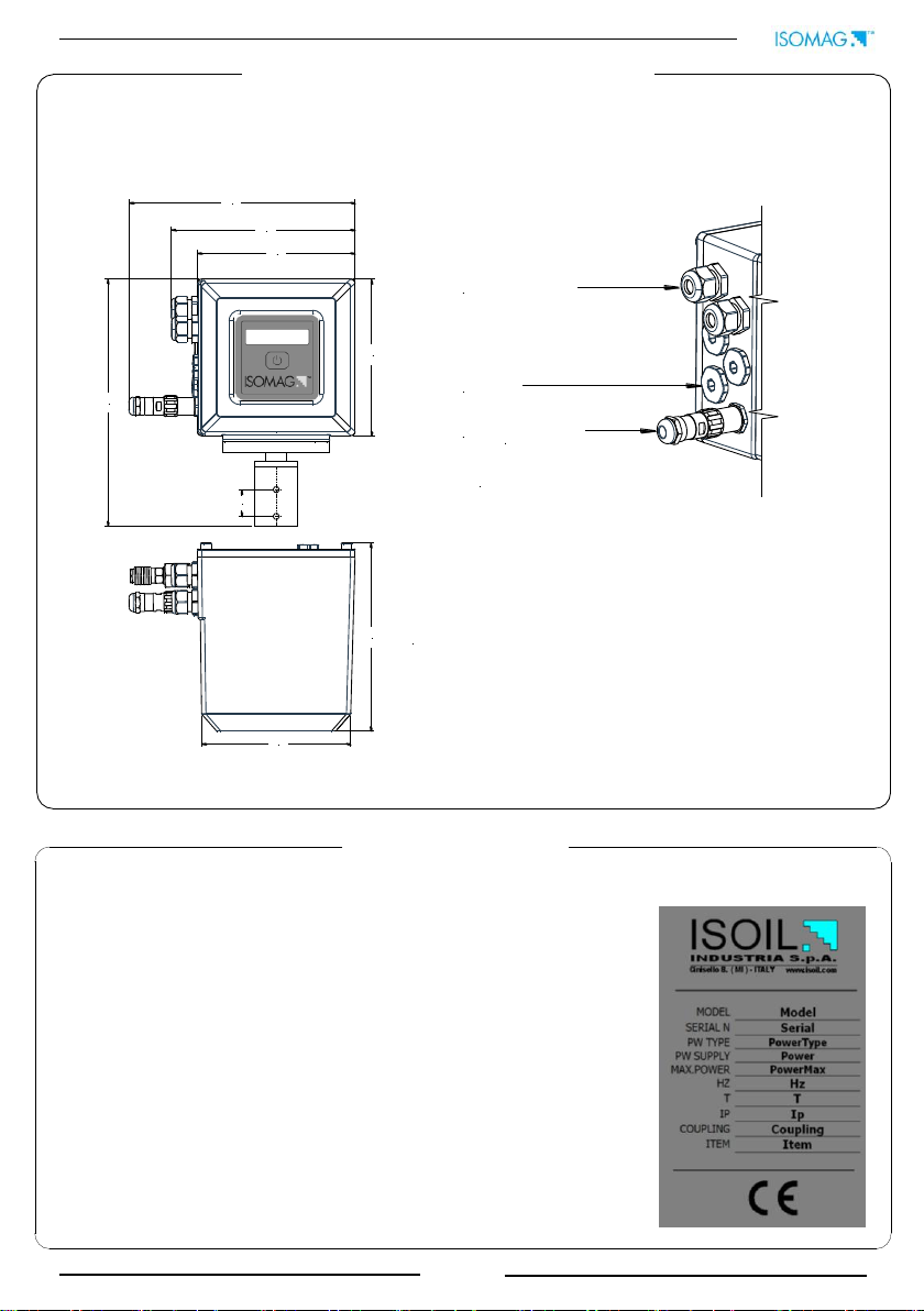
6) The converter should only be installed after have verified technical data provided in
these operating instructions and on the data plate.
7) Specialist must take care during installation and use personal protective equipment
as provided by any related security plan or risk assessment.
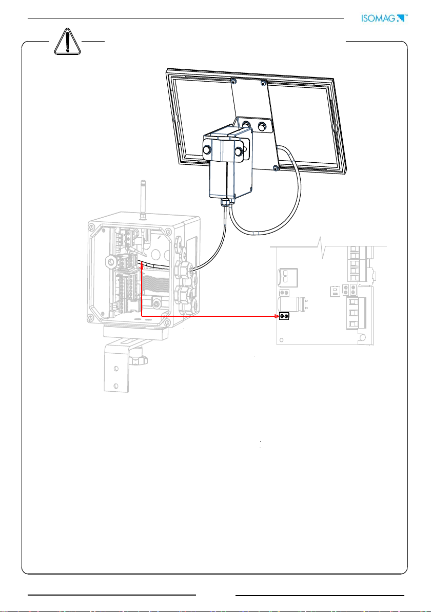
8) Never mount or wire the converter while it is connected to the power supply and
avoid any liquid contact with the instrument’s internal components.
9) Before connecting the power supply check the safety equipment functionality.
10) For the cleaning of the device use only a damp cloth, and for the
maintenance/repairs contact the service center (for details see the last page).
11) To return the product back for service complete and return the meter with form
found in the last pages of these operating instructions.
Before starting up the equipment please verify the following:
Power supply voltage must correspond to that specified on the data plate
Electric connections must be completed as described
Ground (earth) connections must be completed as specified
Verify periodically (every 3-4 months):
The power supply cables integrity, wiring and other connected electrical parts
The converter housing integrity
The suitable tightness of the sealing elements
The front panel integrity (display and keyboard)
The mechanical fixing of the converter to the pipe or wall stand.
SAFETY CONVENTIONS
DANGER
Warning indicates an action or procedure which, if not performed correctly,
can result in injury or a safety hazard. Comply strictly with the instructions
and proceed with care.
WARNING
Caution indicates an action or procedure which, if not performed correctly,
can result in incorrect operation or destruction of the device. Comply
strictly with the instructions.
NOTES
Note indicates an action or procedure which, if not performed correctly,
can have an indirect effect on operation or trigger an unexpected response
on the part of the device.

5
The converter can be installed internally or externally
The direct exposure to the solar rays could damage the liquid crystals display
Altitude: from –200 to 4000 m (from -656 to 13120 feet)
Humidity range: 0-100% (IP 67)
TECHNICAL CHARACTERISTICS
ELECTRIC CHARACTERISTICS
ENVIRONMENTAL USE CONDITIONS
OPERATING TEMPERATURE
TORQUES
Min.*
Max
°C
°F
°C
°F
-20
-4
60
140
Instrument classification: class I, IP 67, overvoltage category II, rated pollution degree 2
Power supply version
Power supply
Power supply
frequency
Max
power
AU
18-30V *
//
1W
LITHIUM BATTERY
NOT RECHARGEABLE
3.6V-19Ah
//
200mW
* Voltage variations must not exceed ±10% of the nominal one.
If the converter is supplied in compact version to the
sensor, consider the operating temperatures more
restrictive, otherwise refer to the respective manuals.
For discontinuous use, a thermostat heat source
installation may be necessary.
CABLE GLAND
IF2 CAP
COVER SCREW
To guarantee the IP housing degree the following
torques are required:
cover screws: 1.5Nm
cable glands: 4Nm (in reference conditions)
IF2 cap: 4Nm
To locate the terminal blocks loosen the 4 screws on
the back cover.

6
175
147
146
139
25
230
171
211
CABLEGLANDPG11
PG11 CAP
QUICK CONNECTOR
LAYOUTAND QUANTITY INACCORDING
TO ORDERCODE
Aluminium housing weight: 3Kg;
Stainless steel housing weight: 3.5kg
Weights refer to the converter without battery (each battery weights 0.1kg),
which can be provided with 6 batteries maximum and without display,
blind configuration.
OVERALL DIMENSIONS AND WEIGHTS
Data plate
On the data plate there is some technical information:
MODEL: Converter Model
SERIAL N: Serial Number of the converter
PW. TYPE: Type of power supply:
oLITHIUM=lithium battery
oAU= Universal power supply
oLITH+AU=lithium battery/es
+ Universal power supply
PW SUPPLY: Main power supply
MAX POWER: Maximum power consumption
Hz: Supply frequency (AC)
T: Operating temperature
IP: Protection grade
COUP: Serial number of sensor coupled
ITEM: free for user

7
Mainvoltage
Solar panelAPL
Batteries
CONVERTER POWER SUPPLY
ML145 can be supplied in three different mode:
by batteries
by mains voltage OPTIONAL
by solar panel (APL) OPTIONAL
Below are shown the Terminal on PCB of the three different power supply

8
B1 CONVERTER BATTERY
OFF
ON
B1
B2
B2 CONVERTER BATTERY
Pic. 1
Pic. 2
B1 CONVERTER BATTERY
B2 CONVERTER BATTERY
-Actual batteries charge status: picture 1.
-In case of dual battery pack (B1&B2) the converter will draw power from battery
pack no. 2 (B2) first, until it is consumed, then will switch automatically on battery
pack no. 1 (B1), giving a BATTERY LOW warning. In this case B1 is considered as a
backup battery. In case of a single battery pack (B1) use B1 slot ALWAYS.
IMPORTANT NOTE: Initially, if the converter has not been powered up for a prolonged
period a ‘BATTERY LOW’ message may appear. This is a temporary and normal response
while the batteries chemical reaction takes place (2-3 hours), the battery will reach the
right value.
POWER SUPPLY BY BATTERIES
To replace the batteries contact the service
Note : Lithium batteries are subject to special transportation regulations according to “Regulation
of Dangeroug Goods, UN3090 and UN 3091”. Special documentation is required to observe there
regulations.
BATTERIES CHARGE STATUS

9
+
-
L
N
Before connecting the power supply, verify that the mains voltage is within the limits
indicated on the data plate.
For the connections use only approved conductors (unsheathed as few as possible),
with fire-proof properties, whose section varies from 0.25mm2to 2.50mm2, based on
distance/power; additionally fix the power supply wires with an additional fastening
system located close to the terminal.
The power supply line must be equipped with an external protection for overload
current (fuse or automatic line breaker).
Provide in close proximity the converter a circuit breaker easy accessible and clearly
identified for the operator; whose symbols must conform to the electrical safety and
local electrical requirements.
Check chemical compatibility of materials used in the connection security systems in
order to minimize electrochemical corrosion.
The ML145 is not intended to be powered on and off repeatedly; the unit will
protect itself against wrongly operation on power supply and will not turn on until all the
internal voltages are ok.
The good way to switch ON and OFF the unit safely, is to use the stand-by
function (main menu 10). In this way the charge is preserved, the data are saved
correctly and the unit will turn on surely when the keyboard is pressed for 10 seconds.
When the converter is connected to the mains power supply, the converter will not
draw power from the batteries; besides the converter will sample at the maximum rate
(continuous sampling).
POWER SUPPLY BY MAINS VOLTAGE (OPTIONAL)

10
Solar Panel Connector
ML145 board (example)
POWER SUPPLY SOLAR PANEL APL (OPTIONAL)
The APL module allows to power up the instruments of Flowiz family through a
photovoltaic module. The system is composed by :
•One photovoltaic panel that converts directly sunlight into electrical energy
•One electronic circuit that use the energy supplied by the module for charging the
battery
•One rechargeable battery already mounted inside the APL’s electronic housing
Once the APL cable is connected to the Flowiz connector (example above), it detect the
presence of module and automatically switch in "CONTINUOUS“ mode, whatever is the
measure profile set; this solution allows accurate measurements (flow/ pressure) even
if they varies continuously. Moreover, if the instrument is equipped with GPRS module,
the APL allows to keep the modem continuously connected to the network, getting a
“almost real time" device.
See APL manual for installation of solar panel and Power Tool software to estimate
the solar panel charge

11
FLOWRATE
PROFILE
CONTINUOS
SAMPLING
SMART
SAMPLING
Max S.R.
5 Sec.
AVERAGE
SAMPLING
3 Sec.
Max S.R.
3 Sec. 3 Sec.
VARIABLE S.R.VARIABLE S.R.
Measures at maximum sample rate
Automatic Sample rate according to flow profile
Sample rate at 3 seconds
TIME
MAX BATTERY
LIFE SAMPLING
15 Sec. 15 Sec. 15 Sec.
S.R.=SAMPLE RATE
Sample rate at 15 seconds
VARIABLE CONSTANT VARIABLE
Max S.R.
The ML 145 converter can be programmed to measure in four different profiles:
The functioning “continuous sampling” is allowed only if the function ENSVE=OFF
(function available only with ISOCON)
MEASUREMENT SETTINGS
Factory pre-setting
= SMART MODE

12
B1: MAINBOARDBATTERIES
(UPTO 3)
MAIN BOARD
IN STANDBY
FLOWRATE
CONTINUOS
SAMPLING
SMART
SAMPLING
AVERAGE
SAMPLING
MAXLIFE
SAMPLING
SAMPLING INTERVALS
INTERFACE ACTIVITIES AND STORAGE DATA
DISPLAYACTIVITIES
B1/B2
B1/B2
B1/B2
B1/B2
B1/B2
B1/B2
B2: MAINBOARDBATTERIES
(UPTO 3)
The batteries consumption depends from the setting of the followings elements: main
board, sampling interval (measure profile), sensor diameter, frequency of data delivery,
amount of data collected, interface activities (display).
Special software to calculate the consumption is available; here below a simple scheme
to evaluate the different “consumption’s rate” of each element.
POWER CONSUMPTION
LOW
CONSUMPTION
MEDIUM
CONSUMPTION
HIGH
CONSUMPTION

13
Power tool is a software
which allows to evaluate
the converter battery life.
The estimation is done
with an easy guided
procedure
Low power consumption: a number of design strategies have been employed to achieve
exceptionally low power consumption. However, the length of time between battery
changes depends on a quality/status of batteries, the frequency of sampling and logging.
POWER TOOL SOFTWARE

14
SOCKET FOR ALTERNATIVE POWERSUPPLY
(SOLARPANELORCOMMERCIALBATTERIES)
TERMINALSOCKETS FOR BATTERIES
TERMINALSOCKETS FOR IF23
SWITCH ON/OFF CONVERTERDIP-SWITCHES
SWITCH ON/OFF INPUT POWERSUPPLY
SOCKET FOR SDMEMORY CARD
ELECTRICAL CONNECTIONS
INTERNAL VIEWS OF THE CONVERTER
The sensor, hardwired inputs and
outputs are connected to the converter
through the terminal blocks.
To locate the terminal blocks remove
the rear protecting cover plate,
removing the 4 fixing screws (5mm
allen key)
When the cover is removed the
terminal blocks are visible. These
terminal are the converter hardwire
connections to the external equipment,
including the sensor.
The following pages give information of
numbering, and the respective
connecting of the sensor cables, and
input/outputs.

15
1 2 3 4 11 12 13 14 15 16
E1 E2 CSH
ELECTRODES
B2
B1
SC
COILS
+ -
INPUT
17 18 19 20 21
OUT2
OUTPUTS
COMMON
+-
4÷20 OUT
-
OUT1
+ +
LEGEND
E1-2: electrode 1-2
B1-2: coil 1-2
C: common
SH: Cable shield, electrically connected to ground and to the housing
TERMINAL BLOCKS M1

16
ALL SENSORS
ALL SENSORS
E1
E2
C+SH
B1
SH
B1
1
2
3
4
11
12
13
E1
E2
C
SH
SH
B1
B2
CABLES MUST BE PLACED INSIDE A METALLIC CONDUIT AND
ELECTRICALLY CONNECTED TO THE CONVERTER HOUSING AND
GROUND (EARTHED)! MAX CABLE LENGTH: 20m
NOTICE: sudden movements of the electrode cable can cause noise on the
measure.
SENSOR-CONVERTER CONNECTIONS
SEPARATE VERSION WITH NORMAL CABLES
SEPARATE VERSION WITH CONNECTORS

17
3.3K
+1K
-
SW
3.3V
+
-
Input
14
15
0-1.5 V
3-40 V
T
RESET
0-1.5 V
3-40 V
BLOCK/ALARM
RESET
OPTIONAL DIGITAL INPUT
INPUTS INSULATION
ELECTRIC WIRING
ON/OFF INPUT FUNCTIONS
Totalizer reset/Board calibration
Alarm/Block total./Wake-up
Necessary conditions to perform the function:
Several functions of the converter can be controlled through the application of an
input voltage (see menu input); the duration of voltage input Tmin must be
500ms as minimum; the scheme below indicate how the input works:
Falling front
Input status
Necessary conditions to perform the function:
T > 0.5 sec.
POS. 5.1-5.4 ENABLED at least one total or
partial, positive or reverse flow totalizer reset
enable
and/or
POS. 5.6 ENABLED
POS. 5.5 ENABLED
and/or
POS. 5.8 ENABLED
Inputs are insulated up to 500V
SW : switch for internal
input power supply, see
above its location

18
(OUT1) (OUT2)
18 17
19 - COMMON
(OUT1 / OUT2)
+
-
24V COMMON
+24V INTERNAL
4-20mA OUT
mA
+
-
I
21
20
OPTIONAL DIGITAL OUTPUTS
OUTPUTS INSULATION
DIGITAL OUTPUT
Technical characteristics
Opto-insulated output (Opto-MOS)
Maximum switching voltage: 40V
/28V~
Maximum switching current: 100mA
Maximum Ron = 70
Maximum switching frequency (load
RL=240, VOUT=24V ): 50Hz
Insulation from other secondary
circuits: 500V
outputs are insulated up to 500V
Opto-insulated output
Maximum load 500Ω
Maximum voltage without load
27V
Protected against persistent over
voltages till 30V
OUTPUT 4÷20mA (ACTIVE)
Technical characteristics

19
DISPLAY FLAGS
FLAGS
FLAGS INTERPRETATION
FLAG
DESCRIPTION
-Max/min alarm activated
C
-Calibration running
S
-Simulation
!
-Alarm signal SEE PAGE 35
At ‘Power on’ of the converter, the user
will see the following display screen. In
the top right hand corner there a range
of symbols. The symbols can be
interpreted from the table below.
Interpretation of the flashing LED can be
made from the LED Interpretation table
at the bottom of this page.
LED WARNING INTERPRETATION
LED INTERPRETATION
The LED of main board flashes every
time the meter perform a measure.
When the LED converter flashes at
approx 1 Hz, this indicates the presence
of an alarm (see page 35)

20
FLOWRATE VALUE / % FULLSCALE
GRAPHIC OF FLOW RATE-TIME
TOTAL AND PARTIAL TOTALIZER
OF DIRECT-INVERSE FLOWRATE
TOTAL AND PARTIAL
NET TOTALIZER
FLOWRATE VALUE PARTIAL
DIRECT INVERSE TOTALIZER
FLOWRATE VALUE
SPEED RATE BAR GRAPH ALARMS STATUS
BATTERYSTATUS
ALTERNATE VIASUALIZATIONS
Note: The user will see the screen displayed (below) at power on.
Use the key as indicated to move between the screens.
SHORT PRESSING (< 1 SECOND):
Change the display of the process data
LONG PRESSING (> 1 SECOND):
Wake up display
NOTE: The maximum digits shown by the totalizer is 999999999 regardless of the number of user
selected decimals (see page 27 Pos 2.3). Beyond this value the totalizers are reset to zero.
ACCESS TO THE CONVERTER KEYPAD
KEYPAD
SCREENS DISPLAYED
Table of contents
Other ISOIL Media Converter manuals
Popular Media Converter manuals by other brands

OT Systems
OT Systems FT110DB Series Installation and operation manual

Cross Technologies
Cross Technologies 2116-116 instruction manual

Shanling
Shanling D600 manual

cabur
cabur CAPIPO3 Installation instruction

Scaltek
Scaltek STK-81H-SCA user manual

Lika
Lika ROTAMAG SMRIL Plus MRI Series Mounting instructions