ISOIL ISOMAG ML 51 Specification sheet

OPERATING AND INSTALLATION MANUAL
CONVERTER
ML 51
ISOMAG
™
THE FRIENDLY MAG METER

2 51_EN_IS_1_3_0X.doc
INTRODUCTION ________________________________________ 3
SYMBOLS USED IN THE MANUAL _________________________ 3
TECHNICAL CHARACTERISTICS __________________________ 4
OVERALL DIMENSION ___________________________________ 5
INTERNAL VIEW OF CONVERTER _________________________ 7
INPUT/OUTPUT _________________________________________ 8
VISUALIZATION PAGE ( WITH IF21 ) ______________________ 10
FLAGS INTERPRETATION AND LED ______________________ 11
FUNCTIONS___________________________________________ 13
ACCESS TO THE CONFIGURATION MENU _________________ 15
FUNCTIONS DESCRIPTION ______________________________ 17
ALARM MESSAGES, CAUSES AND ACTIONS TO BE TAKEN __ 22
ANOMALIES CODES____________________________________ 22
INDEX

3 51_EN_IS_1_3_0X.doc
INTRODUCTION
Symbols Used in the manual
This manual is integral part of the product. Read carefully the instructions contained
since they give important indications for the safe use and maintenance.
Technical information and relative products in this manual could undergo modifications
without any previous notice.
The flow meter must be used for what it has been built for. The improper use, possible
tampering of the instrument or parts of it and substitutions of any not original
components, make the warranty to decay automatically.
The manufacturer is considered responsible only if the instrument it’s used in his original
configuration.
Reproduction of the present manual and of any possible software supplied with the instrument is
strictly forbidden.
ATTENTION
WARNING
PRECAUTIONS
DANGER ELECTRIC SHOC
K

4 51_EN_IS_1_3_0X.doc
TECHNICAL CHARACTERISTICS
OPERATING TEMPERATURE
CONVERTER
Ambient Temp.
Min. Max
°C °F °C °F
-20* -4* 50 140
ELECTRIC CHARACTERISTICS
Classification of the instrument: class I, IP 67, category of installation II
Power supply
versions Power supply
voltage Power supply
frequency current max
Loop 4/20 18÷36 Vdc // 24 mA
4/20 disable 12 Vdc+/-10% CONSUMPTION 12 mA
ENVIRONMENTAL CONDITIONS OF USE
1. The instrument can be installed inside or outside buildings
2. Altitude: from –200 a 6000 m (from -656 to 19685 feet)
3. Humidity range: 0÷100% (IP 65)
Line voltage range: (see table on technical characteristics)
* For discontinuous use, the installation of a heatin
g
resistance is necessar
y

5 51_EN_IS_1_3_0X.doc
OVERALL DIMENSION
127
129
168
124

6 51_EN_IS_1_3_0X.doc
-
+
910
GROUNDING INSTRUCTIONS
For the correct operation of the meter it’s NECESSARY that sensor and liquid are
equipotential, so ALWAYS connect sensor and converter to the ground
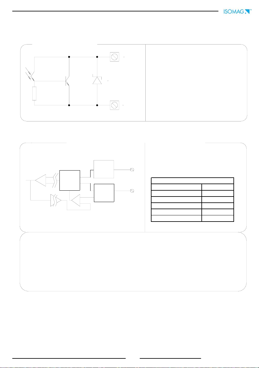
INPUT/OUTPUT ISOLATION
1. Input/output are insulated up to 500V
CONVERTER POWER SUPPLY
Power su
pp
l
y
Before connecting the power supply, verify that
the mains voltage falls between the limits
indicated on the tag plate
ATTENTION: the converters on dc power
supply line are not protected against the
inversions of polarity.
For the wiring use only approved conductors,
with fireproof properties.
In the proximity of the instrument Provide a
circuit breaker that must be easily accessible
from the operator and clearly identified.
NOTE: characteristics of meter’s power supply, see
page 4

7 51_EN_IS_1_3_0X.doc
123456789
10
11121314151617181920
-
E
C
+
SC B2 B1 SC
OUT1
Pow.
OUT
COILS
E1
E2
C
SC
4-20mA
ELECTRODES
+
-
Main Power supply
Pow.
OUT
INTERNAL VIEW OF CONVERTER
12345678910
11 12 13 14 15 16 17 18 19 20
Signalling LED with light:
interpretation at page 11
Socket for IF2
MAIN Power supply
T
ERMINAL BLOCKS OF CONVERTE
R

8 51_EN_IS_1_3_0X.doc
CURRENT
LIMITER
+
-
Galvanic
BARRIER
MAIN
BOARD 9
10
CURRENT
SENSOR
REG.
POWER
SUPPLY
Galvanic
BARRIER
16
17
43V
INPUT/OUTPUT
ON/OFF OUT Opto-insulated output with collector and emitter
terminals floating and freely connectable
Maximum switching voltage: 40 Vdc
Maximum switching current: 10mA
Maximum saturation voltage between collector
and emitter @100mA: 1,2V
Maximum switching frequency 32 Hz
Maximum reverse current bearable on the input
during and accidental polarity reversion (VEC):
100mA
Insulation from other secondary circuits: 500 Vdc
Power supply/Out 4÷20mA
Working voltage : 18 ÷ 36 Vdc
This option allows using the converter like transmitter with technique " 2 wire": the current
4/20 beyond to give the measure also SUPPLY the converter . The MINIMUM value of current,
correspondent to "0" FLOW RATE is 4 mA .
Power Supply R_MAX (ohm)
21.6 (24V-10%) 300
24 400
26.4 (24V+10%) 500
30 680
36 950
MAX LOAD TABLE

9 51_EN_IS_1_3_0X.doc
START UP AND MAINTENANCE OF THE INSTRUMENTS
Before starting up the instrument please verify the following:
Power supply voltage must correspond to that specified in the name plate
Electric connections must be done as described at page 7
Ground connections must be done
Verify periodically:
The integrity of the power supply cables, wiring and other electrical parts
connected
The integrity of the instrument’s housing (this must not have bruises or other
damages that may compromises the hermetical sealing)
The tightening of the sealing elements (cable glands, covers, etc.)
The mechanical fixing of the instrument on the pipe or on the wall stand

10 51_EN_IS_1_3_0X.doc
Scale
Flow rate visualization
*Direct totalizer
*Reverse totalizer
A
lternate page
( 4sec. per pagina )
A
larms
Flow rate visualization
*Partial direct/reverse totalizer
Flow rate visualization
Speed of fluid
VISUALIZATION PAGE ( WITH IF21 )
* The maximum digit shown from the totalizer is 999999999 independently from the number
of selected decimal. Beyond this value the totalise are reset.
FUNZIONE DI “VALUTA” ATTIV
A
Push to change
visualisation
Push to see alarms
page
Push to change
visualisation

11 51_EN_IS_1_3_0X.doc
FACTORY PRESETTINGS
Some functions in the converter are enabled by the access
codes. The information of this manual is related to all the
functions available with L2 level. All the functions available
through higher level are protected and reserved to the
service. Description of the L2 access code
(menu “11 Internal data” pos. 11.1)
with code L2 = 00000 (with this code only) you
disable the request of code L2
NOTE: the availability of the functions is related to the
selected block
*with L2 customised (freely chosen by the user) you
can proceed programming all the functions up to L2
security level, entering its code whenever you enter the
Main menu
*ATTENTION: take note very carefully of the customised
code you have chosen, since there is no way for the user to
retrieve it if it is forgotten
Flags interpretation and LED
LED INTERPRETATION
PERMANENT LIGHT: initialisation
FLASHING at 10/20 Hz : normal function
FLASHING at around 1 second : alarm on
INTERPRETATION FLAGS
FLAG DESCRIPTION
M Alarm max activated
m Alarm min activated
! - Interruption coils circuit
- Segnal error
- Empty pipe
C Calibration running
S Simulation
FLAGS
A
CCESS CODE
The converter is delivered with access code L2:
11111
and with the "Quick start menu" enable. Press the key
to access to the "Quick start menu" from one of the
visualization pages
The “Quick start menu” may be set without entering any
access code (see example 1 on page 14).

12 51_EN_IS_1_3_0X.doc
For converter without keyboard (blind version), the
programming of functions is made up by IF2 serial
device:
SHORT PRESSING (< 1 SECOND):
It increases the numeric figure or the parameter selected by the cursor
It goes to the previous subject on the menu
batch start/stop (when enabled)
LONG PRESSING (> 1 SECOND):
It decreases the numeric figure or the parameter selected by the cursor
It goes to the next subject on the menu
SHORT PRESSING (< 1 SECOND):
It moves the cursor rightwards on the input field
It goes to the following subject of the menu
It changes the display of the process data
LONG PRESSING (> 1 SECOND):
It moves the cursor leftwards on the input field
It goes to the previous subject on the menu
SHORT PRESSING (< 1 SECOND):
It enters/leaves the selected function
It enables the main menu for the instrument configuration
It cancels the selected function under progress
LONG PRESSING (> 1 SECOND):
It leaves the current menu
It enables the totalise reset request (when enabled)
It confirms the selected function
KEYBOARD
BLIND CONVERTERS

13 51_EN_IS_1_3_0X.doc
Functions
(for detail functions with symbol “*”see the manual from page 16)
1.1 Insert ND of sensor ( 0-3000 )
1.2 Calibration data of sensor visualized on sensor’s label
1.3 Type of sensor: Enter the first two characters of the serial number of the sensor
1.4 Position for insertion sensors: 0=1/8DN, 1=1/2DN, 2=7/8DN
1.5 Factory parameter
1.6 Enables the empty pipe detection feature
1.8* Enables the automatic zero calibration system
1.7* Enables the automatic calibration procedure of the empty pipe detection
2.1*Full scale 1 value
2.3* Unit of measure and number of decimal totalizes
2.4* Pulse value
2.5* Duration of the pulse
3.1* Time constant
3.2* Acceleration threshold
3.3* Anomalous si
g
nal pick cut off threshold
3.4 Low flow zero threshold: 0-25% of full scale value
4.1 Maximum value alarm set for direct flow rate
4.2 Maximum value alarm set for reverse flow rate
4.3 Minimum value alarm set for direct flow rate
4.5 Hysteresis threshold set for the minimum and maximum flow rate alarms
4.6 Empty pipe detection threshold. It’s automatically set by the function 1.9
4.4 Minimum value alarm set for reverse flow rate
4.7* Current output value in case of failure
1.9 Reset the precedin
g
function
2.2*Full scale 2 value
3.5 Enable every hour an internal cycle of calibration. The measure it's stopped for 8-15 sec.
3.6 Automatic change of scale

14 51_EN_IS_1_3_0X.doc
6.1* Output functions
8.1 Choice of the language: E= English, I=italian, F= French, S= Spanish
8.6 Quick start menu visualization
8.8 Visualizes the values of the partial totalise in the unit of selected currency
8.9 Choice of the numbers of decimals for the visualization currency value: From 0 to 3
8.10*Value of conversion/currency for direct totalizer
8.11*Value of conversion/currency for reverse totalizer
10.2* Converter autotest
10.3* Flow rate simulation enabling
11.1 Level 2 access code enter
11.3 Load user data saved
11.4 Save user data
11.5 Visualisation of the total operation hours of the converter (function not editable)
11.7 Ks Coefficient
11.2 Load factory data pre-set
7.1 Choice of the communication protocol for the IF2 device
8.2* Total direct (positive) flow totalise reset
8.3* Partial direct (positive) flow totalise reset
8.4* Total reverse (ne
g
ative) flow totalise reset
8.5* Partial reverse (ne
g
ative) flow totalise reset
5.1* Total direct (positive) flow totalise reset enable
5.2* Partial direct (positive) flow totalise reset enable
5.3* Total reverse (negative) flow totalise reset enable
5.4* Partial reverse (negative) flow totalise reset enable
5.6* Autozero calibration external command
5.5 Totalise counting lock command (see page 12)
5.7 Range change external command (see function 3.4)
6.2 Enable 4÷20 output
6.3* Field for 4/20 mA out
7.2 Only for factory use
8.7 Enable the page of net totalizer (difference between direct and reverse. see page 11)
10.1* Enable the calibration of the converter

15 51_EN_IS_1_3_0X.doc
ACCESS TO THE CONFIGURATION MENU
The access to the configuration menu can take place in two different modes:
Through the “Quick start menu” where is possible to access directly to
some of the principal functions
Through the “Main menu” where is possible to access to all function with
access code ≤2
Below are brought some examples relating to the change of the value in the function
“2.1 Fs1”
EXAMPLE: modifying the full scale value from 4dm³/s to 5dm³/s.
from “Quick start menu”
Enter in the “Quick start menu
”
A
ccess to the function “Fs1
”
Push
repeatedly Change the value
Confirm the new value Long push
Main page

16 51_EN_IS_1_3_0X.doc
EXAMPLE: modifying the full scale value from 4dm³/s to 5dm³/s.
from “Main Menu” (quick start menu enable)
Enter in the “Quick start menu
”
A
ccess to the “Main Menu
”
A
ccess to the “Scale” menu
A
ccess to the function “Fs1
”
Change the value Confirm the new value Long push
Long push
Main page
X 5 TIMES
Push
repeatedly
X 3 TIMES

17 51_EN_IS_1_3_0X.doc
MENU 1.SENSOR
(POS. 1) Nominal diameter of sensor [ND= XXXX]
FUNCTIONS DESCRIPTION
(description of the functions with access code< 3)
N.B.: follow are detailed description only some functions of the converter
(see note to page 12)
MENU 1.SENSOR
(POS. 1.7) “Empty pipe” calibration [E.P. CALIBR.]
This function enables the automatic calibration procedure of the empty pipe detection function.
Before performing this function, the sensor has to be completely filled with the liquid. The sensor
has then to be emptied again and then you should press the key : the operation will have to
be confirmed by pressing the key or any other key annul the operation. By this function the
system sets the value of a parameter, which could also be manually changed (see function
“E.P.thr” menu 4-ALARMS).
(POS. 1.8) “Autozero” calibration [AUTOZERO CAL.]
Enables the automatic zero calibration system. To perform the sensor it is absolutely necessary
the sensor is full of liquid and that the liquid is perfectly staying still. Even very small movement
of the liquid may affect the result of this function. When the percentage flow rate value is stable
press the key . Check the percentage flow rate value goes to zero, otherwise repeat the
operation again. When the value is stable at zero, then press .
MENU 2.SCALES
(POS. 2.1-2.2) Full scale n° 1-2 [FS1-2=
dm³/S
X.XXXX]
Full scale value set for range N.1-2. There are four fields to fill in order to set this parameter, from
left to right: 1) volume unit of measure, 2) type of unit, 3) time unit of measure and 4) numeric
value. The selection is made by positioning the cursor on the field to modify. To change the type of
unit of measure (metric, British or American, mass or volume) the cursor has to be positioned on
the symbol “/” (field N. 2). When the nominal diameter is set to zero it is possible to modify only
the numeric field, since the unit of measure stays at m/sec. The following tables show the units of
measure available and the conversion factor by comparison with 1 dm3 and 1 kg. The converter
accepts any kind of combination of units of measure satisfying both the following conditions:
•Numeric field value ≤99999
•1/25 fsmax ≤numeric field value ≤fsmax.
where fsmax is the maximum full scale value corresponding to the sensor, equal to a 10 m/sec liquid
speed. The units of measure are shown as appear on the display. The British and American units
are diversified by using capital and small characters.
Menu visualized on the converter ( from 1 to 11)
Synthetic description of the function
Identification of the function (not visualized on display)
Converter reques
t

18 51_EN_IS_1_3_0X.doc
Available units of mass and volume
When a mass unit of measure is set, the specific gravity function is automatically enabled by the
system. Please, note that the temperature heavily affects the mass measure and therefore with
certain liquids this may cause significant measure errors. The units of measure of time may be
chosen among the following values: s= second, m= minute, h= hour, d= day.
(POS. 2.3) Unit of measure and number of decimal totalizes [UM.tot:dm³X.XXX]
Setting the unit of measure and number of decimals for visualized the totalizes or the volumes to
batch. For set the unit of measure, position the cursor on field of the actual unit of measure; For
set the type of unit, position the cursor on the blank space between the unit of measure and the
numeric value; For set the number of decimal totalizes position the cursor on numeric field and
choose one of the possible combinations: 1000-01.00-001.0-00001.
*(POS.2.4) Pulse value and unit of measure of tot. [PLS=
dm³
X.XXXXX]
Setting of the pulse volume and of the totalizers measure units. There are three fields to fill in to
set this parameter, from left to right: 1) measure unit, 2) unit type and 3) numeric value. The
selection is performed by positioning the cursor on the field to be modified. To change the unit
type (metric, British or American, mass or volume) just position the cursor on the blank space
between the measure unit and the numeric value. When the nominal diameter is set to zero it is
possible to modify only the numeric field since the measure unit stays at meter (m) or feet (ft).
The possible measure units are those above described
(POS.2.5) Pulse duration channel [TPLS=msXXXX.XX]
Setting of the duration of the pulse generated. The possible values are :
16-31-63-125-250-500 mS and 1 or 2 second .
ATTENTION: since the instrument cannot detect which type of device it is connected to, it is up
to the user to verify the set pulse duration is compatible with the external device processing such
pulses. If, for example, an electro-mechanical pulse counter is connected, then two kind of
problems may occur: if the pulse is too long than the coil may burn or, if it is too short, the
counter may not be able to count and eventually even cause the damaging of the output itself.
MENU 3.MEASURE
(POS. 3.1) Time constant [TCONST=s XXXX.X]
This parameter affects the integrating filter making the instrument response quicker or slower,
according to the set value. A higher value corresponds to a more stable but slower measure, a
smaller value the opposite. The most common values are from 1 to 5 seconds. The valid range of
value it’s from 0 (integral filter disabled) to 6000.0 seconds. The following diagram shows the
response of the instrument for a flow rate variation from 0 to 100% within the T time constant
period
(POS. 3.2) Acceleration threshold [SKIP THR=%XXX]
Acceleration threshold set. The acceleration threshold stands for the limit beyond which a flow
rate variation determines an immediate response at the output, without being filtered by the time
constant. This system allows the instrument to have an immediate response in case of big
variations of the flow rate, filtering (and delaying) the response to small variations. The result of
that is a very stable measure, ready to follow the process. The value is set as percentage of the
full scale value from 0 to 125%. If such a value is set to zero any flow rate variation bigger than
0.5% of the full scale value will immediately affect the outputs. The following diagram shows the
in3Cubic inch
gal American gallon
GAL British gallon
ft3Cubic foot
Bbl Standard barrel
BBL Oil barrel
yd3Cubic yard
kgl KAmerican gallon
KGL KBritish gallon
Oz Ounce
Lb Pound
Ton short tons
cm3Cubic centimetre
ml Millilitre
l Litre
dm3Cubic decimetre
dal Decalitre
hl Hectolitre
m3Cubic metre
G Gram
Kg Kilogram
T Ton

19 51_EN_IS_1_3_0X.doc
instrument response in two cases: a flow rate variation from 0 to 10% completely absorbed by
the time constant effect and a variation form 10% to 100% exceeding the acceleration threshold
and then immediately sent to the output. In actual fact there is always a minimum time between
the measure acquisition and the outputs update.
(POS. 3.3) Peak cut off threshold [PEAK THR=% XXX]
Anomalous signal pick cut off threshold set. This parameter allows setting the maximum value of
deviation of the actual measure sample by comparison with the average one. If the new value is
higher than the set limit, than such a value is “cut” to the limit value. This function is used to
make the meter less sensitive to big perturbations on the flow rate measure, as it may happen
when there are solids in suspension in the liquid hitting against the electrodes determining a high
electrical noise. The permitted values of this function range from 0 to 125 % and are referred to
the full scale value. If this parameter is set to zero the peak detection function is disabled and any
new measure ample will be accepted and processed as it is by the converter.
MENU 4.ALARMS
(POS. 4.7) Current output value in case of failure [mA VAL.FAULT =% XXX]
Setting of the value the 0/4...20 mA current output has to be in one of the following cases:
empty pipe; coils interrupted; ADC error
N.B.: To set this parameter to zero corresponds to disable the alarm
MENU 5.INPUTS
(POS. 5.1-5.2-5.3-5.4) Modify/reset totalizer enable [T/P+/-RESET=ON/OFF]
To make the reset of the totalizer from the key board it is necessary enable the functions from
5.1 to 5.4.
From visualisation pages, proceed in the following mode:
pushing the key from visualization page, at the required “RESET TOTALIZ.?” Push the key
and then the key to confirm or any other key to cancel this operation
(POS.5.6)“Autozero”calibration external command enable [CALIBRATION=ON/OFF]
When this function is active, applying a voltage on the on/off input terminals the meter performs
a autozero calibration cycle. ATTENTION: if the voltage pulse is less 1 sec., the meter performs a
calibration cycle for compensate possible thermal drifts. If the voltage pulse is more 1 sec, the
meter performs a zero calibration of measure. This function enables/disables the automatic zero
calibration system. To perform the sensor it is absolutely necessary the sensor is full of liquid and
that the liquid is perfectly staying still. Even very small movement of the liquid may affect the
result of this function, and, consequently, the accuracy of the system.

20 51_EN_IS_1_3_0X.doc
FUNCTION FOR OUTPUT
OFF: DISABLED
IMP+: PULSE ON CHANNEL 1 FOR POSITIVE FLOW RATE
IMP-: PULSE ON CHANNEL 1 FOR NEGATIVE FLOW RATE
IMP: PULSE ON CHANNEL 1 FOR POSITIVE AND NEGATIVE FLOW RATE
SIGN: FLOW DIRECTION OUTPUT (ENERGISED = -)
MAX AL+: MAX DIRECT FLOW RATE OUTPUT(ENERGISED = AL. OFF)
MAX AL-: MAX REVERSE FLOW RATE OUTPUT(ENERGISED = AL. OFF)
MAX AL: MAX DIRECT/REVERSE FLOW RATE OUTPUT(ENERGISED = AL. OFF)
MIN AL+: MIN DIRECT FLOW RATE OUTPUT(ENERGISED = AL. OFF)
MIN AL-: MIN REVERSE FLOW RATE OUTPUT(ENERGISED = AL. OFF)
MIN AL: MIN DIRECT/REVERSE FLOW RATE OUTPUT(ENERGISED = AL. OFF)
MAX+MIN±: MAX AND MIN FLOW RATE ALARM OUTPUT (ENERGISED = AL. OFF)
EMPTY PIPE: EMPTY PIPE ALARM OUTPUT (ENERGISED = FULL PIPE)
OVERFLOW.: OUT OF RANGE ALARM OUTPUT (ENERGISED = FLOW RATE OK)
HW ALARM: CUMULATIVE ALARM OUTPUT interrupt coils, empty pipe, measure error (ENERGISED = NO ALARMS
MENU 6.OUTPUT
(POS. 6.1) Function corresponding to on/off output [OUT1=XXXXXX]
Choice of the function corresponding to digital Output 1. The functions are listed in the table
(POS. 6.3) Choice of the function and the range of current output [OUT.mA1=X÷XX±]
Choice of the function and the range of current output N.1. The current output N.1 is optional and
it is mounted on the main board. There are three fields to modify for this function:
•Scale zero: 4; Full scale: 20 or 22 mA
•Field: += positive, -= negative, ±= both, -0+ = central zero scale
The values corresponding to the scale points are shown in the following chart:
In hardware alarm conditions “HW ALARM” (interrupt coils, empty pipe, measure error) the current
value is programmed by the function “mA VALL. FAULT” (pos. 4.7) and it is expressed as percentage
of a fixed current range, where: 0% = 4 mA e 110% = 22 mA.
CURRENT VALUES IN mA ASSOCIATE TO THE % VALUE OF FULL SCALE
REVERSE FLOW VALUE ZERO DIRECT FLOW VALUE
POSSIBLE FIELD ≤-110% -100% 0% +100%
≥+110%
OutmA = 4 ÷ 20 + 4 4 4 20 20
* OutmA = 4 ÷ 22 + 4 4 4 20 22
OutmA = 4 ÷ 20 - 20 20 4 4 4
OutmA = 4 ÷ 22 - 22 20 4 4 4
OutmA = 4 ÷ 20 ± 20 20 4 20 20
OutmA = 4 ÷ 22 ± 22 20 4 20 22
** OutmA = 4 ÷ 20 –0+ 4 4 12 20 20
OutmA = 4 ÷ 22 –0+ 4 4.8 12.8 20.8 22
* Examlpe 1: uscita 4÷22 + ** Example 2: uscita 4÷20
–
0+
22 mA
20 mA
-110% F.S. -100% F.S. +100% F.S. +110% F.S.
zero
4 mA
I (mA) I (mA)
20 mA
-110% F.S. -100% F.S. +100% F.S. +110% F.S.
zero
12 mA
4 mA
Table of contents
Other ISOIL Media Converter manuals