ISOIL ISOMAG ML 210 Specification sheet

OPERATING AND INSTALLATION MANUAL
CONVERTER
ML 210
Release number: 210_EN_IS_R8_3_9X – The last three digits of file name identify the
software version which the manual refers to; it is visualized at the instrument start up, or by
specific function on DIAGNOSTIC menu.

2
Introduction_________________________________________________3
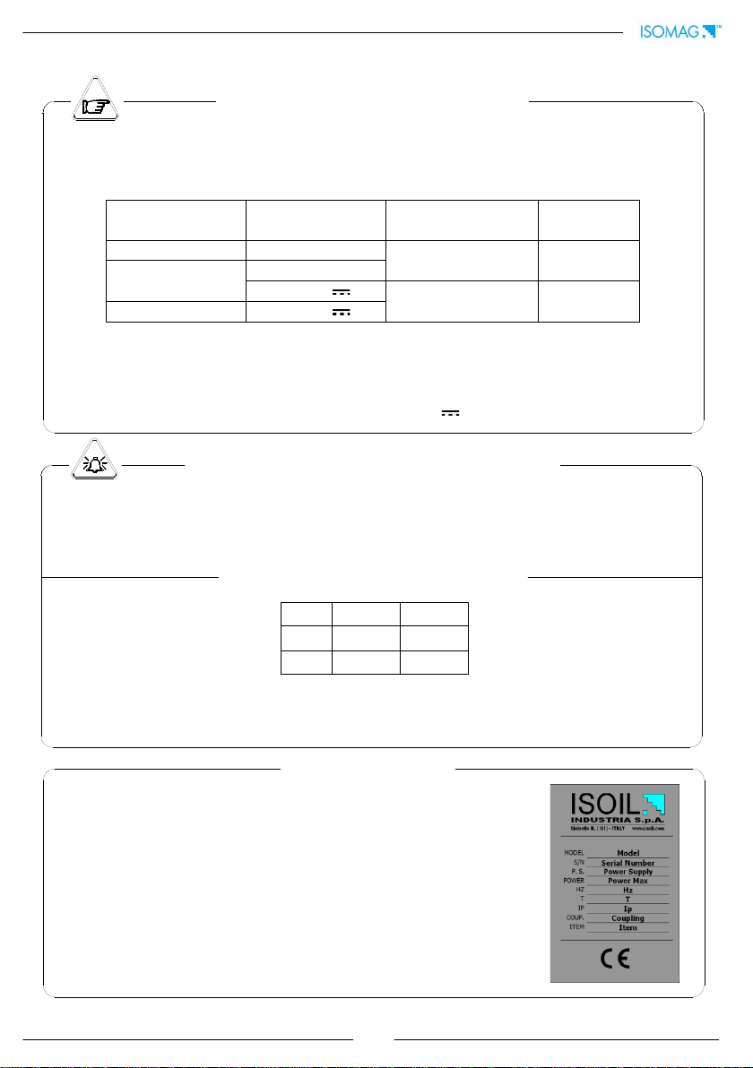
Safety informations ___________________________________________3
Safety conventions___________________________________________________4
Technical characteristics _______________________________________5
Electric characteristics ________________________________________________5
Environmental use conditions __________________________________________5
Ambient temperature_________________________________________________5
Data plate__________________________________________________________5
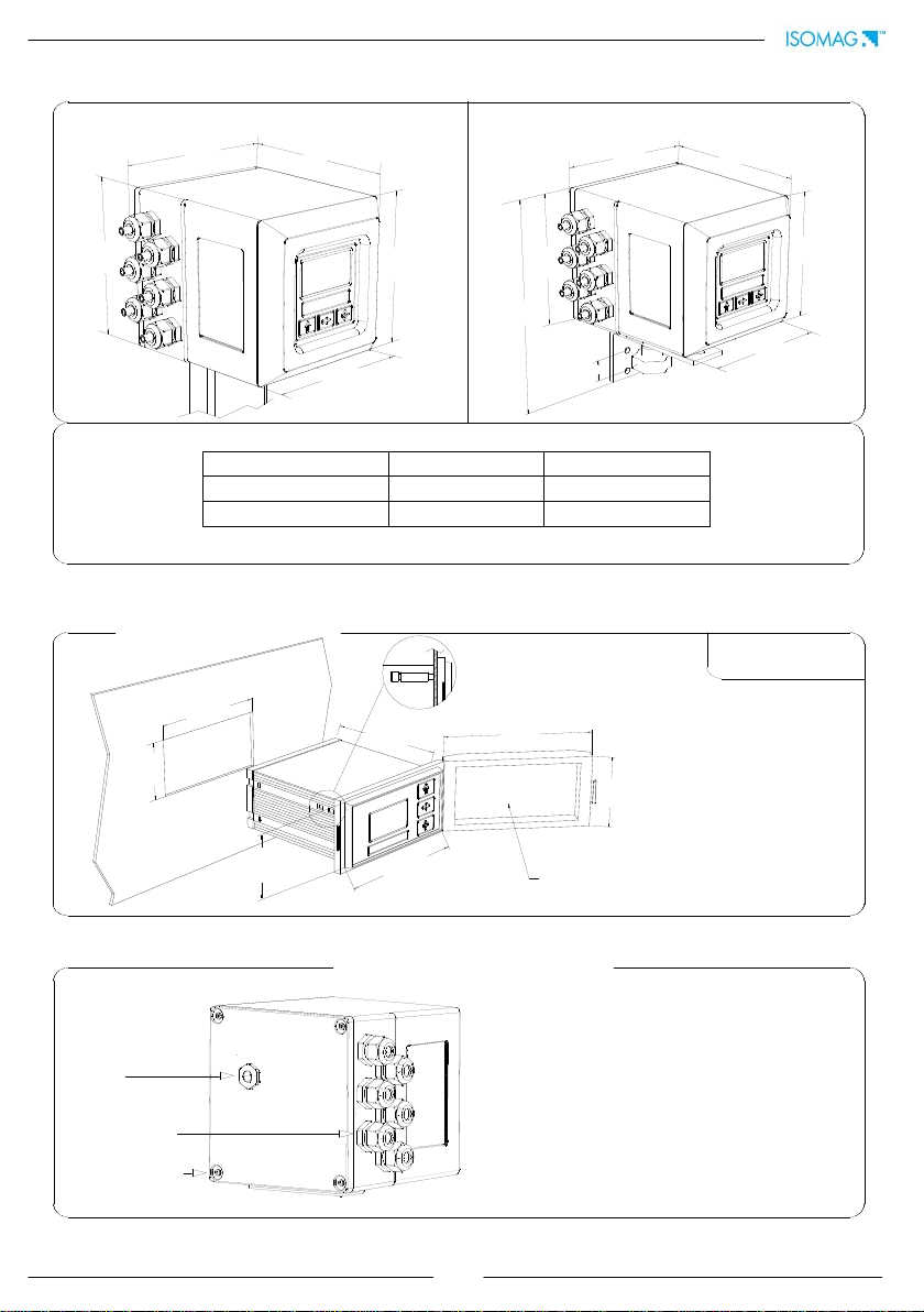
Overall dimensions___________________________________________________6
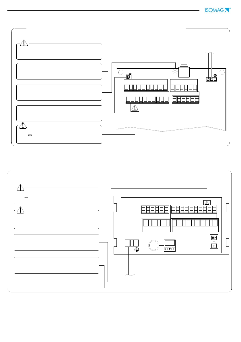
Electrical connections _________________________________________7
Grounding instructions________________________________________________7
Converter power supply_______________________________________________7
Compact/separate version M1 terminal block ______________________________8
Panel version M1 terminal block ________________________________________8
Converter to sensor electrical connections ________________________________9
Optional modules____________________________________________10
Inputs/outputs _____________________________________________12
Digital input _______________________________________________________12
Input operation stage (generic functions)________________________________13
Operation stage on input 1 or 2 (batch function) __________________________ 14
Operation stage on input 1 and 2 (batch function)_________________________ 15
Output wirings _____________________________________________________16
Converter access ____________________________________________17
Flags and led interpretation___________________________________________17
Keyboard _________________________________________________________18
Blind version_______________________________________________________18
Start-up visualization pages___________________________________________19
Flow rate visualization _______________________________________________20
Access codes ______________________________________________________21
Quick start menu ___________________________________________________22
Access to the configuration menu ______________________________________23
Examples _________________________________________________________24
Programming functions _______________________________________26
Functions description________________________________________________29
Batch function confuguration___________________________________38
Alarm messages_____________________________________________40
Appendix: Display rotation procedure ____________________________41
Service: return form for instrument repair or calibration______________45
Conformity declaration________________________________________47
Addresses__________________________________________________48
INDEX

3
converter
sensor
INTRODUCTION
These operating instructions and description of device functions are provided for the scope of
supply. They could be modified without prior notice. The improper use, possible tampering of
the instrument or parts of it and substitutions of any components not original, makes the
warranty to decay automatically.
The converter is to be used only to be coupled with a sensor to realize a measuring device,
flow meter, that is to be used for measuring the flow of conductive liquids in closed pipes with
conductivity greater than 5µS/cm.
The converter could be coupled directly on the sensor (compact version) or coupled to the
sensor by cable supplied with it (remote version).
It is forbidden the reproduction of the present manual and of possible software supplied.
SAFETY INFORMATIONS
Any use other than described here affects the protection provided by the manufacturer and
compromises the safety of people and the entire measuring system and is, therefore, not
permitted.
The manufacturer is not liable for damaged caused by improper or non-designated use.
1) Transport the measuring device to the measuring point in the original packaging. Do
not remove covers or caps until immediately before installation. In case of cartons
package it is possible to place one above the other but no more than three cartons. In
case of wooden package do not place one above the other.
2) Disposal of this product or parts of it must be carried out according to the local public
or private waste collection service.
3) The converter must only be installed, connected and maintained by qualified and
authorized specialists (e.g. electrical technicians) in full compliance with the
instructions in these Operating Instructions, the applicable norms, legal regulations
and certificates (depending on the application).
4) The specialists must have read and understood these Operating Instructions and must
follow the instructions they contain. If you are unclear on anything in these Operating
Instructions, you must call the ISOIL service. The Operating Instructions provide
detailed information on the converter.

4
5) The converter should only be installed after have verified technical data provided in
this operating instructions and on the data plate.
6) Specialists must be carefully during installation and use personal protective equipment
as provided by their security plan about risk assessment.
7) Never mount or wire the converter while it is connected to the power supply and avoid
any liquid contact with the instrument internal components. To connect remove the
terminals from the terminal block.
8) Before connecting the power supply check the safety equipment.
9) Repairs may only be performed if a genuine spare parts kit is available and this repair
work is expressly permitted.
10)For the cleaning of the device use only a damp cloth, and for the maintenance/repairs
contact the service center (for details see the last page).
11)To deliver the converter back to the service workshop use and fill the form in the last
pages of this operating instructions.
Before starting up the equipment please verify the following:
Power supply voltage must correspond to that specified on the data plate
Electric connections must be completed as described
Ground (earth) connections must be completed as specified
Verify periodically (every 3-4 months):
The power supply cables integrity, wiring and other connected electrical parts
The converter housing integrity
The suitable tightness of the sealing elements
The front panel integrity (display and keyboard)
The mechanical fixing of the converter to the pipe or wall stand.
SAFETY CONVENTIONS
DANGER
Warning indicates an action or procedure which, if not performed correctly,
can result in injury or a safety hazard. Comply strictly with the instructions
and proceed with care.
WARNING
Caution indicates an action or procedure which, if not performed correctly, can
result in incorrect operation or destruction of the device. Comply strictly with
the instructions.
NOTES
Note indicates an action or procedure which, if not performed correctly, can
have an indirect effect on operation or trigger an unexpected response on the
part of the device.

5
TECHNICAL CHARACTERISTICS
ELECTRIC CHARACTERISTICS
ENVIRONMENTAL USE CONDITIONS
AMBIENT TEMPERATURE
Data plate
On the data plate there is some technical information:
•MODEL: Converter Model
•S/N: Serial Number of the converter
•P.S.: Power Supply
•POWER: Maximum power consumption
•Hz: Frequency (AC)
•T: Operating temperature
•IP: Protection grade
•COUPLING: Serial number of sensor coupled
•ITEM: free for user
Min. *
Max
°C
-20
60
°F
-4
140
The instrument can be installed inside or outside buildings
Altitude: from –200m to 2000m (from -656 to 5602 feet)
Humidity range: 0-100% (IP 67), 0-90% without condensation (IP54) for panel version
If the converter is supplied in compact version to the sensor, consider the ambient
temperatures more restrictive, otherwise refer to the respective manuals.
*For discontinuous use, a thermostat heat source installation may be necessary.
Instrument classification: class I, IP67 for compact/separate version, IP54 for panel
version (IP65 with optional transparent frontal cover), installation category II, rated
pollution degree 2.
Power supply
versions
Power supply
voltage
Power supply
frequency
Pmax
HV
100-240V~
44-66Hz 25VA
LV
18-45V~
18-45V
// 20W
LLV
10-35V
Voltage changes must not exceed ±10% of the nominal one.
All instrument versions can be equipped with all power supply versions.
Input/output are insulated up to 500V
The output 4-20 mA (optional) and the output 24V are electrically connected.

6
144.0
145.0
67.0
137.0
IP65, TRASPARENT FRONTAL COVER
(OPTIONAL)
72.0
160.0
80.0
OVERALL DIMENSIONS
CABLE GLAND
IF2 CAP
COVER SCREW
138
170
138
146
146
138
170
146
146
230
25
138
SEPARATE VERSION
WEIGHT
Compact
Separate
INOX AISI 304
3kg
3.5kg
Alluminum
2.5kg
3kg
To guarantee the compact/separate
housing’s IP degree the following torques
are required:
cover screws: 1.5Nm
cable glands: 4Nm (in reference
conditions)
IF2 cap: 4Nm
TORQUES
COMPACT VERSION
PANEL VERSION
Weight: 0.5kg

7
L
(+) N
(-)
LN
(+) (-)
M3
M3
ELECTRICAL CONNECTIONS
GROUNDING INSTRUCTIONS
CONVERTER POWER SUPPLY
Compact/separate version
Panel version
ALWAYS ensure that the converter and the sensor are grounded (earthed) correctly. The
grounding of the sensor and converter ensures that the equipment and liquid are
equipotential.
Before connecting the power supply, verify that the mains voltage are within the
limits indicated on data plate.
For the connections use only approved conductors, with fire-proof properties, whose
section varies from 0.25mm2to 2.50mm2, based on distance/power; as well fix the
power supply wires with a additional fastening system located close to the terminal.
The power supply line must be equipped with an external protection for overload
current (fuse or automatic line breaker).
Provide nearness the converter a circuit breaker easily accessible for the operator
and clearly identified; whose symbols must conform to the electrical safety and local
electrical requirements.
Ensure that the component complies with the requirements of the standard for
electrical safety distance.
Check the materials chemical compatibility used in the connection security systems
in order to minimize the electrochemical corrosion.
The sensor, hardwired inputs and outputs are connected to the converter through a
terminal blocks located inside the converter.
To locate the compact/separate version terminal block loosen the 4 screws on the
back cover. When the front cover is lifted, the terminal block is visible. The terminal
block is the hardwire connection of the converter to external equipment, including
the sensor.
The following pages give informations on the terminal block numbering, and the
respective connecting of the sensor cables, and inputs/outputs.

8
20 19 18 17 16 15 14 13 1211
10 9 8 7 6 5 4 3 2 1
32 31 30 29 28 27
26 25 24 23 22 21
M1
M2
M3
M1
M3
1 2 3 4 5 6 7 8 9 10
11 12 13 14 15 16 17 18 19 20
LOCK
323130292827
262524232221
M2
COMPACT/SEPARATE VERSION M1 TERMINAL BLOCK
Dangerous voltage on block 12-13:
- 60V Max
- 250V Max on commutation coils
Dip switch, when the switch is ON, there is NO
more access to the programming functions
Signalling LED: see display flags and led warning
interpretation section
IF2 socket
Power supply
PANEL VERSION M1 TERMINAL BLOCK
Power supply
Dangerous voltage on block positions 12-13:
- 60V Max
- 250V Max on commutation coils
IF2 socket
Dip switch, when the switch is ON, there is NO
more access to the programming functions

9
CONVERTER TO SENSOR ELECTRICAL CONNECTIONS
1
2
3
4
11
12
13
E1
E2
C
SH
SH
B1
B2
1
13
2
3
4
11
12
1 (E1)
10 (preamp.)
9 (preamp.)
8 (preamp.)
7 (preamp.)
6 (preamp.)
2 (E2)
3 (C)
4 (SH)
11 (SH)
12 (B1)
13 (B2)
1 2 3 4 5 6 7 8 9 10
11 12 13 14 15 16 17 18 19 20
E1 E2 CSH + - B A + -
ELECTRODES INPUT RS485 4-20mA
-ECEC+SHB2B1SH OUT2
OUT124VCOILS 24V
ALL SENSORS
ALL SENSORS
WITH PREAMPLIFER
Max cable length: 500m
SENSOR WITH PREAMPLIFIER
Sudden movements of the electrodes
cable, can cause noise on measure.
Max cables length: 20m.
SEPARATE VERSION
TERMINAL BLOCK M1

10
OPTIONAL MODULES
OPTIONAL MODULES(NO RELÈ MODULES)
ME200: 2 programmable on/off outputs +
1 on/off input
ME201: 1 programmable on/off output + 1
high frequency output + 1 on/off input
ME202: 1 4-
20mA output + 2
programmable on/off output + 1 on/off
input
ME203: 1 RS232 port + 2 programmable
on/off outputs + 1 on/off input
ME204: 1 RS232 port + 2 programmable
on/off outputs + 1 4-20mA output + 1
on/off input
ME220, ME221, ME222: data logger, see
the related manual
Protocols: profibus DP, HART and
Modbus, see the related manuals
SH: Cable shield, electrically connected to
ground and to the casing
CTS: Input terminal of the signal “CLEAR TO
SEND” of the RS232 port
RD: Input terminal of the signal “RECEIVE
DATA” RS232 port
TD: Output terminal of the signal “TRASMIT
DATA” of the RS232 port
SG: Terminal “SIGNAL GROUND” common to
all signals of the RS232 port
C: Terminal connected with the on/off output
transistor COLLECTOR
E: Terminal connected with the on/off output
transistor EMITTER
21 22 23 24 25 26
27 28 29 30 31 32
OUT 3
E C CTS RD TD SG
RS 232
- +
INP2 E C
OUT 4 SH
- +
4-20mA
20
(M1)
LEGEND

11
OPTIONAL RELÈ MODULES
ME205: 2 relay outputs with 1 NO
contact + 1 NC contact each, 2A 60V~,
60W/125VA
ME207: 2 relay outputs with 1 NO
contact + 1 NC contact each, 2A 250V~,
60W/125VA
SH: Cable shield, electrically connected to
ground and to the casing
C: Relay – common
NC: Normally closed contact
NO: Normally open contact
LEGEND
26 25 24 23 22 21
OUT 4
CNC NO OUT 3
CNC NO
32 31 30 29 28 27
SH
21 22 23 24 25 26
OUT 3
NO NC COUT 4
NO NC C
14
(M1)
M2
M1
12 3 4 5 6 7 8 9 10
11 12 13 14 15 16 17 18 19 20
LOCK
26
2524232221
M2 for
ME205 and ME207
M2 position on separate/compact version
Teminal block on
compact/separate version
Teminal block on panel
version
NOTE: On panel version
the terminal block M2 is
the same than other
modules.

12
The functions referring to the inputs could be divided in three groups:
1) only assignable functions to the input 1
2) functions that act directly on the inputs independently from the select input
3) only assignable functions to the input 1 and only to the input 2 which interact
between them
For details see the following pages.
Remember that the activation of any functions of batch automatically disable the other.
The list of such functions is suitable in the table of the batch function configuration
section.
INPUTS/OUTPUTS
DIGITAL INPUT
3-40VDC (ON)
0-1.5VDC (OFF)
5 (+)
6 (-)
10k
5
6
20
0
15
+24
10k
External power supply
Internal power supply

13
0-1.5 V
3-40 V
AUTOCALIB. OFF
T
RESET
0-1.5 V
3-40 V
Tmin = 100ms
BLOCK
0-1.5 V
3-40 V
T
0-1.5 V
3-40 V
OPERATION ON INPUT ON/OFF
INPUT OPERATION STAGE (GENERIC FUNCTIONS)
10Hz
20Hz
50Hz
80Hz
150Hz
220ms
110ms
45ms
30ms
15ms
ATTENTION: time T must be ≥
to Tmin
Auto-calibration
Reset totalizers
Block totalizers
Speed rate
Tmin
Block totalizers
Totalizers active
Necessary conditions for enabling the function
Tmin<T<1sec. = autocalibration
T > 1 sec. = Auto zero
POS. 5.7 ENABLED (Autozero calibration external command)
POS. 5.9 DISABLED (batch on input 1)
POS. 5.10 DISABLED (batch functions assign to input 2
(optional)
POS. 5.1 to 5.4 ENABLED (partial positive or reverse
flow totalizers reset enable).
N.B.: This function is even assignable to the input 2
POS. 5.6 ENABLED (totalizers counting lock command)
POS. 12.5 DISABLED (auto-batch)
POS. 12.7 DISABLED (batch consent)
POS. 5.8 ENABLED (range change)
POS. 5.9 DISABLED (batch on input 1)
POS. 5.10 DISABLED (batch functions assign to input
2 (optional))
POS. 6.1-4 DISABLED (end-batch functions assign to
output 2)
Necessary conditions for enabling the function
Range change
Note: THE FUNCTIONS ABOVE ARE ENABLED ONLY ON INPUT 1
Scale 2
Scale 1

14
T
T
OPERATION STAGE ON INPUT 1 OR 2 (BATCH FUNCTION)
Start batch from remote input
Start batch from consent (remote)
Start batch from remote input with auto-
batch enabled
POS. 5.9 or POS. 5.10 ENABLED on batch
POS. 6.1 to 6.4 on end batch
Start batch from remote input with
automatic selection of formula 00/03
N.B.: THE ACTIVATION OF BATCH FUNCTIONS ON INPUT 2
PREVENTS THE ACTIVATION OF BATCH FUNCTIONS ON INPUT 1
Necessary conditions for enabling the function
POS. 5.9 ENABLED or POS. 5.10 on
batch
POS. 6.1 to 6.4 on batch
POS. 12.7 ENABLED (Consent mode)
POS. 5.9 or POS. 5.10 ENABLED on BATCH
POS. 6.1 to 6.4 on END BATCH
POS. 12.5 ENABLED (auto-batch)
POS. 12.7 DISABLED (consent mode)
Necessary conditions for enable the function
T= 100ms ±50ms for select the formula 00
T= 200ms ±50ms for select the formula 01
T= 300ms ±50ms for select the formula 02
T= 400ms ±50ms for select the formula 03
In case of stop batch from remote input the
time of input
POS. 5.9 ENABLED on BATCH or POS. 5.10
POS. 6.1 to 6.4 on END BATCH
POS. 12.6 ENABLED (automatic selection
of formula)
POS. 12.7 DISABLED (consent mode)
POS. 5.10 DISABLED selection function for
the formula 00/01 assigned to input 2 (optional)
Necessary conditions for enabling the function
Start batch from remote input 1 reset p+
enabled on remote input 1
T BETWEEN 1 E 4 = RESET TOTALIZER
T<1 = START E RESET TOTALIZER
Necessary conditions for enabling the function
POS. 5.9 ENABLED (Batch on input 1)
POS. 6.1-4 on BATCH
POS. 5.2 ENABLED (reset P+)
0-1.5V
3-40V
INPUT
OUTPUT
Closing
valve
Opening
valve
BATCH
INPUT
OUTPUT
0-1.5V
3-40V
Opening
valve
Opening
valve
Closing
valve
BATCH
3-40V
0-1.5V
5 Sec.
<5 sec.
INPUT
OUTPUT
Closing valve
quantity to batch
memorized
Opening
valve
Closing
valve
AUTO-BATCH
BATCH
3-40V
0-1.5V
Formula selection
Start
INPUT
OUTPUT
Opening
valve
Closing
valve
BATCH
INPUT
OUTPUT
3-40V
0-1.5V
Start
Opening
valve
Closing
valve
BATCH
Start

15
T
TT
Start batch on remote input 1 stop from output
selection formula 00 o 01 from remote input 2
Block totalizer from remote input 1 start batch from
remote input 2
Block and reset totalize from remote input 1
start batch from remote input 2 consent mode to batch enable
OPERATION STAGE ON INPUT 1 AND 2 (BATCH FUNCTION)
Necessary conditions for enabling the function
POS. 5.9 ENABLED
POS. 6.1 or 6.4 on BATCH
POS. 5.10 ENABLED function of
formula selection 00/01 assigned to input 2
(optional)
The block of the totalizer always
determines the interruption of the
batch. By re-energizing input 2 is
possible to get 2 results:
1) T< 1Sec = restart interrupted
batch
2) T between 1 e 4 Sec = reset
interrupted batch. N.B.: will be
necessary to give a new start
impulse to the input 2 (T< 1Sec)
to begin a new batch
Necessary conditions for enabling the
function
POS. 5.6 ENABLED (Block
totalize)
POS. 6.1 or 6.4 on END BATCH
POS. 5.10 ENABLED (Batch
function for input 2 (optional))
POS. 5.2 ENABLED (P+)
The block of the totalizer (Input 1 signal)
always determines the stopping of the batch.
With the T2 reset function enabled through the
stopping of the input 1 signal the batch
totalizer goes to zero. With the totalizer at zero
a new pulse on Input 2 will restart a new
batch.
Necessary conditions for enabling the function
POS. 5.6 ENABLED (Block totalizer)
POS. 5.10 ENABLED Batch function
assigned to input 2 (optional)
POS. 12.7 ENABLED (consent mode)
POS. 5.2 ENABLED (P+)
3-40V
0-1.5V
Start
Opening
valve
Closing
valve
Opening
valve
Closing
valve
BATCH FORMULA 00
BATCH FORMULA 01
BATCH FORMULA 00
BATCH FORMULA 01
3-40V
INPUT 2
OUTPUT
INPUT 1
3-40V
0-1.5V
Start
Start
Opening
valve
Closing
valve
Opening
valve
Closing
valve
NEW BATCH
RESTART INTERRUPTED
BATCH
OUTPUT
OUTPUT
INPUT 2
INPUT 2
INPUT 1
T<1 Sec.
T between1 and 4 Sec.
3-40V
0-1.5V
Start
RESET
T<1 sec.
Start
Opening
valve
Closing
valve
Opening
valve
Closing
valve
INTERRUPTED BATCH
0-1.5V
3-40 V
BLOCK
0-1.5 V
3-40 V
Start
INPUT 2
Opening
valve
Closing
valve
Opening
valve
Closing
valve
0-1.5V
3-40 V
BLOCK
RESET T2
INPUT 1
OUTPUT
INTERRUPTED BATCH
NEW BATCH
INTERRUPTED BATCH

16
16 (out1)
18 (out2)
17 (out1)
19 (out2)
43V
30
29
43V
24V COMMON
+24V INTERNAL
4-20mA OUT
mA
9 (+)
10 (-)
I
OUTPUT WIRINGS
NOTE: for the inputs and outputs wirings is recommended the use of shielded cables.
Output on/off 1250Hz
Opto-insulated output with collector and emitter
terminals floating and freely connectable
Maximum switching voltage: 40V
Maximum switching current: 100mA
Maximum saturation voltage between collector
and emitter @100mA: 1.2V
Maximum switching frequency (load on the
collector or emitter, RL=470Ω, VOUT=24V ):
1250Hz
Maximum reverse current bearable on the input
during and accidental polarity reversion (VEC):
100mA
Insulation from other secondary circuits: 500V
Opto-insulated output
Maximum load 1000Ω
Maximum voltage without load 27V
Refresh frequency equal to the sample frequency
of the connected sensor
Protected against persistent over voltages up to
30V
Opto-insualted output with collector and emitter terminals
floating and freely connectable. In order to get the
maximum speed performances it is necessary to connect
the emitter to the common terminal of the outputs (0V),
while the load has to be on the collector. This output is
internally connected to the power supply source 24V
available on the terminal block.
Maximum switching voltage: 40V
Maximum switching current: 100mA
Maximum saturation voltage between collector and emitter
100mA, load on the collector and internal power supply:
0.3V
Maximum saturation voltage between collector and emitter
100mA, load on the emitter and internal power supply: 3V
Maximum switching frequency, load on the collector and
internal power supply: (RL=470Ω, VOUT=24V ): 12500Hz
Maximum switching frequency, load on the emitter or
external power supply: (RL=470Ω, VOUT=24V ): 2500Hz
Insulation from the other secondary circuits (except 24V
and 4-20mA outputs): 500V
OUTPUT 1/2 standard - OUTPUT 3/4 with modules
Only with ME 201 module
Output on/off 12500 Hz
The converter detect a loss of load on the 4 to 20mA output; to disable this
function set the value "mA val. fault" to 0 (Pos. 4.6)
4-20mA output

17
M1
M3
1 2 3 4 5 6 7 8 9 10
11 12 13 14 15 16 17 18 19 20
LOCK
CONVERTER ACCESS
FLAGS AND LED INTERPRETATION
FLAGS INTERPRETATION
FLAG
DESCRIPTION
Alarm max/min activated
!
- Interruption coils circuit
- Segnal error
- Empty pipe
C
Calibration running
S
Simulation
Pulse output saturation
(reduce TIME PULSE )
LED
LED INTERPRETATION
PERMANENT LIGHT: initialization
FLASHING LIGHT (1 sec.): normal function
FLASHING LIGHT (<1 sec.): alarm on
The LED signals the real alarm status only if the display visualizes
one of the visualization pages
ATTENTION: The LED is not visible in the panel version of the
converter
FLAGS

18
For the converters without keyboard (blind
version), the programming is made through
ISOCON (cable and software needed).
Being the housing closure dependent by the
installer, the IP degree may be compromised, so
follow the torques mentioned.
KEYBOARD
SHORT PRESSING (< 1 SECOND):
Increases the numeric figure or the parameter selected by the cursor
Returns to the previous subject on the menu
Batch start/stop (when enabled)
LONG PRESSING (> 1 SECOND):
Decreases the numeric figure or the parameter selected by the cursor.
Proceeds to the next subject on the menu
SHORT PRESSING (< 1 SECOND):
Moves/positions the cursor rightward on the input field
Proceeds to the following subject of the menu
Change the display of the process data
LONG PRESSING (> 1 SECOND):
Moves/positions the cursor leftward on the input field
Returns to the previous subject on the menu
SHORT PRESSING (< 1 SECOND):
Enter /leave the selected function
Enables the main menu for the instrument configuration
Cancels the selected function under progress
LONG PRESSING (> 1 SECOND):
Leaves the current menu
Enables the totalizer reset request (when enabled)
Confirms the selected function
BLIND CONFIGURATION

19
*
The direct exposure of the converter to the solar rays, could damage
the liquid crystals display. For the contrast set see pos. 8.3
* The maximum digit shown from the totalizer is 999999999 independently from the number of
selected decimals. Beyond this value the totalise are reset.
Flow rate value
% full scale
Date/time or alarm
Direct/reverse totalizer
Sampling rate
Analogical bar of flow rate variations
Flow direction +/-
See: anomalies codes and
interpretation of flags
C=Calibration
S=Simulation
Flow speed
Scale (1=low); (2=high)
Flow rate value
% full scale
Measure units
Flow direction
Time scale (see Pos. 3.1)
% full scale
Active scale
Flow rate value
Currency value
Total direct totalizer
Partial reverse totalizer
START-UP VISUALIZATION PAGES
Push to change visualisation
CONVERTER VISUALIZATION PAGE WITH CURRENCY FUNCTION ENABLE
The visualization of the pages can be change respect to some functions enabled o disabled (Pos.
8.4÷7÷8 and batch functions)
NOTE

20
The ML 210 allows to show a 5 digit character display for flow rate units; this mean the
maximum flow rate value that can be represented on the display is 99999 (no matter the
positioning of the decimal point). The minimum one is 0.0025.
The representable measure unit depends from sensor flow rate and diameter; the
permitted units are those, set the instrument full scale value, allow to be represented with
a numerical field which the maximum value do not exceed 99999.
Example for DN 300:
-Full scale value: 3m/s
-PERMITTED measure unit (example): l/s (216.00); m3/h (777.60); m3/s (0.2160)
-NOT PERMITTED measure unit (example): l/h (777600)..
FLOW RATE VISUALIZATION
Table of contents
Other ISOIL Media Converter manuals
Popular Media Converter manuals by other brands

CYP
CYP CSO-T2 Operation manual

D-Link
D-Link DMC-300SC - Media Converter - External user manual

Stereoping
Stereoping synth programmer Operation manual

Extron electronics
Extron electronics Scan Converter VSC 500 Specifications

Fujitsu
Fujitsu Airstage UTY-VTGX installation manual

Esser
Esser 784765 Installation instruction