ISOIL ISOMAG ML 252 Specification sheet

OPERATING AND INSTALLATION MANUAL
CONVERTER
ML 252

2
252_EN_I S_1_3_00.doc
qI ntroduction _______________________________________________________________________________________ pag.3
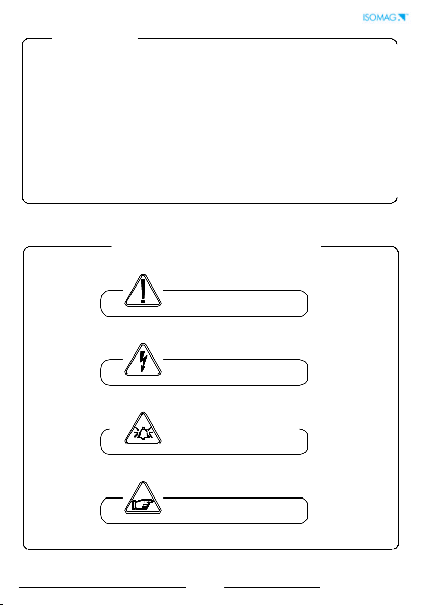
§Symbols Used on the manual ____________________________________________________________________ pag.3
§Overall dimensions _____________________________________________________________________________ pag.4
qTechnical characteristics of converter ______________________________________________________________ pag.5
§Electrical characteristics_________________________________________________________________________ pag.5
§Environmental conditions of use__________________________________________________________________ pag.5
§Operative tem perature __________________________________________________________________________ pag.5
§Measure and consumption ______________________________________________________________________ pag.6
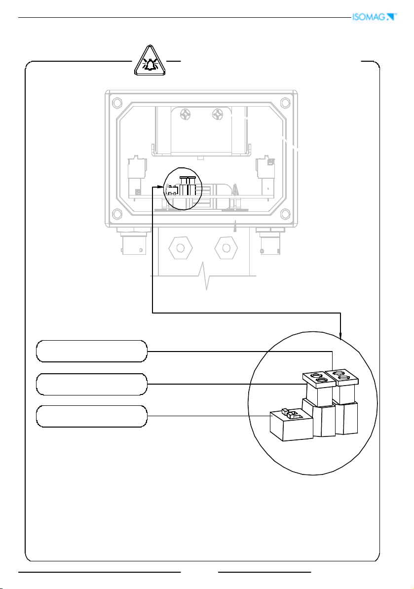
qElectrical connections______________________________________________________________________________ pag.7
§Out put on/ off 50Hz _____________________________________________________________________________ pag.7
qStart up and maintenance of the instruments_______________________________________________________ pag.8
§Device switch on ______________________________________________________________________________ pag.9
§Batteries power supply __________________________________________________________________________ pag.9
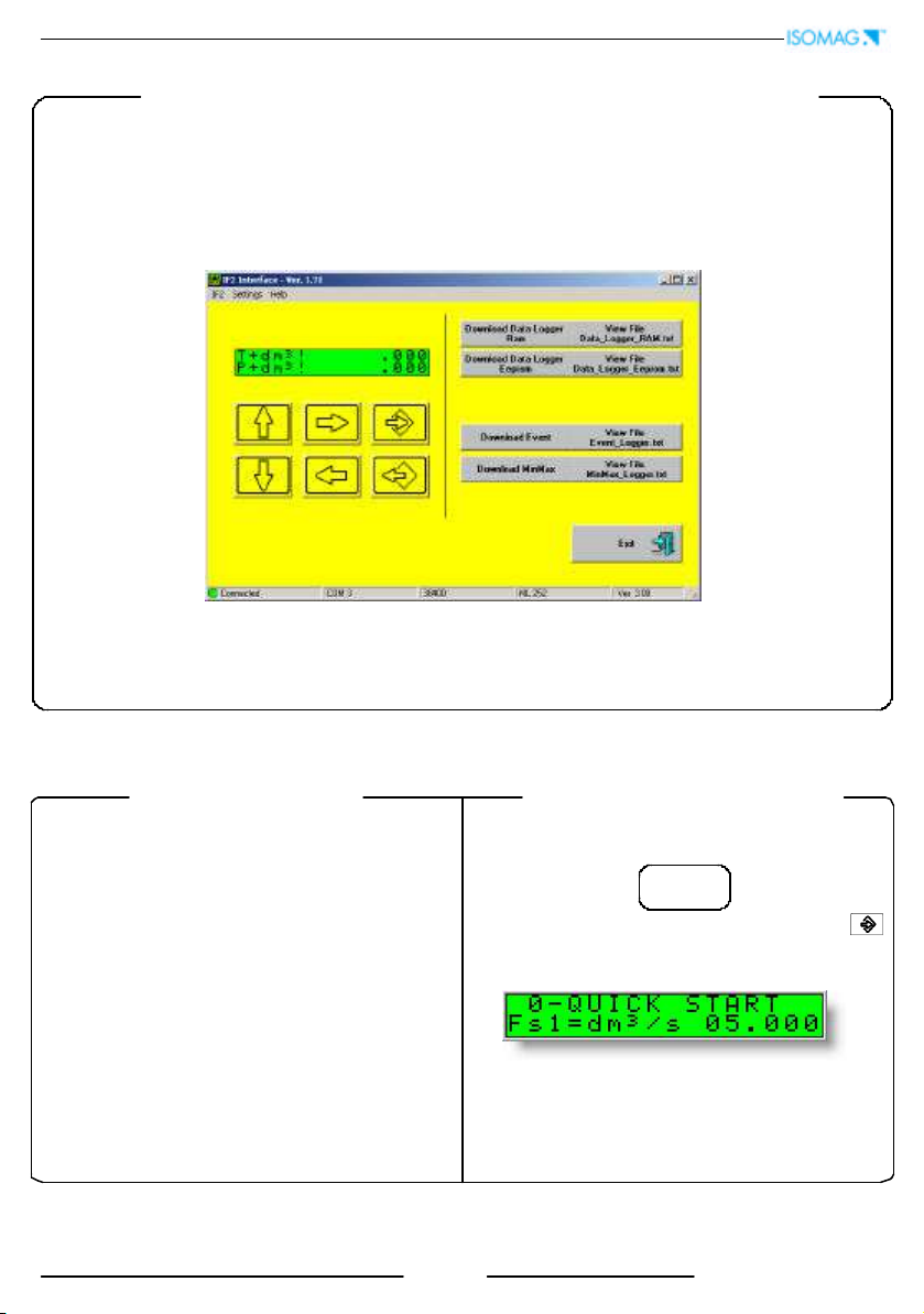
qHow to access at the instrument functions ________________________________________________________ pag.10
§User interface ________________________________________________________________________________ pag.10
§Access codes _________________________________________________________________________________ pag.10
§Converter visualisation pages __________________________________________________________________ pag.11
§Flags interpretation and led _____________________________________________________________________ pag.12
§Converter key board ___________________________________________________________________________ pag.13
§Functions description __________________________________________________________________________ pag.14
§Access to the configuration menu _______________________________________________________________ pag.17
qProgramming functions ___________________________________________________________________________ pag.19
§Functions description __________________________________________________________________________ pag.19
qAlarm messages __________________________________________________________________________________ pag.24
§Causes and action to be taken __________________________________________________________________ pag.24
§Anomalies codes ______________________________________________________________________________ pag.24
APPENDI X 1
Batteries substitution ______________________________________________________________________________________ pag.25
I NDEX

3
252_EN_I S_1_3_00.doc
Symbols Used on the manual
This manual is integral part of the product. Read carefully the instructions contained it
since it contains important indications for a safe of use and maintenance.
Technic
al information and relative products in this manual could undergo modifications
without any previous notice.
The flow meter must be used for what it has been built for. The improper use, possible
tampering of the instrument or parts of it and substitutions
of any not original
components, makes the warranty to decay automatically.
The manufacturer is considered responsible only if the instrument in used in his original
configuration.
The reproduction of the present manual and of possible software supplied
with the instrument it’s strictly forbidden
ATTENTI ON
WARNI NG
PRECAUTI ONS
DANGER ELECTRI C SHOCK
I NTRODUCTI ON

4
252_EN_I S_1_3_00.doc
125
112 97
OVERALL DI MENSI ONS

5
252_EN_I S_1_3_00.doc
TECHNI CAL CHARACTERI STI CS
OPERATI NG TEMPERATURE
CONVERTER
Ambient Temp.
Min. Max
° C ° F ° C
°F
-10*
-14*
50
122
ELECTRI C CHARACTERI STI CS
Classification of the instrument: class I , I P 67, category of installation I I
Power supply
version
Power supply
voltage
Power supply
frequency
Max
pow er
Max
Current
LI TI UM
BATTERY 3,6 V –16,5 A/ h
---
I NPUT/ OUTPUT I SOLATI ON
qI nput/ output are insulated up to 500V
q
Port RS 232 NON is not insulated
ENVI RONMENTAL CONDI TI ONS OF USE
qThe instrument can be installed inside or outside buildings
qAltitude: from –200 a 6000 m (from -656 to 19685 feet)
qHumidity range: 0÷ 100% (IP 67)
qLine voltage range: (see table on technical characteristics)
* For discontinuous use, the installation of heating
resistance is necessary

6
252_EN_I S_1_3_00.doc
The converter can be used in two different modes:
qwith continuous sampling
qwith sampling to preset unit of time.
qCONTI NUOUS SAMPLI NG (pic.1) ( ENERGY SAVI NG OFF)
In this mode the converter make the measure in accordance with the classical diagram of the
flow meter; the consumption of the system, with any diameter of the sensor is 0,05 W ; the
life of battery is about 1 month ( 6 with 6 battery)
The accuracy of the system is definite in those conditions.
qSAMPLI NG TO PRESET UNI T TI ME ( pic. 2 ) ( ENERGY SAVI NG ON )
This mode works sampling the range to intervals of preset time (see MEASURE menu, func.
3.5); it allows a great saving of energy
In this conditions the consumptions are:
Sampling
time (s)
Battery life -n° 1
battery (years)
Battery life –“ N “
batteries (years)
10,7 0,7 * N
21.3 1.3 * N
52.1 2.1 * N
10 2.7 2.7 * N
15 3.0 3.0 * N
> = 30
5
5.0 * N
Whatever the results ,
the maximum time is
limited to 10 years
FLOW RATE
SAMPLE
FREQUENCY
SAMPLE
TI ME
tt
FLOW RATE
SAMPLE
FREQUENCY
PIC 1 PIC 2
ATTENTI ON:
the consumptions on the table are wit
hout optional IF2 cable connected to the
converter. This device accelerate the consumption of the batteries even if the instrument is in standby
mode
. Recommends to disconnect the I F2 cable from the converter after every his uses or
switch off the converter by the dip-sw it ches ( see page 9)
MEASURE/ CONSUMPTI ONS

7
252_EN_I S_1_3_00.doc
ELECTRI CAL CONNECTI ONS
4 poles : OUT ON/ OFF
OUT 1 = Yellow ( terminal C )
OUT 2 = Pink ( terminal D )
50 V
Out common : Cyan ( terminal B )
Technical characteristics
qOpto -insulated output ( Opt o -MOS )
qMaximum switching voltage: 40 Vdc
qMaximum switching current: 100mA
qMaximum Ron = 70 Ohm
qMaximum switching frequency
( loadRL= 240Ω, VOUT= 24Vdc): 32 Hz
qInsulation from other secondary
circuits: 500 Vdc
6 poles
q
A ( ORANGE ) : external power supply
8-35 VDC
qB ( GREEN ) : GROUND
qC ( BROWN ) : RS232 –TX
qD ( VIOLET ) : RS232 –RX
qE ( BLU ) : to IF22USB interface
qF : not connected
I F22

8
252_EN_I S_1_3_00.doc
Before to close the converter verify the following:
qSealing surfaces mast be clean
qTighten the screw in cross mode up to about 12/ 13 Nm
qRepeat the t ightening operations aft er 2/ 3 minutes
1
23
4
I NSTRUMENT START UP AND MAI NTENANCE
Clean surfaces
Before to switch on the instrument verify the following:
qPower supply voltage must correspond to that specified in the name plate
qElectric connections must be done as described at page 8-10
qGround connections must be done
Verify periodically:
qTh
e integrity of the power supply cables, wiring and other electrical parts
connected
qThe integrity of the instrument’s housing (this must not have bruises or other
damages that may compromises the hermetical sealing)
qThe tightening of the sealing elements (cable glands, covers, etc.)
q
The integrity of the front panel (display and keyboard), damages may
compromise the sealing
qThe mechanical fixing of the instrument on the pipe or on the wall stand
Tighten in cross mode

9
252_EN_I S_1_3_00.doc
batteries pack
Batteries Pow er Supply
qBatteries quantity : N° 1 standard ( + N° 1 optional )
SWITCH-ON DEVICE
Switch battery 1
ON/ OFF SWI TCH 1-2
I NS TRUMENT START UP
Switch battery 2

10
252_EN_I S_1_3_00.doc
Some functions in the converter are enabled by the access
codes. The information of this manual is related to all the
functions available with L2 level. All the functions available
through higher level are protected and reserved to the
service.
Description of the L2 access code
(m enu “ 11 I nt ernal dat a” pos. 11.1)
qwith code L2 = 00000
(with this code only) you
disable the request of code L2
NOTE: the availability of the functions is related to the
selected block
q*with L2 customised
(freely chosen by the user) you
can proceed programming all the functions up to L2
security level, entering its code whenever you enter the
Main menu
* ATTENTI ON:
take note very carefully of the customised
code you have chosen, since
there is no way for the user to
retrieve it if it is forgotten
The converter is delivered with access code L2:
11111
and with the "Quick start menu" enable. Press the key
to access to the "Quick start menu" from one of the
visualization pages
The “ Quick start menu” may be set without entering any
access code (see example 1 on page 17).
FACTORY PRESETTI NGS
USER I NTERFACE
ML252 is available only in blind version, therefore
the only way to view and set
the functions of instrument it’s the serial interface IF2 2
ACCESS CODE

11
252_EN_I S_1_3_00.doc
* The maximum number shown from the totalizer is 999999999 independently from the number of
selected decimals. Beyond this value the totalise are reset.
Alarm ON
Flow rate visualization
* Direct Reverse totalizer
Flow rate and direct reverse totalizer visualization
Speed of fluid Alternate pages
Alarm description
Data and time
Push to change visualisation
Push for alrms visualization
Push to change visualisation

12
252_EN_I S_1_3_00.doc
FLAGS I NTERPRETATI ON
FLAG DESCRI PTI ON
MAlarm max activated
mAlarm min activated
!
-Interruption coils circuit
-Segnal error
-Empty pipe
CCalibration running
BPoor power batteries
FLAG AND LED I NTERPRETATI ON
CONVERTER LED I NTERPRETATI ON
Always switch off:not power supply or trouble circuit
Always switch on: firm ware not valid
Continuos quickly flash:normal operation in continuoe sampling mode
Slowly flash ( 2 t ime each second) : empty pipe condition
Alternate quickly flashes: normal operation in energy saving mode
Flash one time each second and sw itch off:switch to stand-by mode
ATTENTI ON: the LED are visible without cover of converter
FLAGS

13
252_EN_I S_1_3_00.doc
SHORT PRESSI NG ( < 1 SECOND) :
It increases the numeric figure or the parameter selected by the cursor
It goes to the previous subject on the menu
batch start/ stop (when enabled)
LONG PRESSI NG ( > 1 SECOND) :
It de
creases the numeric figure or the parameter selected by the cursor
It goes to the next subject on the menu
Visualizes the remaining charge of the batteries
SHORT PRESSI NG ( < 1 SECOND) :
It moves the cursor rightward on the input field
It goes to the following subject of the menu
It change the display of the process data
LONG PRESSI NG ( > 1 SECOND) :
It moves the cursor leftward on the input field
It goes to the previous subject on the menu
SHORT PRESSI NG ( < 1 SECOND) :
I t enter / leaves the selected function
It enables the main menu for the instrument configuration
It cancels the selected function under progress
LONG PRESSI NG ( > 1 SECOND) :
It leaves the current menu
It enables the totalizer reset request (when enabled)
It confirms the selected function
ACCESS TO THE I NSTRUMENT

14
252_EN_I S_1_3_00.doc
1.1 I nsert ND of sensor ( 0-3000 )
1.2 Calibration data of sensor visualized on sensor’s label
1.3 Sensors model
: Enter the first two characters of the serial number of the sensor
1.4 Position f or insertion sensors: 0= 1/ 8DN, 1= 1/ 2DN, 2= 7/ 8DN
1.5
Factory parameter
1.6 Enables the empty pipe detection feature
1.8* Enables the automatic zero calibration sy stem
1.7*
Enables the automatic calibration procedure of the empty pipe detection
2.1* Full scale value set for range N.1
2.3* Unit of measure and number of decimal totalizes
2.4*
Pulse value on channel 1
2.5*
P
ulse value on channel 2
2.7*
Duration of the pulse generated on channel 2
2.6*
Duration of the pulse generated on channel 1
3.1* Time constant
3.2
Low flow zero threshold
: 0
-
25% of full scale value
3.4*
Automatic change of scale
3.5* Energy saving
3.3
Enable
every hour an internal cycle of calibration. The measure it's stopped for 8
-
15 sec.
4.1 Maximum v alue alarm set for direct flow rate
4.2
Maximum value alarm set for
reverse
flow rate
4.3
Minimum value alarm set for
direct
flow rate
4.4
Minimum value alarm set for reverse flow rate
4.5
Hysteresis threshold set for the minimum and maximum flo
w rate alarms
4.6
Empty pipe detection threshold
.
It’s automatically set by the function
1.9
ML252 Functions
(for detail functions with symbol “*”see the manual from page 19)
Attention:
The function in grey colour are visualized on display only with other active
functions or with optional modules
1.9 Reset the preceding function
3.6 I nterval of time among a measure and the other (see page 6)
2.2* Full scale value set for range N.2
3.7 Amplifiers switch-off to save more energy

15
252_EN_I S_1_3_00.doc
6.1* Output 1 functions
6.2*
Output 2 functions
9.3* Date and time set
9.5
Displaying of the data stored in the data logger
9.4* Display dynamic data
9.6
Displaying of the last 64 alarms stored in t
he data logger
9.9 Logged data cancel function
9.7
Visualization function of minimum and maximum peak of flow rate
9.10
Reset all alarm events
9.11
Reset all minimum and maximum peak of flow rate stored
9.2* Interval time for the data logging function: 1, 2, 3, 5, 15, 30, 60 minutes
8.1 Choice of the language: E= English, I = italian, F= French, S= Spanish
8.6
Time for switch off display
(shown with function 3.7 enabled)
8.7
Visualization of “ Quick start menu”
8.8
Enable the page of net totalizer (difference between direct and reverse)
8.9
Visualizes the values of the partial totalise in the unit of selected currency
8.10
Choice of the numbers of decimals for the visualization currency value
: From 0 to
3
8.11*
Value of conversion/ currency for direct t otalizer
8.12*
Value of conversion/ currency for reverse t otalizer
7.1 Choice of the communication protocol for the I F2 device
8.2* Total direct (positive) flow totalise reset from keyboard
8.3* Partial direct (positive) flow totalise reset from keyboard
8.4*
Total reverse (negative) flow totalise reset enable from keyboard
8.5*
Partial reverse (negative) flow totalise reset enable from keyboard
9.1*
Automatic data logger enable
9.8 Logged dynamic data cancel function
7.4 Choice of the communication protocol for the RS232 port
7.2
Address value of converter (
range 0
–
255)
7.3 Speed of the RS232 output (possible choices: 2400, 9600, 19200, 38400 bps)

16
252_EN_I S_1_3_00.doc
10.1* Enable the calibration of the converter
10.2*
Converter auto
-
test
10.3* Flow rate simulation enabling
11.1 Level 2 access code enter
11.4 Load user data saved
11.5
Save user data
11.6
Visualisation of the total operation hours of the converter
(function not editable)
11.7
Ks Coefficient
11.3 Load factory data pre -set
10.4* Stand-by function

17
252_EN_I S_1_3_00.doc
ACCESS TO THE CONFI GURATI ON MENUES
The access to the configuration menu can take place in two different modes:
qThrough the “Quick start menu” where is possible to access directly to
some of the principal functions
qThrough the “Main menu”
where is possible to access to all function with
access code ≤2
Below are brought some examples relating to the change of the value in the function
“2.1 Fs1”
EXAMPLE: modifying the full scale value from 4dm³ / s to 5dm³ / s.
from “Quick start menu”
Enter in the “Quick start menu” Access to the function “Fs1”
Push
repeatedly
Change the value
Confirm the new value Long push
Main page

18
252_EN_I S_1_3_00.doc
EXAMPLE: modifying the full scale value from 4dm³ / s to 5dm³ / s.
from “Main Menu” ( quick start menu enable)
Enter in the “Quick start menu” Access to the “Main Menu”
Access to the “Scale” menu
Access to the function “Fs1”
Change the value Confirm the new value Long push
Long push
Main page
X 5 TIMES
Push
repeatedly
X 3 TIMES

19
252_EN_I S_1_3_00.doc
MENU 1.SENSOR
( POS. 1 ) Nominal diameter of sensor [ ND= XXXX]
FUNCTI ONS DESCRI PTI ON
(description of the functions with access code< 3)
MENU 1.SENSOR
( POS. 1.7 ) “empty pipe” calibrat ion [ E.P. CALI BR.]
This function enables/disables the automatic calibration procedure of the empty pipe detection
function. Before enabling this function, the Empty Pipe test should be enabled first as above
described. Before performing this function, the sensor has to be completely filled with the liquid
so that both the lining and the electrodes are wetted. The sensor has then to be emptied again
and then you should press the key : the operation will have to be confirmed by pressing the
key or cancelled by pressing the key . By this function the system sets the value of a
parameter that could also be manually changed (see function “E.P.thr” menu 4-ALARMS).
( POS. 1.8 ) “Aut ozero” calibration [ AUTOZERO CAL.]
Enables/ disables t he aut omatic zero calibration system. I t is necessary to perform this function at
the first sensor installation or after a long period the sensor has been empty. To perform the
sensor it is absolutely necessary the sensor is full of liquid and that the liquid is perfectly staying
still. Even very small movement of the liquid may affect the result of this function, and,
consequently, the accuracy of the system. Once you are sure the a.m. conditions are fulfilled
press for more than one second the key ; will start one counter for 60 s, after that check if
the zero is correct , otherwise repeat the operation again. Press to go out the function.
MENU 2.SCALES
( POS. 2.1 -2.2) Full scale n° 1-2 [ FS1-2= dm³ / S X.XXXX]
Full scale value set for range N.1-2. There are four fields to fill in order to set this parameter,
from left to right: 1) volume unit of measure, 2) type of unit, 3) time unit of measure and 4)
numeric value. The selection is made by positioning the cursor on the field to modify. To change
the type of unit of measure (metric, British or American, mass or volume) the cursor has to be
positioned on the symbol “/ ” (field N. 2). When the nominal diameter is set to zero it is possible
to modify only the numeric field, since the unit of measure stays at m/sec. The following tables
show the units of measure available and the conversion factor by comparison with 1 dm3 and 1
kg. The converter accepts any kind of combination of units of measure satisfying both the
following conditions:
•Numeric field value ≤99999
•1/25 fsmax
≤numeric field value ≤fsmax
.
where fsmax
is the maximum full scale value corresponding to the sensor, equal to a 10 m/ sec
liquid speed. The units of measure are shown as appear on the display. The British and American
units are diversified by using capital and small characters.
Menu visualized on the converter ( from 1 to 11)
Synthetic description of the function
Identification of the function (not visualized on display)
Converter request

20
252_EN_I S_1_3_00.doc
Available units of mass and volume
When a mass unit of measure is set, the specific gravity function is automatically enabled by the
system. Please, note that the temperature heavily affects the mass measure and therefore with
certain liquids this may cause significant measure errors. The units of measure of time may be
chosen among the following values: s= second, m= minute, h= hour, d= day.
( POS. 2.3 ) Unit of measure and number of decimal totaliz. [ tot. UM.:dm³ X.XXX]
Setting the unit of measure and number of decimals for visualized the totalizer
For set the unit of measure , position the cursor on field of the actual unit of measure; For set
the type of unit, position the cursor on the blank space between the unit of measure and t he
numeric value; For set the number of decimal totaliz . position the cursor on numeric field and
choose one of the possible combinations: 1000-01.00-001.0-00001.
( POS. 2.4 -2.5) Pulse value channel 1 and unit of totaliz . [ I MP1-2= dm³ X.XXXXX]
Setting of the pulse volume corresponding to channel 1-2 and of the totalizers measure units.
There are three fields to fill in to set this parameter, from left to right: 1) measure unit, 2) unit
type and 3) numeric value. The selection is performed by positioning the cursor on the field to be
modified. To change the unit type (metric, British or American, mass or volume) just position the
cursor on the blank space between the measure unit and the numeric value. When the nominal
diameter is set to zero it is possible to modify only the numeric field since the measure unit stays
at meter (m) or feet (ft). The possible measure units are those above described
( POS. 2.6 -2.7) Pulse duration channel 1 [ TPUL1 -2= msXXXX.XX]
Setting of the duration of the pulse generated on channel 1. I ts value is expressed in
milliseconds and has to be between 0.4 and 9999.99.
( POS.2.8 -2.9) Minimum/ maximum value for input 4÷ 20mA [ I . I S= bar ± XXX.XX]
Sett ing the minimum/ maximum value for ext ernal device with 4÷ 20mA out put. There are four
fields to fill in to set this parameter, from left to right: 1) unit of measure, 2) type of unit of
measure and 3) sign, 4) numeric value. The selection is performed positioning the cursor on the
field to modify. To change the type of unit of measure (pressure, temperature or percentage of
f.s) just position the cursor on the blank space between the unit of measure and the numeric
value. This functions is active only with additional module.
MENU 3. -MEASURE
( POS. 3.1 ) Time constant [ T. COST= sXXXX.X]
Time constant set. This parameter affects the integrating filter making the instrument response
quicker or slower, depend to the set value. A higher value corresponds to a more stable but slower
measure, a smaller value the opposit e. The most common values are from 1 to 5 seconds. The
value of this parameter has to be within the range from 0 (integral filter disabled) to 6000.0
seconds. The following diagram shows the response of the instrument for a flow rate variation from
0 to 100% within the T time constant period.
( POS. 3.4) Automatic scale change enable [ AUTORANGE= ON/ OFF]
Enables the automatic change of scale. The meter may have two different working ranges in order
to suit to the variable process conditions. I n order to get the best results out of this function it is
important that range N.2 is bigger than N.1. When the flow rate increases and reaches the 100% of
the full scale 1, then the meter automatically switches to scale 2. When the flow rate decreases
again reaching a value on scale 2 equal to the 90% of full scale N.1, then the active scale is 1
in
3
Cubic inch
Gal American gallon
GAL Brit ish gallo n
ft3Cubic foot
Bbl Standard barrel
BBL Oil barrel
yd3Cubic yard
kgl KAmerican gallon
KGL KBritish gallon
Oz Ounce
Lb Pound
Ton short tons
cm
3
Cubic centimetre
ml Millilitre
lLitre
dm3Cubic decimetre
dal Decalitre
hl Hectolitre
m3Cubic metre
GGram
Kg Kilogram
TTon
Table of contents
Other ISOIL Media Converter manuals
Popular Media Converter manuals by other brands

TDK-Lambda
TDK-Lambda Vega DC Handbook

TEAC PROFESSIONAL
TEAC PROFESSIONAL Tascam LA-80MKII owner's manual

CEL-MAR
CEL-MAR ADA-7021 user manual

Ramsey Electronics
Ramsey Electronics RCA to XLR Converter R2XL1 instruction manual

Baumer
Baumer Hubner HOG 16 M Installation and operating instructions

AUNE
AUNE BU2 user manual