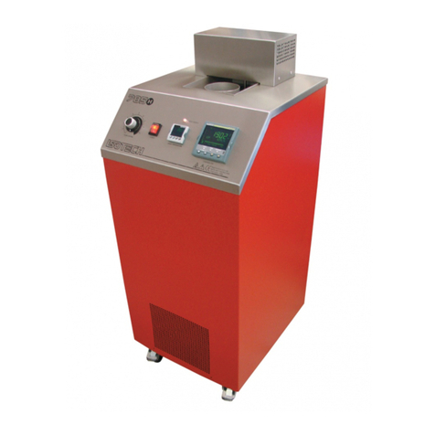
Isotech 989 Operating instructions

Page 1 of 21
Blackbody Source Model 989 (01–09/20)
BLACKBODY SOURCE
MODEL 989
User Maintenance Manual/Handbook
Isothermal Technology Limited, Pine Grove, Southport, PR9 9AG, England
Tel: +44 (0)1704 543830 Fax: +44 (0)1704 544799 Internet: www.isotech.co.uk E-mail: [email protected]
The company is always willing to give technical advice and assistance where appropriate. Equally, because of the programme of
continual development and improvement we reserve the right to amend or alter characteristics and design without prior notice.
This publication is for information only.

Page 2 of 21
Blackbody Source Model 989 (01–09/20)
GUARANTEE
ⓒIsothermal Technology Limited
This instrument has been manufactured to exacting standards and is guaranteed for twelve months against
electrical break-down or mechanical failure caused through defective material or workmanship, provided
the failure is not the result of misuse.
In the event of failure covered by this guarantee, the instrument must be returned, carriage paid, to the
supplier for examination and will be replaced or repaired at our option.
FRAGILE CERAMIC AND/OR GLASS PARTS ARE NOT COVERED BY THIS GUARANTEE
INTERFERENCE WITH OR FAILURE TO PROPERLY MAINTAIN THIS INSTRUMENT MAY INVALIDATE
THIS GUARANTEE
The company is always willing to give technical advice and assistance where appropriate. Equally,
because of the programme of continual development and improvement we reserve the right to amend or
alter characteristics and design without prior notice. This publication is for information only.
Isothermal Technology Limited
Pine Grove, Southport, Merseyside, PR9 9AG, England
Telephone: +44 (0)1704 543830/544611 / Fax: +44 (0)1704 544799
Email: info@isotech.co.uk / Website: www.isotech.co.uk

Page 3 of 21
Blackbody Source Model 989 (01–09/20)
CONTENTS
EMC Information...........................................................................................................................................4
Safety Warnings...........................................................................................................................................5
Environmental Conditions .................................................................................................................................5
Do Not Modify or Disassemble..........................................................................................................................5
Beware of Electrical Considerations .................................................................................................................5
Be Careful Where It Is Used .............................................................................................................................5
Consider the Environment....................................................................................................................................5
Unpacking and Initial Inspection...........................................................................................................................6
Electricity Supply...............................................................................................................................................6
Specification..........................................................................................................................................................7
Operating the Controller .......................................................................................................................................8
Front Panel Layout............................................................................................................................................8
The Temperature Controller..............................................................................................................................8
Altering The Setpoint.........................................................................................................................................8
Advanced Controller Features ..........................................................................................................................8
Setpoint Ramp Rate.................................................................................................................................. 8
Instrument Address.................................................................................................................................... 9
Monitoring The Controller Status ......................................................................................................................9
Units............................................................................................................................................................. 9
Setpoint Lock.............................................................................................................................................. 9
Mounting.............................................................................................................................................................10
Using the External Thermometer Reference Pocket..........................................................................................11
How to install the Optical Extension Tube Accessory ........................................................................................12
Dimensions.........................................................................................................................................................13
Accessories.........................................................................................................................................................14
Using the PC Interface........................................................................................................................................15
Converter Cable..............................................................................................................................................15
Protocol...........................................................................................................................................................15
CAL Notepad ......................................................................................................................................................16
Development...................................................................................................................................................16
Diagnostic Alarms...............................................................................................................................................17
Calibration Procedure.........................................................................................................................................18

Fitting the Thermometer for Calibration ..........................................................................................................18


Page 4 of 21
Blackbody Source Model 989 (01–09/20)
EMC Information
This product meets the requirements of the European Directive on Electromagnetic Compatibility (EMC)
89/336/EEC as amended by EC Directive 92/31/EEC and the European Low Voltage Directive
73/25/EEC, amended by 93/68/EEC. To ensure emission compliance please ensure that any serial
communications connecting leads are fully screened.
The product meets the susceptibility requirements of EN 50082-1, criterion B.
Symbol Identification
Publication
Description
ISO3864
Caution (refer to manual)
IEC 417
Caution, Hot Surface

Page 5 of 21
Blackbody Source Model 989 (01–09/20)
Safety Warnings
Environmental Conditions
•Operating temperature: 5-40°C (41-122°F)
•Relative Humidity: 5-80% - Non-condensing
Do Not Modify or Disassemble
•Do not use the apparatus for jobs other than those for which it was designed, i.e. the calibration of
thermometers
•There are no user serviceable parts inside. Do not dismantle or modify the apparatus. For repair
information contact Isothermal Technology Ltd
•For equipment with fans, the fan should be kept free from dust build up; a soft brush or vacuum
cleaner may be used on the external grill
Beware of Electrical Considerations
•The equipment is for installation category II (transient voltages) and pollution degree II in
accordance with IEC 664 at altitudes to 2000 metres
Be Careful Where It Is Used
•The equipment is not for use in hazardous areas or in an environment close to flammable materials
or gases
•The equipment must be used with adequate space around it for air flow and avoid blocking
ventilation slots
•Ensure free space above the unit to avoid risk of burn or fire
•The equipment should only be used indoors
•Site in a way that allows access to the power switch, and to allow the cable to be disconnected
•Avoid excessive heat, humidity, dust and vibration ensuring it will not be subjected to dripping or
splashing liquids
Consider the Environment
The equipment should be recycled or disposed of in a proper way; following the Waste Electrical
and Electronic Equipment (WEEE) directive

Page 6 of 21
Blackbody Source Model 989 (01–09/20)
Unpacking and Initial Inspection
Our Packing Department uses custom designed packaging to send out your unit, but as accidents can
still happen in transit, you are advised, after unpacking the unit to inspect it for any sign of shipping
damage. Confirm that your delivery is in accordance with the packing note. If you find any damage or
that part of the delivery is missing notify us or our agent, and the carrier immediately. Keep the packing,
if damaged, for possible inspection by an insurance assessor.
Electricity Supply
The power supply operates from any standard AC electrical supply (90-264V RMS at 47-63Hz), so
unless your supply is unusual you can simply connect the power supply to a suitable electrical outlet.
Plug the DC connector from the power supply into the “DC Power” socket on the rear of the unit. Use the
on/off switch on the side panel to turn on the device on and off.

Page 7 of 21
Blackbody Source Model 989 (01–09/20)
Specification
Model
989
Temperature Range
20°C to 50°C
Resolution
± 0.01°C
Target Size
70mm Diameter
(Using Extension Tube)
54mm Diameter
Combined Accuracy / Stability
±0.2°C (0.3°F)
PC Interface
Included, optional cable
Units
°C, °F, K
Block Stability
<±0.01°C
Power
60 Watts
Voltage
12 Vdc (universal supply included)
Dimensions
200mm x 135mm x 170mm
Weight
4kg

Page 8 of 21
Blackbody Source Model 989 (01–09/20)
Operating the Controller
Front Panel Layout
The Temperature Controller
The controller has a dual display, the upper display indicates the nominal block temperature, and the
lower display indicates the desired temperature or setpoint.
Altering The Setpoint
To change the setpoint of the controller simply use the UP and DOWN keys to raise and lower the
setpoint to the required value. The lower display changes to indicate the new setpoint.
Advanced Controller Features
Setpoint Ramp Rate
By default, the Model 989 is configured to heat and cool as quickly as possible. There may be some
calibration applications where it is advantageous to limit the heating or cooling rate.
The source can have its heating rate limited with the Setpoint Ramp Rate feature. This feature is
accessed from the Scroll key. Depress the key until the display shows,
SP.RAT
The upper display will show the current value, and is adjustable from OFF to 999.9. The units are °C/min
and are adjustable via the UP/DOWN keys.
When the SP.RAT is active the lower setpoint display will now automatically update with the current
value, known as the working setpoint. The setpoint can be seen by pressing either the UP and DOWN
key.
The Setpoint ramp rate operates when the bath is heating and cooling.

Page 9 of 21
Blackbody Source Model 989 (01–09/20)
Instrument Address
The controller has a configurable "address" which is used for PC communications. Each instrument has
an address; this allows several instruments to be connected in parallel on the same communications
bus. The default value is 1. This address would only need to be changed if more than one Dry Block is
connected to the same PC port.
To check the Address value, press the scroll key until the lower display indicates,
ADDR
The upper display will show the current value that can be modified with the UP and DOWN keys.
Monitoring The Controller Status
A row of beacons indicates the controller status as follows,
OP1 Heat Output
OP2 Cool Output (only for models which operate below 0°C)
REM This beacon indicates activity on the PC interface
ALM This indicated the setpoint is locked
For models fitted with cooling, the lower display will alternate between the setpoint and the message,
cooling to temperature. It will automatically switch off when the temperature is within 5°C of the setpoint.
Units
Momentary pressing of the Scroll key will show the controller units °C or °F.
Setpoint Lock
The controller has a setpoint lock system to prevent the accidental tampering with setpoint. When
enabled it will disable the UP/DOWN buttons when on the home page.
To enable the setpoint lock press the SCROLL button until L-R is displayed (default setting is NO). Use
the UP/DOWN buttons and change to YES. The setpoint is now locked and can be confirmed by the
flashing red ALM beacon. To disable is a reversal of the above and confirmed by the extinguishing of
the red ALM beacon.

Page 10 of 21
Blackbody Source Model 989 (01–09/20)
Mounting
Model 989 can be mounted on a tripod or suspended from a bracket. There are two easy mount points
with 1/4"-20 UNC thread to accept commonly used tripods and mounting brackets.

Page 11 of 21
Blackbody Source Model 989 (01–09/20)
Using the External Thermometer Reference Pocket
The unit has a reference thermometer pocket that is located in the blackbody block just below the
surface.
If desired a calibrated platinum resistance thermometer can be added for traceability.
The reference thermometer pocket also allows for easy checking and recalibration of the model 989
Blackbody.
1. Remove the dust cover over the thermometer reference hole
2. Locate the pocket in the side of the plate.
3. Insert the thermometer until it reaches the bottom of the pocket (≈58mm)
4. On completion of the calibration remove the thermometer and replace the dust cover

Page 12 of 21
Blackbody Source Model 989 (01–09/20)
How to install the Optical Extension Tube Accessory
Model 989
M4 screws (x4)
Extension tube
To install the extension tube, follow the procedure below:
A. Remove four screws from the front panel of the model 989 using the hex key supplied.
B. Align the extension tube mounting holes to the holes on the model 989.
C. Replace the screws using the hex key supplied. Caution: Do not over-tighten screws

Page 13 of 21
Blackbody Source Model 989 (01–09/20)
Dimensions

Page 14 of 21
Blackbody Source Model 989 (01–09/20)
Accessories
935-16-112 RS422 to RS232 Converter Lead
935-14-82/BW Semi Standard PRT –Temperature Range -50°C to 250°C
989/01 Calibration Kit Comprising of TTI-10 Handheld Thermometer, 935-14-82/TTI Semi Standard
PRT –Temperature Range -50°C to 250°C and 3 Point UKAS System
Calibration, uncertainty 0.02°C (20mK)
988-02-06 Short Tube 40mm
988-02-03 Long Tube 210mm

Page 15 of 21
Blackbody Source Model 989 (01–09/20)
Using the PC Interface
The Model 989 includes an RS422 PC interface, the pin connections are
RS422 Connections
Pin Connection
4 Tx+ A
5 Tx- B
8 Rx+ A
9 Rx- B
1 Common
Converter Cable
There is an optional RS422 to RS232 converter cable from Isotech, part number 935-16-112
Note: The RS 422 standard specifies a maximum lead length of 1200M (4000ft). A true RS422 port will
be required to realise such lead lengths. The Isotech conversion leads are suitable for maximum
combined lead lengths of 10M that is adequate for most applications.
Protocol
The instruments use the "Modbus Protocol"
If required, e.g. for writing custom software the technical details are available from our Document Library
at www.isotech.co.uk

Page 16 of 21
Blackbody Source Model 989 (01–09/20)
CAL Notepad
Cal Notepad can be used can be used to log and display values from the unit and an optional
temperature indicator such as the milliK or TTI-10. The software requires Windows a minimum of 5Mb of
free hard drive space and free serial ports (or an RS232 to USB Converter) for the instruments to be
connected.
Development
Cal Notepad was developed by Isothermal Technology using LabVIEW from National Instruments. The
license details are shown on the download page and in the Cal Notepad manual.
Software Download –Cal Notepad can be downloaded at https://www.isotech.co.uk/downloads

Page 17 of 21
Blackbody Source Model 989 (01–09/20)
Diagnostic Alarms
Diagnostic alarms indicate a possible fault within the controller or connected devices.
Display
shows
What it means
What to do about it
E.Conf
A change made to a parameter takes a
finite time to be entered. If the power to
the controller is turned off before the
change has been entered then this alarm
will occur.
Do not turn the power off to the controller
while ConF is flashing
Enter configuration mode then return to
the required operating mode. It may be
necessary to re-enter the parameter
change since it will not have been entered
in the previous configuration.
E.CaL
Calibration error
Re-instate Factory calibration, refer to
Isotech
E2.Er
EEPROM error
Return to Isotech for repair
EE.Er
Non-vol memory error
Note the error and contact Isotech.
E.Lin
Invalid input type. This refers to custom
linearisation which may not have been
applied correctly or may have been
corrupted.
Go to the INPUT list in configuration level
and set a valid thermocouple or input type
Emod
IO1, OP2, or OP3 has been changed
If this has been field changed by the
installation of a new board, enter config
level, then exit back to operator level.
If the message occurs at any other time
return to factory for repair.
Additional Information;
1. If the input is too high HHHHH will be displayed.
2. If the input is too low LLLLL will be displayed.

Page 18 of 21
Blackbody Source Model 989 (01–09/20)
Calibration Procedure
The model 989 can be recalibrated at Isotech or an authorised partner. It is also possible to recalibrate in
the field. Isotech can provide a calibration kit for suitably experienced calibration engineers.
Fitting the Thermometer for Calibration
1. Remove the dust cover over the thermometer reference hole
2. Locate the pocket in the side of the plate.
3. Insert the thermometer until it reaches the bottom of the pocket (≈58mm)
4. On completion of the calibration remove the thermometer and replace the dust cover
Procedure to calibrate a controller by entering the measured temperature into the instrument. The
instrument then computes the Point and Offset values from the entered temperature.
Caution: This procedure will change the controller calibration and is non reversible.
Set the plate to the required calibration temperature and measure the temperature of the block with a
suitably calibrated thermometer.

Page 19 of 21
Blackbody Source Model 989 (01–09/20)
The Display will then Change to Level 2, and then prompt for the Pass Code
Enter the Pass Code
The controller Pass Code is 2
The instrument will now return to normal operating mode but there are now extra parameters available,
reached by pressing the SCROLL Key

Page 20 of 21
Blackbody Source Model 989 (01–09/20)
To Adjust the First Point press the UP key to select Point 1
The plate can now be set to the next calibration point.
There is a maximum of five points that the plate can be adjusted at.
By default Isotech calibration the 989 at:
Pnt 1 20 °C
Pnt 2 38 °C
Pnt 3 50 °C
Pnt 4 & Pnt 5 are left untouched
Important Notes:
1. The Calibration Points Must be set in ascending temperature order
e.g. 20 °C, 38 °C, 50 °C is good
38 °C, 20 °C, 50 °C is bad
Table of contents
Other Isotech Laboratory Equipment manuals

Isotech
Isotech TWIST User manual

Isotech
Isotech 915 Operating instructions

Isotech
Isotech ORION 796 User manual

Isotech
Isotech B8-30-130 Operating instructions

Isotech
Isotech Saturn 877 Operating instructions

Isotech
Isotech LIBRA 785 Operating instructions

Isotech
Isotech Pegasus R 970 Operating instructions

Isotech
Isotech 17724M Operating instructions