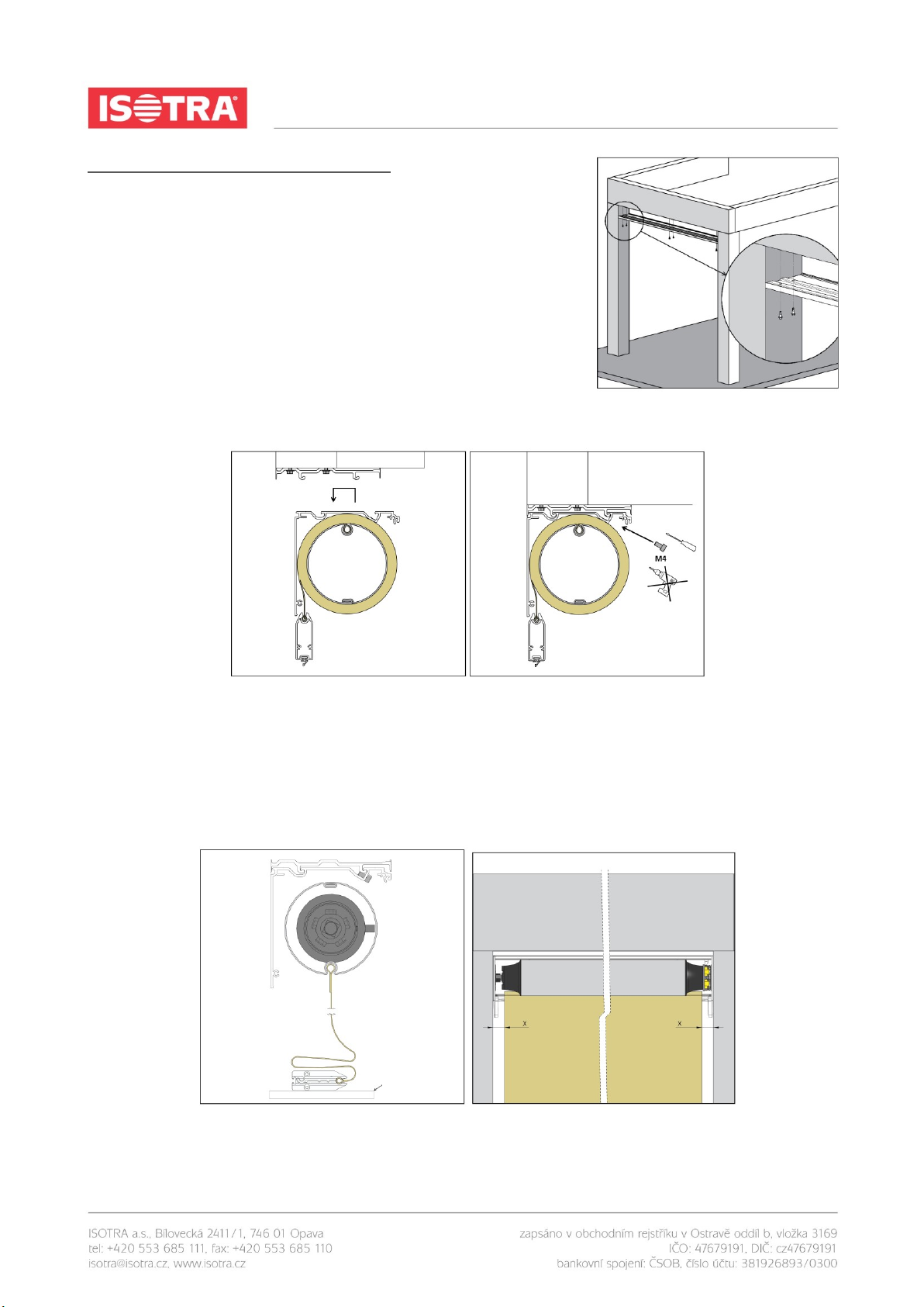
Method 2. Placing the complete assembly of the box and guide rails in or above the window
opening and securing by bolts (used where there is insufficient space for sliding the guide rails on
the side piece pin, for example due to the presence of a window sill or for the self-supporting version
of the screen roller shutter).
Step 1: Drilling the holes for the wall/ceiling holders
1. Place the wall/ceiling holders to the assembly
surface. Use the upper holes for ceiling mounting,
and the rear holes for wall mounting.
2. The box must be perfectly horizontal, and
therefore make sure whether the wall/ceiling
holders are properly aligned. To do this, use a
tube spirit level and a plumb line, or another
suitable tool.
3. The wall/ceiling holders must be installed 40–100
mm from the box sides. Any additional holders are
to be installed evenly distributed along the box
width and they are intended to prevent arching of
wider boxes.
For the self-supporting version, skip Step 1 and continue
to Step 2.
Step 2: Drilling the holes for the guide rails
Guide rails A839, A829:
1. Indicate holes to be drilled to the wall or another
assembly surface. Use predrilled guide rails to do
this.
2. A indicates holes for attaching the guide rails (see
Fig. below).
3. B indicates holes for the holders (see Fig. below).
Attach the holders to the assembly surface.