2. Guideline for connection and use of photometer
2. 1. Field of use
Photometer is designed for measuring and regulating illumination in traffic areas. It
provides adequate ilumination at any time of the day and any light conditions. Its basic
application is to regulate the illumination of tunnels and under passages based on L
20
measurement according to CIE standard. Photometer FM-1 is provided with analogue
U/I output for PLC or tunnel SCADA connection. For local illumination controll 4-channel
230VAC programmable outputs are available. Measuring range, output channel
switching and time averaging interval are PC programmable using provided software.
2. 2. Mounting and placement
Photometer is equipped with wall fixture. Pole fixture is also available (optional).
For measuring light conditions at the entrance of the tunnel the photometer is installed at
the stopping distance before entrance portal. It should be pointed directly to the entrance
of the tunnel.
When used to measure in-tunnel light conditions, the photometer should be mounted at
the height app. 4.5 metres and pointed to the spot one reach in 3 seconds at maximum
allowed speed. In this chase the driver’s view cannot be simulated very accurate due to
mounting height. Therefore, the measuring result must be adopted by multiplying with a
constant number (usually between 1.05 and 1.20).
Once mounted, undisturbed view field of the photometer must be provided. There should
be no disturbing objects in the view field of the photometer, either any light sources or
light reflecting objects in near distance. Any of these can considerably affect light
measuring accuracy.
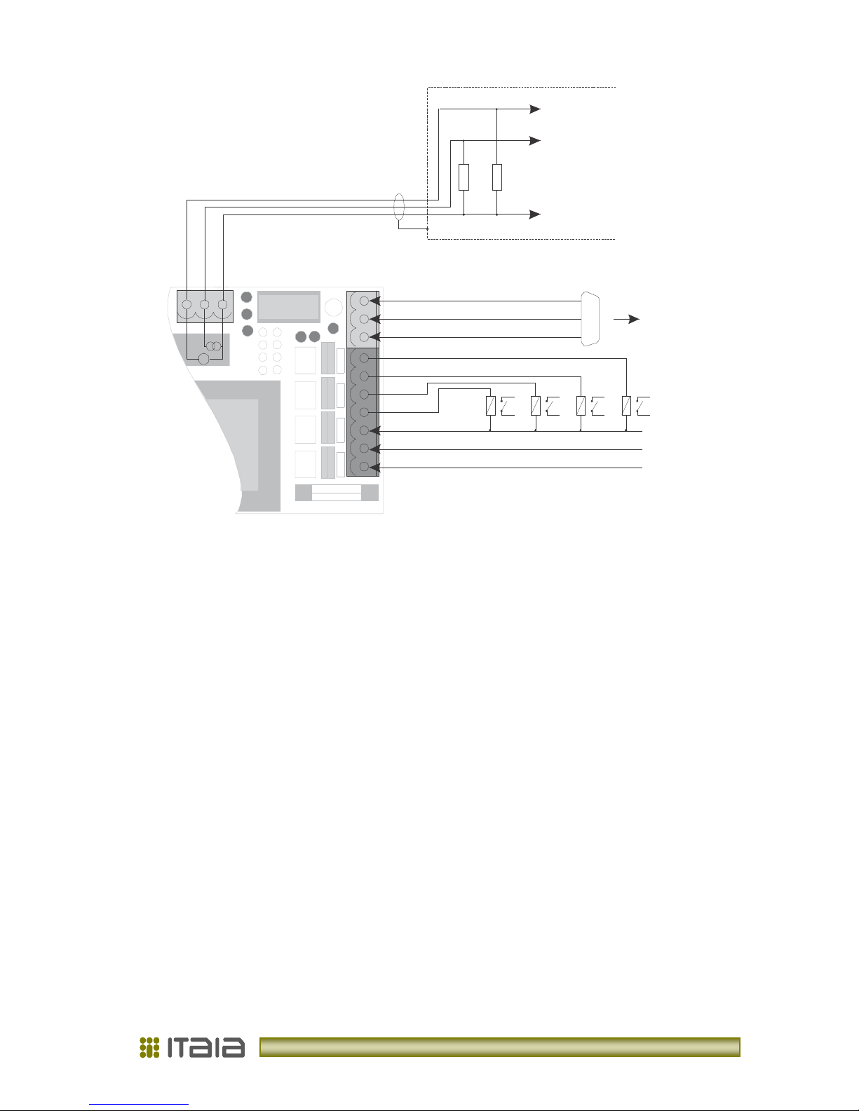
2. 3. Connecting
Photometer is connected to the mains power supply 230 VAC and to the tunnel light
regulating system. Cables with 3-7 leads at minimum 0.75 mm
2
must be used for 230 VAC
power outputs. For analogue U/I output coaxial 2-3 lead data cable is recommended.
Maximum connection distance is up to 400 metres. Cable inlet via glands must be well
tightened after the connection. For the parametric setup connect photometer with personal
computer and run software. Connection distance can be up to 20 metres for RS-232 (200 m
for RS-485 –optional).
All necessary connectors are accessible by removing rear cover (see Pictures 1 and 2and
Table 1).
After final connection and successful commition place provided desiccant bag in the
photometer housing and push it towards front window. Take care it is not touching any
electrical part!