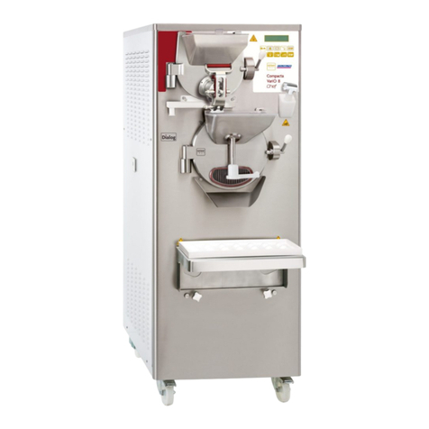
Italian Gelato 603 BIB User manual

INSTRUCTION MANUAL
603 BIB
APPLICARE
TARGA
CARATTERISTICHE
Italian Gelato Concepts Pty Limited
Unit 1, 37 Mortimer Road
Acacia Ridge Qld 4110
Bris Office: +61 (0) 7 3162 7724
Syd Office +61 (0) 2 8311 9701
Email: [email protected]
www.italiangelato.com.au

- 2 -
603 BIB
603 BIB_EN - 2015/01 - Ed. 3
Edition: 3 Date: 2015/01 3.4.2, 3.6, 5.
Editor: AM LP Approved: RL
We wish to thank you for purchasing one of Ice Team 1927 machines.
To the best guarantee, since 1993 Ice Team 1927 has submitted its own Quality
System to the certication according to the international Standard ISO 9001.
Nowadays Ice Team 1927 production has got UNI-EN-ISO 9001:2008 Certied
Quality System.
Via Emilia, 45/A- 40011 Anzola dell'Emilia (Bologna) - Italy
Tel. +39 051 6505310 - Fax +39 051 6505311
This manual contains a TRANSLATION OF THE ORIGINAL INSTRUCTIONS and may not
languages, without the prior written permission of .
the purchaser.
- Regulation 2004/1935/EC relating to “Materials and articles in contact with
foodstuffs”

- 3 - 603 BIB_EN - 2015/01 - Ed. 3
603 BIB
TABLE OF CONTENTS
FOREwORD SEC.............................................................................................................. 5
INSTRUCTION MANUAL ...................................................................................... 5
PURPOSE.................................................................................................................. 5
STRUCTURE OF THE MANUAL........................................................................... 5
....................................................................... 5
CONVENTIONAL SYMBOLS................................................................................ 6
QUALIFICATION OF THE PERSONNEL SYMBOLS.......................................... 6
SAFETY.....................................................................................................................
WARNINGS ..............................................................................................................
.................................................................................
............................................ 9
........................................... 9
1.1.3 INFORMATION ON MAINTENANCE SERVICE...................................... 9
1.1.4 INFORMATION FOR USERS ...................................................................... 9
.......................................................
1.2.1 GENERAL INFORMATION....................................................................... 10
1.2.2 MACHINE LAYOUT................................................................................... 10
1.2.3 TECHNICAL FEATURES........................................................................... 10
1.2.4 MACHINE UNIT LOCATION.....................................................................11
.....................................................................................................
......................................................................................................................
.........................................................................................
.....................................................
......................................................................................................................
.....................................................
........................................................................
.......................................................................
................................................................... 14
.........................................................................
............................................................................................................
.................................................................................................................
...........................................................................................
SEC. 3 INSTRUCTIONS FOR USE
......................................................................
..........................................................................
3.3 OPERATOR CONTROLS....................................................................................
3.3.1 MAIN SWITCH...........................................................................................
...........................................................................................................
3.4.1 ELECTRONIC CONTROL PANEL............................................................
3.4.2 FUNCTIONS................................................................................................
3.5 ICE CREAM DISPENSING HANDLE...............................................................
3.6 USER PROGRAMMING .....................................................................................
.............
.................
.............................................................. 23
............................................... 24
.............................................................................................
............................................................................................
............................................................... 24
.....................................................................................
............................................................... 24

- 4 -
603 BIB
603 BIB_EN - 2015/01 - Ed. 3
...................................................................................................
.........................................................................
4.1.1 SAFETY MAGNETIC SWITCH................................................................. 25
................................................................................................................
...........................................................................................................
PARTS IN CONTACT wITH THE PRODUCT
GENERAL INFORMATION
...................................................................................
...................................................................................
5.3 TIPS.........................................................................................................................
......................................... 30
5.5 SCHEDULED CLEANING.................................................................................. 30
5.5.1 ICE CREAM SYSTEM EMPTYING ............................................................ 30
5.5.2 REMOVING PUMP, PRESSURE SWITCH COVER, LEVEL SENSOR.. 31
........................................................................ 33
5.5.4 BEATER REMOVAL................................................................................... 33
.................................................................................................. 34
......................................... 34
................. 34
.................................................................................................. 35
5.5.9 HYGIENE....................................................................................................... 35
.................................................................... 36
SEC. 6 MAINTENANCE
....................................................................................................
...............................................................................................
6.3 AIR COOLING......................................................................................................
........................................................................
6.5 SUPPLIED SPARE PARTS TABLE....................................................................
........................................................................................

- 5 - 603 BIB_EN - 2015/01 - Ed. 3
603 BIB
FOREwORD
INSTRUCTION MANUAL
The European Community directions on safety standards as well as on free circulation of industrial
products within the E.C. were taken into due account when editing this manual.
PURPOSE
the long run quality features characterizing
necessary procedures during cleaning as well as routine and special maintenance.
Via Emilia, 45/A - 40011Anzola dell'Emilia (Bologna) - Italy
Tel. +39 051 6505310 - Fax +39 051 6505311
STRUCTURE OF THE MANUAL
Chapter
- the Operator must read the chapters concerning machine start-up and operation of machine
components;
must read all parts of this manual.
ADDITIONAL DOCUMENTATION
-
machine for its maintenance.
-

- 6 -
603 BIB
603 BIB_EN - 2015/01 - Ed. 3
described may cause an electric shock.
CAUTION: DANGER FROM HIGH TEMPERATURES
following safety rules.
NOTE
It points out signicant information for the personnel involved.
wARNINGS
and damage to the machine.
PERSONAL PROTECTION DEVICES
This symbol on the side means that the operator must use personal protection against an implicit
risk of accident.
MACHINE OPERATOR
andunloadingofproductsused during production, the loadingofanyconsumablematerials,basic
maintenance operations, (cleaning, simple blockages, inspections of the instrumentation, etc.).
He/she is a skilled engineer, capable of operating the machine under normal conditions; he/she is
under particular conditions or in accordance with agreements made with the machine's owner.

603 BIB_EN - 2015/01 - Ed. 3
603 BIB
serious damage to persons and things.
- only original spare parts are used especially as far as those components with safety functions
- such documentation must be carefully read and requirements must consequently be met;
- only suitably skilled personnel should be assigned to electrical equipment;
- access is forbidden to children or any unauthorized persons.
IMPORTANT!
NOTE:
According to the standard in force, a SKILLED ENGINEER is a person who, thanks to:
- training, experience and education,
- knowledge of rules, prescriptions and interventions on accident prevention,
- knowledge of machine operating conditions,
is able to realize and avoid any danger and has also been allowed by the person in charge of
plant safety to carry out all kinds of interventions.
wARNINGS
the machine, insert a single-phase differential magnetothermal protection switch on both
magnetothermal section with 10Arated current, type-B differential section with 30 mArated
cleaning. Before carrying out any maintenance operation, make sure that the machine is in
“STOP” position and that the main switch has been cut out.
disconnecting it from the power supply.
- The place of installation must not be exposed to water sprays, high moisture, heat or steam sources.
- will not be held responsible for any accidents that might happen during
fully complied with.

603 BIB
603 BIB_EN - 2015/01 - Ed. 3

- 9 - 603 BIB_EN - 2015/01 - Ed. 3
603 BIB
.....................................................................................................
.........................................................................................................
....................................................................................................
............................................................................................
.......................................................................................
.........................................................................................
All operations of routine maintenance are here described in section “Maintenance”; any
and information about its operation.
- In case of need, please call the local distributor - or the manufacturer, if no distributor is
described in this manual without prior notice.
- The description and illustrations contained in this document are not binding.
- All copyrights on this manual belong to .
and serial number assigned to it when it was manufactured.
Legend:
A=Serial number
B=Machine type
C
D=Fuse rating
E=Gas type and weight
F= Machine code
G=Condensation type
A=Air
W=Water
H=Frequency
I= Power
V Hz kW
A
Gas kg
Cod.
Serial No.
A B
C D E H
F G
I

- 10 -
603 BIB
603 BIB_EN - 2015/01 - Ed. 3
accommodated in chilled cabinet.
recommends to always use high quality mix for ice cream production in order to
companies.
Make sure your staff always keeps the machine clean.
.
NOTE
The dimensions reported below may change depending on type of condensation.
T
The following characteristics are purely indicative. Ice Team reserves the right to make all the changes whenever necessary
and without being bound to previous statements to the purchaser.
Hourly production may very depending on the type of mix used, its feeding temperature and the characteristics of the
desired nal product.
Model Hourly
production Capacity Flavors Electrical supply Installed
power Condensation Dimensions Net
Weight
Hopper Bag in Box
kg L L n Volt Cycle Phase kW Width Depth Height kg
603 BIB 60 12+12 10+10 2+1 400 50 3 5 Air/Water 54 90 air
80 water 163 285

- 11 - 603 BIB_EN - 2015/01 - Ed. 3
603 BIB
603 BIB models must only be used conforming with contents of paragraph 1.2.1 "General
Any use of the machine non compliant with the intended use is not allowed.
wARNING
Legend:
Control panel
Ice Cream spigot door
3Chilled compartment/cabinet
On/Off main switch
5
6Condensate collector tray
5
3
6

- 12 -
603 BIB
603 BIB_EN - 2015/01 - Ed. 3
The machine must be stored in a dry and dump-free place.
Before storing the machine, wrap it in a cloth in order to protect it against dust or other impurities.
laws in force in machine installation country.
this symbol on the side of the product or packaging means that the product must not be disposed
returning it to a collection point designated for the recycling of unused electrical and electronic
For more information concerning the correct disposal of this product, please contact your local
authority or the retailer where this product was purchased.

- 13 - 603 BIB_EN - 2015/01 - Ed. 3
603 BIB
The machine must be installed in such a way that air can freely circulate all around its sides.
Enough room must be left free around the machine, in order to enable the operator to act without
accessing the working area should be at least 150 cm, which takes into account the space taken
up by open doors, if any.
wARNING
wARNING
NOTE
An insufcient air circulation affects operation and output capacity of the machine.
150 cm
10 cm 10 cm
50 cm
ACC

- 14 -
603 BIB
603 BIB_EN - 2015/01 - Ed. 3
to a cooling tower.
hourly consumption shown in table Sect. 2 - § 2.2.3. Water consumption increases if
wARNING
standstill and water starts circulating when refrigeration system is turned on
Before connecting the machine to the power supply line, check that the characteristics of the
Connect the machine to the power supply line, installing a magnetothermal protection switch with
same as the one shown in the data plate (at the symbol of the fuse element “ ”).
The number of poles of the disconnector must be the same as the number of phases, plus
MUSTALWAYS be connected to the light blue cable of the machine power cable.
differential release coil and with a differential current of max. 30 A.
wARNING
wARNING
wARNING

- 15 - 603 BIB_EN - 2015/01 - Ed. 3
603 BIB
wARNING
Motor installed in the machine is of the type with lubrication for life; no action of checking/replacing
or topping up is necessary.
able to determine the reason of such occurrence.
Machine test at the end user's premises must be carried out by authorized technical personnel or
After positioning the machine and connecting it properly to the supply lines, proceed with the
operations related to the functional check and with the operating test of the machine.

- 16 -
603 BIB
603 BIB_EN - 2015/01 - Ed. 3

603 BIB_EN - 2015/01 - Ed. 3
603 BIB
3. INSTRUCTIONS FOR USE
cause serious damage to persons and things.
- Only original spareparts are used especially asfar as those componentswith safety functions
- Such documentation must be carefully read and requirements must consequently be met.
- Only suitably skilled personnel should be assigned to electrical equipment.
Feed mix into the suitable tubs accommodated in the cabinet and start the automatic production
cycle, until ice cream reaches the ideal consistency set by ; use the minimum and
cycle ends, the soft ice cream can be extracted through the spigot door.
3.3 OPERATOR CONTROLS
Turn switch (Ref.1) to "1" to turn on the machine. Turn it to "0" to turn it off.
Ice cream
(nished product)
Ice cream mix

603 BIB
603 BIB_EN - 2015/01 - Ed. 3
B
STOP Button
FromStopitispossibletoaccessanymachinefunction. It is always NECESSARY
and an intermittent beep will be emitted, so as to alert the user to set the machine
to Production or Storage modes.
The display will read
Ice cream Ready!
only (as in “Ready Wait” which indicates that ice cream is ready on side 1 only) .
cream has not yet reached its set consistency and it is therefore necessary to wait.
The second line indicates the cabinet temperature followed by the number of
days until the next required washing (W= Wash).
Cabinet ¤
¤¤
¤
¤
E
symbol according to its function.
When the touchpad accepts a command it will produce a beeping sound.

- 19 - 603 BIB_EN - 2015/01 - Ed. 3
603 BIB
Set=100 Set=090
consistency in the cylinders. To change consistency, see paragraph 3.6 "User
programming".
1234 1234 1234
- after midnight
Total Cones
This window shows the Total Cones, i.e. the total number of cones dispensed
This window shows the operating hours of the pump tube expressed in hours
Note:
After replacing the pipes that have reached the maximum number of operating
hours, the user may reset the counters from this page by opening the protection
cover of one or both pumps and holding the production key pressed for 3”. Now
it is possible to close the cover of the relevant pump (see also "Change Pipe 1"
in the alarm section).
TE1-013 TE2-012
TC1 = Cylinder 1 Thermostat
TC2 = Cylinder 2 Thermostat
TEV = Cabinet Thermostat
INCREASE Button

- 20 -
603 BIB
603 BIB_EN - 2015/01 - Ed. 3
STORAGE/DECREASE Button
When this button is pressed, the temperature of the product in the cabinet and in
where edits are permitted.
CABINET STORAGE
indicate that the set function must keep only the cabinet to the set temperature.
only in the cabinet.
wARNING
Cabinet ¤
¤
utton
When this button is pressed, the pumps runs for 3 minutes and then the
machine automatically returns to Stop.
Pump ON
Beater ON
The pump is stopped, whereas the beater keeps running for maximum 3 minutes.
Beat + Pump ON
Beater and pump run for 30".
Press Cleaning key again to return to start page.
To facilitate machine cleaning, hold the Cleaning button pressed for 3 seconds
enable the buttons, press the Cleaning button again for 3 seconds; the machine
will stay in the same mode as when the buttons were disabled.
Table of contents
Other Italian Gelato Ice Cream Maker manuals

Italian Gelato
Italian Gelato ICETEAM 1927 STARGEL 4 User manual

Italian Gelato
Italian Gelato ICETEAM 1927 STARGEL 5 manual

Italian Gelato
Italian Gelato MISSOFTY User manual

Italian Gelato
Italian Gelato CATTABRIGA MANTEMATIC K20S manual

Italian Gelato
Italian Gelato ICETEAM EASY MIX PLUS User manual
Popular Ice Cream Maker manuals by other brands

Hamilton Beach
Hamilton Beach 68880 instructions

Wolfgang Puck
Wolfgang Puck BPCR05US1 Bistro collection Use and care

Cuisinart
Cuisinart ICE-25BC - Classic Frozen Yogurt Recipe booklet

Sunbeam
Sunbeam SNOWY GL5400 Service manual

Bartscher
Bartscher 135.001 instruction manual

SaniServ
SaniServ 407 Cleaning instructions