Italian Gelato ICETEAM EASY MIX PLUS User manual

INSTRUCTION MANUAL
EASY MIX PLUS
Code IC193-008613_03
Italian Gelato Concepts Pty Limited
Unit 1, 37 Mortimer Road
Acacia Ridge Qld 4110
Bris Office: +61 (0) 7 3162 7724
Syd Office +61 (0) 2 8311 9701
Email: [email protected]
www.italiangelato.com.au

- 2 -
EASY MIX PLUS
Easy Mix Plus - 2018/07 - Rev. 03
EN
We wish to thank you for purchasing one of ICETEAM 1927 machines.
To the best guarantee, since 1993 ICETEAM 1927 has submitted its own Quality
System to the certication according to the international Standard ISO 9001.
Nowadays ICETEAM 1927 production has got UNI-EN-ISO 9001 Certied Quality
System.
Revision: 03 Date: 2018/07 Modications:
Editor: AM Veried: DN Approved: RL
Moreover, ICETEAM 1927 machines comply with the following European
Directives:
- “Machinery” Directive 2006/42/EC,
- “Low Voltage” Directive 2014/35/EU,
- “EMC” Directive 2014/30/EU,
- “PED” Directive 2014/68/EU,
- Regulation 2004/1935/EC relating to “Materials and articles in
contact with foodstuffs”
- Regulation 2023/2006/EC "Good manufacturing practice for
materials and articles intended to come into contact with food"
ICETEAM 1927
Via Emilia, 45/A - 40011 Anzola dell'Emilia (Bologna) - Italy
Tel. +39 051 6505330 - Fax +39 051 6505331
This manual contains a TRANSLATION OF THE ORIGINAL INSTRUCTIONS and may not
be reproduced, transmitted, transcribed, led in a data retrieval system or translated into other
languages, without the prior written permission of ICETEAM 1927.
The purchaser has the right to reprint it for his own ofce use.
ICETEAM 1927 policy pursues a steady research and development, thus it reserves the right to
make changes and revisions whenever deemed necessary and without being bound to notifying
the purchaser.

EASY MIX PLUS
- 3 - Easy Mix Plus - 2018/07 - Rev. 03 EN
TABLE OF CONTENTS
INTRODUCTION SEC...................................................................................................... 5
INSTRUCTION MANUAL ...................................................................................... 5
PURPOSE.................................................................................................................. 5
STRUCTURE OF THE MANUAL........................................................................... 5
ADDITIONAL DOCUMENTATION ....................................................................... 5
CONVENTIONAL SYMBOLS................................................................................ 6
QUALIFICATION OF THE PERSONNEL SYMBOLS.......................................... 6
SAFETY..................................................................................................................... 7
WARNINGS .............................................................................................................. 7
SEC. 1 GENERAL INFORMATION
1.1 GENERAL INFORMATION ................................................................................. 9
1.1.1 MANUFACTURER IDENTIFICATION DATA............................................ 9
1.1.2 INFORMATION ON MAINTENANCE SERVICE...................................... 9
1.1.3 INFORMATION FOR USERS ...................................................................... 9
1.2 INFORMATION ABOUT THE MACHINE......................................................... 9
1.2.1 GENERAL INFORMATION......................................................................... 9
1.2.2 TECHNICAL FEATURES........................................................................... 10
1.2.3 MACHINE UNIT LOCATION.....................................................................11
1.3 INTENDED USE.....................................................................................................11
1.4 NOISE......................................................................................................................11
1.5 MACHINE STORAGE..........................................................................................11
1.6 DISPOSAL OF PACKAGING MATERIALS......................................................11
1.7 WEEE (Waste Electrical and Electronic Equipment)........................................ 12
SEC. 2 INSTALLATION
2.1 ROOM NECESSARY FOR MACHINE USE..................................................... 13
2.2 WATER SUPPLY CONNECTION....................................................................... 13
2.3 MACHINES WITH AIR-COOLED CONDENSER .......................................... 13
2.4 MACHINES WITH WATER-COOLED CONDENSER................................... 14
2.4.1 WATER VALVE ADJUSTMENT ................................................................ 14
2.5 ELECTRIC CONNECTION................................................................................ 14
2.5.1 EQUIPOTENTIAL CONNECTION............................................................ 14
2.5.2 REPLACING THE POWER CABLE.......................................................... 14
2.6 POSITIONING THE MACHINE ........................................................................ 15
2.7 TOP-UPS................................................................................................................. 15
2.8 MACHINE TESTING........................................................................................... 15
SEC. 3 INSTRUCTIONS FOR USE
3.1 MACHINE SAFETY WARNINGS ...................................................................... 17
3.2 MACHINE CONFIGURATION.......................................................................... 17
3.3 CONTROLS........................................................................................................... 18
3.3.1 PUSH-BUTTON PANELS........................................................................... 18
3.3.2 EASY MIX 60 PLUS FUNCTIONS............................................................ 18
3.3.3 EASY MIX 120 PLUS FUNCTIONS.......................................................... 21
3.4 MACHINE STARTING ........................................................................................ 24
3.4.1 EASY MIX 60 PLUS ................................................................................... 24
3.4.2 EASY MIX 120 PLUS ................................................................................. 25
3.4.3 USE OF THE MIX DISPENSING SPIGOT................................................ 26
3.5 USER PROGRAMMING ..................................................................................... 27

- 4 -
EASY MIX PLUS
Easy Mix Plus - 2018/07 - Rev. 03
EN
SEC. 4 SAFETY DEVICES
4.1 MACHINE SAFETY SYSTEMS ......................................................................... 29
4.2 BLACKOUT........................................................................................................... 30
SEC. 5CLEANING, REMOVING AND REFITTING OF PARTS IN CONTACT
WITH THE PRODUCT
5.1 GENERAL INFORMATION ............................................................................... 31
5.2 WASHING CONDITIONS ................................................................................... 31
5.3 TIPS......................................................................................................................... 31
5.4 HOW TO USE CLEANING/SANITIZING SOLUTION.................................. 32
5.5 PRELIMINARY CLEANING.............................................................................. 32
5.6 SPIGOT PISTON REMOVAL.............................................................................. 32
5.7 DISASSEMBLY OF HOPPER LID..................................................................... 33
5.8 DISASSEMBLY OF BEATER (EASY MIX 60 PLUS) ...................................... 33
5.9 DISASSEMBLY OF AGITATOR (EASY MIX 120 PLUS) ............................... 34
5.9.1 AGITATOR REFITTING............................................................................. 34
5.10 HYGIENE............................................................................................................... 35
5.11 SANITIZATION.................................................................................................... 35
SEC. 6 MAINTENANCE
6.1 SERVICE TYPE .................................................................................................... 37
6.2 WATER COOLING............................................................................................... 37
6.3 AIR COOLING...................................................................................................... 37
6.4 ORDERING SPARE PARTS................................................................................ 38
6.5 SUPPLIED ACCESSORIES................................................................................. 38
SEC. 7 TROUBLESHOOTING

EASY MIX PLUS
- 5 - Easy Mix Plus - 2018/07 - Rev. 03 EN
INTRODUCTION
INSTRUCTION MANUAL
TheEuropeanCommunitydirectionsonsafetystandardsaswellasonfreecirculationofindustrial
products within the E.C. were taken into due account when editing this manual.
PURPOSE
This handbook was conceived taking machine users' needs into due account.
Topics relevant to a correct use of the machine have been analyzed in order to keep unchanged
in the long run quality features characterizing ICETEAM 1927 machines all over the world.
A signicant part of this manual refers to the conditions necessary for the machine use and to the
necessary procedures during cleaning as well as routine and special maintenance.
Nevertheless, this manual cannot cover any possible need in detail. In case of doubts or missing
information, please contact:
ICETEAM 1927 Via Emilia, 45/A - 40011 Anzola dell'Emilia (Bologna) - Italy
Tel. (+39) 051 6505330 - Fax (+39) 051 6505331
STRUCTURE OF THE MANUAL
This manual is divided in sections, chapters and sub chapters for an easy reference.
Section
A section is the part of the manual identifying a specic topic related to a machine part.
Chapter
A chapter is that part of a section describing an assembly or concept relevant to a machine part.
Sub chapter
It is that part of a chapter detailing the specic component of a machine part.
It is necessary that each person involved in the machine operation reads and understands those
parts of the manual of his/her own concern, and particularly:
the Operator must read the chapters concerning machine start-up and operation of machine
components;
A qualied Engineer involved in the installation, maintenance, repair, etc., of the machine
must read all parts of this manual.
ADDITIONAL DOCUMENTATION
Along with an instruction manual, each machine is also supplied with additional documentation:
Supplied spare parts: a list of spare parts which is delivered together with the machine for
its maintenance.
Wiring diagram: a diagram of wiring connections is placed in the machine.
Installation sheet: To be completed by the installer. Return a copy to the customer, the
dealer and the manufacturer in order to activate the machine warranty
Before using the machine read carefully the instruction manual.
Pay attention to the safety instructions.

- 6 -
EASY MIX PLUS
Easy Mix Plus - 2018/07 - Rev. 03
EN
CONVENTIONAL SYMBOLS
CAUTION: ELECTRIC SHOCK HAZARD
The staff involved is warned that the non-observance of safety rules in carrying out the operation
described may cause an electric shock.
CAUTION: DANGER FROM HIGH TEMPERATURES
This warns the staff involved that failure to abide by safety rules in carrying out the operation
described involves the risk of burns and scalds.
CAUTION CRUSHING HAZARD
This warns the staff involved that failure to abide by safety rules in carrying out the operation
described involves the risk of suffering crushed ngers or hands.
CAUTION: GENERAL HAZARD
The staff involved is warned that the operation described may cause injury if not performed
following safety rules.
NOTE
It points out signicant information for the personnel involved.
WARNINGS
This warns the personnel involved that the non-observance of warnings may cause loss of data
anddamage tothe machine, or cause risksfor noncompliancewith any applicablelaw/regulations
PERSONAL PROTECTION DEVICES
This symbol on the side means that the operator must use personal protection against an implicit
risk of accident.
EQUIPOTENTIAL CONNECTION
For connecting all appliances with this type of connection.
Warning: do not connect to ground.
QUALIFICATION OFTHE PERSONNEL SYMBOLS
The personnel allowed to operate the machine can be differentiated by the level of preparation
and responsibility in:
OPERATOR
Unqualied personnel, without any specic technical abilities, capable of carrying out simple
jobs, such as: operating the machine using the commands available on the keypad, the loading
andunloadingof products usedduringproduction, the loadingofany consumable materials, basic
maintenance operations, (cleaning, simple blockages, inspections of the instrumentation, etc.).
QUALIFIED ENGINEER
He/she is a skilled engineer, capable of operating the machine under normal conditions; he/she is
able to carry out operations on mechanical parts and all adjustments, as well as maintenance and
repairs. He/she is qualied for interventions on electrical and refrigeration components.
ICETEAM 1927 TECHNICIAN
He/she is a qualied engineer the manufacturer entrusted with complex operations under particular
conditions or in accordance with agreements made with the machine's user.

EASY MIX PLUS
- 7 - Easy Mix Plus - 2018/07 - Rev. 03 EN
SAFETY
When using industrial equipment and plants, one must be aware of the fact that moving parts
(rotarymotion), highvoltage components, aswell as partssubject tohigh temperatures maycause
serious damage to persons and things.
The persons in charge of safety must ensure that:
any incorrect use or handling is avoided;
the safety devices are neither removed nor tampered with;
the machine is regularly serviced;
only original spare parts are used, especially in the case of safety-related components
(e.g.: protection microswitches, thermostats).
suitable personal protective equipment is used;
high care is taken during hot product cycling.
To achieve the above, the following is necessary:
at the work station an instruction manual relevant to the machine should be available;
such documentation must be carefully read and requirements must consequently be met;
only adequately skilled personnel should be assigned to electrical equipment; this appliance is
not intended for use by persons (including children) with reduced physical, sensory or mental
capabilities, or lack of experience and knowledge, unless they have been given supervision or
instruction concerning use of the appliance by a person responsible for their safety;
Make sure that no technician will ever carry out interventions outside his/her own knowledge
and responsibility sphere;
Children should be supervised to ensure that they do not play with the appliance.
IMPORTANT!
Make sure that the personnel do not perform operations out of their range of knowledge and
responsibility (refer to “Qualication of the personnel symbols”).
NOTE:
According to the standard in force, a QUALIFIED ENGINEER is a person who, thanks to:
- training, experience and education,
- knowledge of rules, prescriptions and interventions on accident prevention,
- knowledge of machine operating conditions,
It is able to realize and avoid any danger and has also been allowed by the person in charge of
plant safety to carry out all kinds of interventions.
WARNINGS
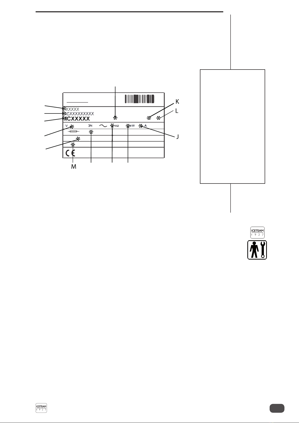
The machine must be installed in compliance with current installation regulations.
When installing the machine, insert a differential magnetothermal protection switch on all poles
of the line, adequately sized to the absorption power shown on machine identication plate and
with a contact opening of 3 mm at least.
Neverperformoperationsonthemachineusingyourhands,duringbothproductionandcleaning.
Beforecarryingoutanymaintenanceoperation,makesurethatthemachineisin“STOP” position
and that the main switch has been cut out.
It is forbidden to wash the machine by means of a jet of pressurized water.
Itisforbiddentoremovepanelsinordertoreachthemachineinternalpartsbeforedisconnecting
the machine from the power supply.
The place of installation must not be exposed to water sprays, high moisture, heat or steam
sources.
Do not store explosive substances or spray cans inside the machine, nor aerosol cans
containing ammable propellant.
ICETEAM 1927 is not responsible for any accident that might happen during operation,
cleaning and/or servicing of its machines if this warning has not been fully complied with.

- 8 -
EASY MIX PLUS
Easy Mix Plus - 2018/07 - Rev. 03
EN

EASY MIX PLUS
- 9 - Easy Mix Plus - 2018/07 - Rev. 03 EN
1. GENERAL INFORMATION
1.1 GENERAL INFORMATION
1.1.1 Manufacturer identication data
Themachinehasadataplatecarryingmanufacturerdata,machinetypeandserialnumber,assigned
when manufactured.
Copy of machine data plate to be found on rst page of this manual.
1.1.2 Information on maintenance service
All operations of routine maintenance are here described in section “Maintenance”; any additional
operationrequiringtechnicaloperationonthemachinemustbeagreeduponwiththemanufacturer,
who will also examine the possibility of a factory technician eld operation.
1.1.3 Information for users
- The manufacturer of the machine described in this manual is available for any
clarication and information about its operation.
- In case of need, please call the local distributor - or the manufacturer, if no distributor is
available in the country of the user.
- The manufacturer's service department is available for any information about operation,
and requests of spare parts and service.
- The manufacturer reserves the right to make any changes deemed necessary to the
machine described in this manual without prior notice.
- The descriptions and illustrations contained in this document are not binding.
- All copyrights on this manual belong to ICETEAM 1927
1.2 INFORMATION ABOUT THE MACHINE
1.2.1 General information
Easy Mix Plus are pasteurizers which prepare, pasteurize, and age ice cream mixes.
An electronic microprocessor steadily checks each process cycle selected. An alphanumerical
display shows all steps of a process cycle and sends audio-visual messages.
The following are the main components:
control panel with low voltage 24 V controls;
electrical, freezing and soundproong units complying with international standards;
graduated hopper;
water dispenser for wash;
high-resistance steel frame, treated with rust inhibitors; painted aluminum panels.
Refr.
A
B
C
F
G
E
H
D I
Legend:
A= Serial number
B= Machine type
C= Supply voltage
D= Fuse rating
E= Gas type and weight
F= Machine code
G= Condensation type
A=Air
W=Water
H= Frequency
I= Power
J= Rated current
K= IP code
L= Climate class
M= Greenhouse effect gas
quantity

- 10 -
EASY MIX PLUS
Easy Mix Plus - 2018/07 - Rev. 03
EN
** Other supply voltage ratings are available. For specic values, refer to the identication plate applied to the
machine and on the rst page of this manual.
Note
The dimensions reported below may change depending on type of condensation.
Performance refers to a 25°C room temperature and 20°C cooling water temperature.
ICETEAM 1927 recommends to always use high quality ingredients for the preparation of
confectionery products, in order to satisfy your customers, even the most demanding ones. Any
savingmadetotheprejudiceofqualitywillsurelyturnintoalossmuchbiggerthanthesavingitself.
Bearing in mind the above statements, please into consideration the following:
choose high quality natural ingredients and create your own mix or buy it from trustworthy
suppliers;
closely follow instructions given by your supplier;
do not modify the recommended recipes without knowing the ingredient characteristics;
taste your ice-cream before serving and start selling only if entirely satisfactory;
make sure your staff always keeps the machine clean.
Always have your machine serviced by companies authorized by ICETEAM 1927.
1.2.2 Technical features
Model
Production Power supply** Installed
power Condenser
Dimensions in cm Net
Weight
Min
Kg Max
Kg Volt Hz Ph kW Width Depth Height kg
Easy mix 60
Plus 30 60 400 50 3 9 water 39 85 103 162
Easy mix
120 Plus 40 120 400 50 3 18.5 water 64 85 103 240

EASY MIX PLUS
- 11 - Easy Mix Plus - 2018/07 - Rev. 03 EN
1.3 INTENDED USE
Easy Mix Plus machines must only be used in compliance with what described in paragraph 1.2.1
"General Information", within the functional limits described below:
Voltage: ±10%
Min. air temperature in °C: 10°C
Max. air temperature in °C: 43°C
Min. water temperature: 10°C
Max. water temperature: 30°C
Min. water pressure: 0.1 MPa (1 bar)
Max. water pressure: 0.5 MPa (5 bar)
Max. air relative humidity: 85%
- This machine has been designed for use in rooms not subject to explosion-proof laws; its use
is thus bound to complying rooms and normal atmosphere.
1.4 NOISE
The equivalent continuous A-weighted sound pressure level in a workplace for water-cooled as
well as air-cooled machines is less than 70 dB(A).
1.5 MACHINE STORAGE
The machine must be stored in a dry and damp-free place.
Before storing the machine, wrap it in a cloth in order to protect it against dust or other impurities.
1.6 DISPOSAL OF PACKAGING MATERIALS
When opening the packing crate, divide packing stuff per type and get rid of them according to
laws in force in machine installation country.
1.2.3 Machine unit location
Legend:
1Hopper with lid
2Control panel
3Dispensing spigot
4Shower

- 12 -
EASY MIX PLUS
Easy Mix Plus - 2018/07 - Rev. 03
EN
1.7 WEEE (Waste Electrical and Electronic Equipment)
In conformity with the European Directives 2006/66/EC, on batteries and accumulators and waste
batteries and accumulators, and 2002/96/EC, also known as WEEE, the presence of the symbol on
the side of the product or packaging means that the product must not be disposed of with normal
urban waste. Instead, it is the user’s responsibility to dispose of this product by returning it to a
collection point designatedfor the recycling/treatment of electrical andelectronic equipment waste.
Separate collection of this waste helps to optimize the recovery and recycling of any reclaimable
materials and also reduces the impact on human health and on the environment.
For more information concerning the correct disposal of this product, please contact your local
authority or the retailer where this product was purchased.

EASY MIX PLUS
- 13 - Easy Mix Plus - 2018/07 - Rev. 03 EN
2. INSTALLATION
2.1 ROOM NECESSARY FOR MACHINE USE
The machine must be installed in such a way that air can freely circulate all around its sides.
Enough room must be left free around the machine, in order to enable the operator to act without
constraint and also to immediately leave working area, if necessary.
The minimum access space to working area should be at least 150 cm.
WARNING
MACHINES WITHAIR-COOLED CONDENSER must be installed AT LEAST 50 CM
AWAY FROM THE BACK WALL in order to allow free air circulation around the condenser.
NOTE
An insufcient air circulation affects operation and output capacity of the machine.
2.3 MACHINES WITH AIR-COOLED CONDENSER
Machines with air-cooled condenser must be installed at least 50 cm away from the back wall in
order to allow free air circulation around the condenser.
Frequently clean the oor under and around the machine. This prevents paper and other foreign
bodies from obstructing regular air ow.
The condenser must be cleaned every month to remove any dust, paper, etc. that can clog it,
adversely affecting the normal operation of the machine.
Note
An insufcient air circulation affects operation and output capacity of the machine.
2.2 WATER SUPPLY CONNECTION
The machine must be connected to the water supply, which must not exceed a pressure of 0.5
MPa (5 bar).
In air-cooled machines, water connection for drinking water (for machine wash) is placed under
the machine.
In water-cooled machines water connections (for machine wash and gas cooling) are placed on
rear panel.
Dimensions in cm
lllllllllllllllll
50
10
60
150

- 14 -
EASY MIX PLUS
Easy Mix Plus - 2018/07 - Rev. 03
EN
2.4 MACHINES WITH WATER-COOLED CONDENSER
On machines with water-cooled condenser, water connections (for machine wash and gas cooling) are
placed on the rear panel. The connections are three, all aligned along the same vertical line. Machines
tted with a water-cooled condenser need to be connected to running water supply or to a cooling tower.
Water must have a pressure of 0.1 MPa (1 bar) at least, and a ow rate at least equal to the
estimated hourly consumption.
Connect inlet pipe marked by plate “Water Inlet” to water supply installing a shut-off valve, and
outlet pipe marked by plate “Water Outlet” to a drain pipe, installing a shut-off valve.
2.4.1 Water valve adjustment
IMPORTANT
If water valve must be reset, this operation shall be carried out by skilled personnel, only.
Valve adjustment must be carried out in such a way that no water ows when machine is off and
lukewarm water ows when machine is on.
NOTE:
Water consumption increases if temperature of inlet water is above 20 °C.
WARNING:
Do not leave the machine in a room with temperature below 0°C without draining water
from the condenser.
2.5 ELECTRIC CONNECTION
The power supply system must comply with the national regulations in force in the place of
installation and provided with an efcient ground connection.
The manufacturer is not responsible for any malfunction or for injury to persons and/or damage
to property resulting from connection to a non-compliant electrical system.
The appliance must be installed according to the current regulations for electrical installation,
by competent and qualied technical personnel meeting the technical and professional
requirements provided for by the legislation in force in the country of installation.
Before connecting the machine to the mains, check that the mains characteristics meet those of
the machine specied in the identication plate applied to the machine itself.
Check that the power supply network is provided with a disconnection device, in compliance
with the installation rules, ensuring complete disconnection from the mains for each pole
(differential circuit breaker), in the conditions of overvoltage category III. The opening
distance of contacts must be at least 3 mm.
Check that the trip level of the differential circuit breaker is ≤ 30mA.
The machine is supplied with power cable; in case of three-phase machine with neutral, the
blue conductor of the power supply cable must be connected to the system neutral.
WARNING
The machine is tted with an electric supply cable including a yellow/green cable, which
MUST be connected to an appropriate grounding of the electric system.
2.5.1 Equipotential connection
Connection to external equipotential terminal is indicated by symbol.
It is present on the side or on the back of the machine, not to be connected to the protection ground.
The conductor to be used has a cross-section at least equivalent to the one of the connected
conductor with greatest cross-section.
2.8.2 Replacing the power cable
If the machine power cable is damaged, replace it immediately with a cable with the same features.
Replacement must be carried out by qualied personnel only.

EASY MIX PLUS
- 15 - Easy Mix Plus - 2018/07 - Rev. 03 EN
Rotation direction inversion (for Easy Mix 60 Plus only)
To reverse the rotation direction, when wrong, it is necessary to interchange two of the three leads
coming from the differential magnetothermal protection switch.
2.6 POSITIONING THE MACHINE
The machine is tted with wheels for easier positioning. The wheels feature mechanical lock mechanisms
which, once engaged, prevent the machine from moving and shifting to a different position.
2.7 TOP-UPS
Motorinstalled in the machine is of the type withlubricationforlife;noactionofchecking/replacing
or topping up is necessary.
Gas lling necessary to the circuit is carried out at ICETEAM 1927 factory during the machine
post production testing; top-ups or lling are not required if the machine is new.
If any gas top-up or lling becomes necessary, this must be made solely by qualied engineers,
able to determine the reason of such occurrence.
2.8 MACHINE TESTING
The machine is tested after production at ICETEAM 1927's premises; the requested operational
and production functions are inspected and veried.
Machine test at the end user's premises must be carried out by authorized technical personnel or
by one of ICETEAM 1927 engineers. Once the machine has been positioned and connected to
its supply lines, it is possible to carry out the operations required for machine functional check
and operating test.

- 16 -
EASY MIX PLUS
Easy Mix Plus - 2018/07 - Rev. 03
EN

EASY MIX PLUS
- 17 - Easy Mix Plus - 2018/07 - Rev. 03 EN
3. INSTRUCTIONS FOR USE
3.1 MACHINE SAFETY WARNINGS
When using industrial equipment and plants, one must be aware of the fact that moving parts
(rotarymotion), high voltagecomponents, as wellas parts subjectto hightemperaturesmay cause
serious damage to persons and things.
The persons in charge of safety must ensure that:
-an incorrect use or handling shall be avoided;
-the safety devices are neither removed nor tampered with;
-the machine is regularly serviced;
-only original spare parts are used, especially in the case of safety-related components
(ex.: protection microswitches, thermostats);
-suitable personal protective equipment is used;
-high care must be paid during hot product cycling.
To achieve the above, the following is necessary:
-at the work station an instruction manual relevant to the machine should be available;
-such documentation must be carefully read and the instructions must be strictly followed;
-onlyadequatelyskilled personnel shouldbeassignedto electrical equipmentandmachineries;
this appliance is not intended for use by persons (including children) with reduced physical,
sensory or mental capabilities, or lack of experience and knowledge, unless they have been
given supervision or instruction concerning use of the appliance by a person responsible for
their safety;
- Make sure that no technician will ever carry out interventions outside his/her own knowledge
and responsibility sphere;
- Children should be supervised to ensure that they do not play with the appliance.
3.2 MACHINE CONFIGURATION
Themachineconsistsofamotor for beater assembly, aheating and coolingsystem withair-cooled
or water-cooled condenser.
The product is prepared by pouring a mix into the hopper and starting the production cycle, while
referring to minimum and maximum quantities reported in the table in paragraph 1.2.2.
When the cycle ends, the product can be extracted using the special spigot.
WARNING
In any case, do not touch the spigot door during the heating stage or the stages
immediately after, since it can reach very high temperatures.
WARNING
Be very careful during the processing/extraction of hot products – coming into
contact with the product could cause burns.

- 18 -
EASY MIX PLUS
Easy Mix Plus - 2018/07 - Rev. 03
EN
3.3 CONTROLS
3.3.1 Push-button panels
The machine has a push-button panel on the operator side; each button has a specic symbol
according to its function.
DISPLAY
The Easy Mix Plus has an alphanumerical display that shows a series of messages
when the machine is switched on as well as during use.
In STOP mode, the display reads:
15:38 10-08
EASY MIX 60 PLUS
When activating a function, the parameters connected to the cycle are displayed.
The top part (rst line) usually shows the cycle name, whereas the bottom part
(second line) usually shows the real temperature at a specic moment (on the right)
andthetemperature to bereached(on the left).Temperatureramp is inthemiddle.
Besides, the display will read alarm messages to make troubleshooting easier.
NOTE:
During an aging stage, if no button is pressed for 3 minutes, the display illumination
will switch off and remain in stand-by. To switch the display on again, press any button.
STOP button
In this function, the machine is not working and the relevant red LED is on. The
display reads Time, Date and Machine Model.
3.3.2 Easy mix 60 plus functions
Lit indicator for function entry
When the lit indicator located on the left of each push-button switches on, this means that the
function corresponding to the symbol alongside the lit indicator itself has been switched on.
AUTO button
When the AUTO button is pressed, the following menu will open.
The cycles are:
- Pasto +85
- Pasto +90
- Pasto +65
- Cooling/Aging
STOP
easymix 60
plus
STOP
easymix 60
plus
STOP
easymix 60
plus
STOP
easymix 60
plus
easymix 120
plus
STOP
Shower button
By pressing the shower button, you allow the dispensing that occurs through the
nozzle on the front of the machine.
The dispensing stops by pressing the Shower button again or the STOP button.
After 3 minutes of dispensing, the water supply is disabled automatically.
STOP
easymix 60
plus

EASY MIX PLUS
- 19 - Easy Mix Plus - 2018/07 - Rev. 03 EN
INCREASE button
This button is used to select the required process (selected using the asterisk
key alongside the cycle) from each menu.
It also serves to increase the values that can be edited for those functions where
edits are permitted, e.g. to change the temperature of the production process.
DECREASE button
This decreases the values that can be edited for those functions where this is
permitted, e.g., to change the temperature of the production process.
It is also used to reset alarm messages.
STOP
easymix 60
plus
STOP
easymix 60
plus
Beating – Heating – Manual Cooling button
Uponpressing theBeating buttonin Stop mode, the followingmenu isdisplayed:
* BEATING
HEATING
and the Beating, Decrease and Increase LEDs light up.
Theuser may selectthe desired functionusing the Increase and Decrease buttons
(an asterisk appears next to the selected function).
Press the AUTO button
STOP
easymix 60
plus
to start the desired manual program.
BEATING:
BEATING
Timer 29:59 +21°
The display shows:
- the current function on the rst line;
- the timer countdown on the left on the second line and the temperature of the
product inside hopper on the right;
Press Beating button to switch on beating and the following occurs:
- beating LED steady on: high speed, clockwise rotation
- beating LED "quick" blinking: slow speed, counter-clockwise rotation
Inthisfunction,thebeatingisactivatedfor30’.Whenthetimerelapsesthemachine
emits a sound signal and goes back into Stop mode.
HEATING:
Upon selection of the Heating function, by pressing the AUTO button
STOP
easymix 60
plus
a
second menu is displayed, which allows the user to select the type of heating
based on the product quantity in the hopper. By using the Increase and Decrease
buttons select now one of the following:
* 60 - 40 Full Filling
40 - 30 Half Filling
Thecyclestartsautomaticallyafter3secondsoruponpressingtheAUTObuttonagain.
The machine starts to heat the product and the display shall be as follows:
HEATING
+85°C +68°C
- the current function on the rst line;
- on the second line: the set temperature on the left, the product temperature on
the right, and the temperature curve in the middle.
The temperature to be reached (set temperature) can be edited with the Increase/
Decrease buttons (relevant LED's are on) from 10°C to 90°C.
STOP
easymix 60
plus

- 20 -
EASY MIX PLUS
Easy Mix Plus - 2018/07 - Rev. 03
EN
BEATING is always active when heating is activated.
Once the set temperature has been reached the heating is deactivated, while the
beater continues to operate and the buzzer rings intermittently for a few seconds.
At this stage the product is thermostat-controlled indenitely.
Also in this case beating can be set:
- beating LED steady on: high speed, clockwise rotation
- beating LED "slow" blinking: intermittent slow speed, intermittent counter-
clockwise rotation
- beating LED "quick" blinking: slow speed, counter-clockwise rotation
After a few minutes (see the “Timer Backlight” user programming step) the display
backlighting is switched off.
NOTE:
The intermittent beating times may also be modied by the user by entering the
User Programming screen (refer to the USER PROGRAMMING paragraph).
COOLING:
Upon selection of the Cooling function, by pressing the AUTO button
STOP
easymix 60
plus
a
second menu is displayed, which allows the user to select the type of cooling
based on the product quantity in the hopper. By using the Increase and Decrease
buttons select now one of the following:
* 60 - 40 Full Filling
40 - 30 Half Filling
Thecyclestartsautomaticallyafter3secondsoruponpressingtheAUTObuttonagain.
The machine starts to cool the product and the display shall be as follows:
COOLING
+04°C +85°C
- the current function on the rst line;
- on the second line: the set temperature on the left, the product temperature on
the right, and the temperature decrease curve in the middle.
Beating is always active during Cooling as well.
The temperature to be reached (set temperature) can be edited with the Increase/
Decrease buttons (relevant LED's are on) from 0°C to 90°C.
Once the set temperature has been reached the buzzer rings.
The mix is thermostat-controlled at the set temperature indenitely with the same
beating of the cycle carried out.
Also in this case beating can be set:
- beating LED steady on: high speed, clockwise rotation
- beating LED "slow" blinking: intermittent slow speed, intermittent counter-
clockwise rotation
- beating LED "quick" blinking: slow speed, counter-clockwise rotation
After a few minutes (see the “Timer Backlight” user programming step) the display
backlighting is switched off.
NOTE:
The intermittent beating times may also be modied by the user by entering the
User Programming screen (refer to the USER PROGRAMMING paragraph).
STOP
easymix 60
plus
This manual suits for next models
2
Table of contents
Other Italian Gelato Ice Cream Maker manuals