Italtecnica Brio 2000 User manual

Brio 2000
Brio 2000-M
EN
Owner’s manual
AR
Rel 1.3 05/2017 set. 2

2
a
b
d
e
f
g
h
c
FIG. 01
FIG. 06
FIG. 05
i
FIG. 02
MOTOR 12A max.
LINE 115-230 ±10% 50/60Hz *
FIG. 03
FIG. 04
*BRIO GREEN ONLY 230V

3
To reduce the risk of fire or electrical shock please assure that :
All the operations requiring the removal of the cover must be carried out by
qualified personnel
1. IMPORTANT SAFETY INSTRUCTIONS
The appliance is disconnected from the mains before any form of
intervention.
The mains supply cabling and any extension cords are adequately sized,
according to the rated power of the pump and that there is no risk of the
electrical connections coming into contact with water.
Always use a Residual Current Device with IDn=30mA particularly in
installations pertaining to swimming pools, ponds or fountains.
CAUTION: When the pump stops, the system will still be under pressure, therefore, before
any intervention, make sure to open a tap to relieve the system.
The device should only be used for clean water systems and is not suitable for use with
sea water, sewage, drainage systems, explosive, corrosive or any other hazardous liquids.
2. WARRANTY
The manufacturer guarantees this product for a period of 24 months from the date of
purchase; the unit must be returned together with this instruction manual, clearly indicating
the date of installation on the last page.
The warranty is automatically annulled if the appliance is subjected to any form of
unauthorized tampering, damage resulting from incorrect use and/or improper installation,
unsuitable environmental conditions or improper electrical installation.
The manufacturer declines any form of liability resulting from damages to buildings,
personal belongings and/or persons, caused by failure to install the necessary electrical
protection devices or inferior workmanship.It is strongly recommended that the installation
and maintenance of this appliance be undertaken by qualified electricians, who are
expected to fully understand the contents of this instruction manual.
The manufacturer cannot be held responsible for any kind of damage to people and/or
things ensuing from the failure of any internal safety devices to intervene, with the
exception of compensation for the device itself if still under guarantee.
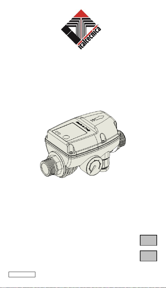
3.TECHNICAL DATA
Power Supply: ... ... ... ... ... ... .............115-230VAC ± 10% 50/60 Hz(Brio Green 230VAC)
Max current: ... ... ... ... ... ... ... ... ... ... ... ... ... ... ... ... ... ... ... ... ... ... ... 12 A
Cut-. 1 ÷ 3.5 bar
10 bar
W..°÷55°C
.5°C
°C
...................-10÷50°C
Type ( Ref. EN 60730-................1.C
..............III
Insulatio...III
Nm

4
4.DESCRIPTION
Brio 2000 is a device that enables pumps, with a minimum prevalence of 2 bar, to start
and stop automatically, with regard to a drop in pressure (opening of the taps) and to the
stopping of the flow through the system (closing of the taps) respectively.
Should the water supply be interrupted for any reason, Brio 2000 performs the important
function of stopping the pump, thus protecting it from harmful dry running.
It is also able to restart automatically, by means of an inbuilt timer, to check for the
eventual presence of water (this function is only available for versions with automatic reset
function).The inbuilt pressure gauge makes it easier to control the pressure within the
system; moreover any leaks in the system itself are easily identified.
It is strongly recommended that the water is free of any sediment. If in doubt, it
is necessary to install an appropriate sediment filter on the inlet side.
The device must not be installed inside wells or sealed enclosures, where
heavy condensation is likely to form.
Both Brio 2000 and the pump itself must be protected against freezing during
cold weather spells.
5.PARTS AND COMPONENTS
Fig.01 shows the major components:
6.OPERATION
The appliance activates the pump for about 15 seconds when it is powered. The pump
starts every time it senses a pressure drop within the system, for example when a tap is
opened.
Unlike traditional water system equipped with pressure switch and pressure tank, it is the
minimum flow that determines when the pump should stop, rather than the cut-out
pressure. The device delays the pump from stopping for a further 7 15 seconds, thus
reducing pump cycling in low flow conditions.
7. INSTALLATION
7.a HYDRAULIC CONNECTIONS
Brio 2000 can be installed either in a vertical or a horizontal position, anywhere between
the pump outlet and the first outlet (tap). Care must be taken to ensure that the direction of
the arrow on the cover is in the same direction of the flow of the fluid within the pipes (fig.
05). All hydraulic connections must be properly tightened. An adequate pressure reducing
unit must be fitted on the delivery port of any pump exceeding 10 bar working pressure.
CAUTION: With the exception of submersible pumps, installing a non-return
valve between the pump outlet and the Brio 2000 inlet may adversely affect
pump operation. (The pump may fail to stop)
If it is necessary to install a non-return valve, this must be mounted at least 3
meters away from the device (fig. 04).
a
Inlet connection
f
Pressure gauge
b
Outlet connection
g
Supply terminals
c
Mains indicator
h
Load terminals (pump)
d
Fault indicator (dry running)
i
Cut-in pressure adjustment screw
e
Reset button

5
In the case of very high flow rates, the Brio 2000 device can be installed in a "by-pass"
mode, in parallel with a non-return valve placed on the main outlet, as shown in Fig. 06, to
reduce pressure drop.
7. b ELECTRICAL CONNECTIONS
Note: All electrical connections should be carried out by qualified personnel only, as shown
in Fig. 3.
In the case of pumps with power exceeding 500 W and an ambient temperature greater
than 25° C, heat-resistant cables (resistant to at least 105°C) must be used. Use only the
terminals supplied with the device.
In the version in which the connecting cable is included, simply connect the power plug of
the pump to the electrical socket and the Brio 2000
outlet. Note: the units supplied with 1 mm2cables is suitable for maximum loads up to 10A.
For higher loads the supplied electrical cables must be replaced (by qualified personnel),
by at least 1.5 mm2cable.
The pump connected to Brio 2000 must be adequately protected against
current overloads.
8. CUT-IN PRESSURE ADJUSTMENT
CAUTION: Turning the adjustment screw will not alter the maximum pressure
delivered by the pump!
The pressure is factory pre-set at 1.5 bar, which is optimal for most applications. Different
working pressures may be obtained by adjusting the screw on the inner flange, which is
marked by the symbols + and -.
You may need to change the factory-adjusted pressure settings:
1) If the tap situated at the highest point is more than 15 metres above the Brio 2000 (fig.
05 Hmax: 30 mt)
2) For increased load, i.e. when the load pressure is added to the pump pressure (max. 10
bar).
CAUTION: It is important that the MAXIMUM PRESSURE of the PUMP is at
LEAST 1.0 BAR HIGHER THAN the cut-in pressure set ON THE BRIO 2000
device.
9. COMMISSIONING
CAUTION: If the water level happens to be below the level at which the pump is
installed (negative head), it is imperative to use a suction hose complete with foot
valve to prevent water from draining back into the well.
Before switching on, make sure that both the suction pipe and the pump are primed. Start
the pump by switching on the Brio 2000 device. As soon as the pump stops running, open
the tap positioned at the highest point within the system.
If there is a steady flow from the tap, and the pump runs uninterruptedly, the
commissioning procedure has been successful. If there is no continuous flow, try to run the
pump for a short while by holding down the RESET button. If the problem persists,
disconnect the Brio 2000 device and repeat the whole procedure.

6
10. PROTECTION AGAINST DRY RUNNING
If the pump stops running due to lack of water, the Red FAILURE light goes on. To reset
the system, press the RESET button after confirming the presence of water on the suction
side or temporarily disconnect the power supply
11. AUTOMATIC RESET
Should the pump stop running because of lack of water, the versions with automatic reset
(optional) begin to restart automatically at pre-set intervals of 15, 30 or 60 minutes,
depending on the model. This operation mode is indicated by the rapid flashing of the red
indicator light. This process is repeated until either there is new water available on the
suction side of the pump or else, the pump has reached the maximum number of pre-set
retries (2, 4 or 8 depending on the model). Should this limit be exceeded, the red indicator
light remains switched on. To reset the system, you must press the RESET button after
verifying the presence of water on the suction side.
12. MAINTENANCE
The device has been designed to provide maximum performance without the need for
special maintenance during its operational lifespan.
During extended periods of inactivity, particularly during the winter season, the device
should be completaly drained of water, in order to prevent it from being damage.
13. TROUBLESHOOTING
PROBLEM
POSSIBLE CAUSE
SOLUTION
1. The pump does not
deliver any liquid
1. The Fluomac was mounted
the other way round
2. The priming process was not
implemented correctly
3. The suction hose is not
properly immersed in the liquid
1. Check the installation of
the device and correct if
necessary
2. Press and hold the RESET
button until the flow is regular
3. Check that the suction
hose is well immersed in
water
2. The pump does not
reach the desired
pressure
1. There are leaks in the
system
2. The hose or suction filters
are clogged
3. The foot valve is blocked
1. Check for leaks
2. Remove any clogging
3. Replace the foot valve
3. The device stops
the pump from
running even in
presence of water
1. The pressure is set too high
protection may prevent the
pump from running
1. Decrease the pressure until
the problem is resolved.
Contact a professional
installer.
2. Check the pump
4. The pump does not
start when a tap is
opened
1. The pressure is set too low
1. Increase the pressure until
the problem is resolved.
Contact a professional
installer
5. The pump starts
and stops frequently
1. There are leaks in the
system
2. The flow of water from the
tap is too low
1. Check for any leaks and
resolve as necessary
2. Contact technical support

7
6. The pump keeps
running and does not
stop
1. The flow switch of the Brio
is dirty
2. There are significant leaks
within the system
3. A check valve has been
installed before or after the
Brio 2000 device
1. Check the device
2. Check the plumbing
system
3. Remove any valves from
the system
The crossed-out wheelie bin symbol shown above indicates that, in respect of the
environment, the device must not be disposed of as public waste at the end of its
lifetime. Dispose of the device and packaging material in compliance with local
legislation.

8
.
:
. . IDN = 30MA.
: . .
2.
24 . /. / . .