Italtherm 30 K User manual

CITY CLASS
use
installation
adjustment
maintenance
Handbook
instruction
ENG
25 k
30 k
35 k
Green Heating Technology
IMPORTANT! Install the gasket includ-
ed in the documents bag, on the intake/
outlet ange, as shown on page 21.

Green Heating Technology
2
Table of Content
Safety warnings 3
Safety warnings symbols legend � � � � � � � � � � � � 4
References to Laws and Norms � � � � � � � � � � � � � 4
Personnel in charge of installaon � � � � � � � � � � � � � 4
Installaon, use and maintenance � � � � � � � � � � � � � 4
User warnings � � � � � � � � � � � � � � � � � � � � � � � � � � � 5
Important � � � � � � � � � � � � � � � � � � � � � � � � � � � � � � � � � 5
First starng up and Use � � � � � � � � � � � � � � � � � � � � � 5
Installaon, rst starng up, maintenance and
servicing � � � � � � � � � � � � � � � � � � � � � � � � � � � � � � � � � 6
Appliance booklet or central plant booklet � � � � � � 6
Combuson checking � � � � � � � � � � � � � � � � � � � � � � � � 6
Boiler operaon and servicing � � � � � � � � � � � � � � � � � 6
User guide 7
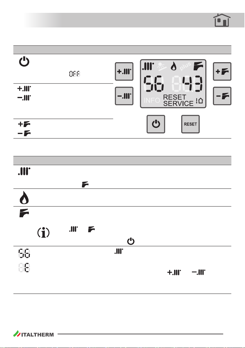
The front control panel � � � � � � � � � � � � � � � � � � � � 7
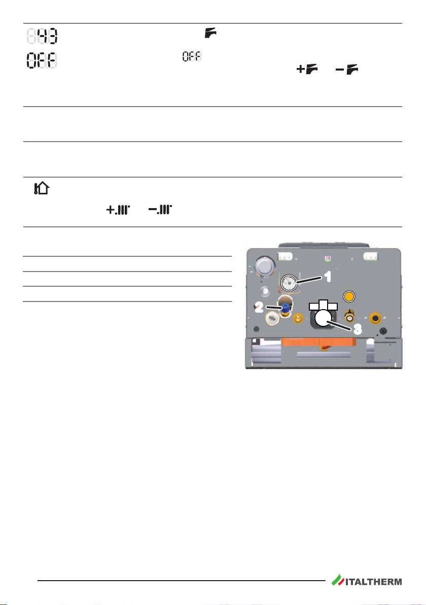
Commands on the lower side � � � � � � � � � � � � � � 8
Commands outside the boiler � � � � � � � � � � � � � � 8
Typical use � � � � � � � � � � � � � � � � � � � � � � � � � � � � � � 9
Preliminary operaons � � � � � � � � � � � � � � � � � � � � � � � 9
Boiler acvaon � � � � � � � � � � � � � � � � � � � � � � � � � � � � 9
Temperature adjustment � � � � � � � � � � � � � � � � � � � � � 9
Incidental malfunconing � � � � � � � � � � � � � � � � 10
The burner doesn’t turn on � � � � � � � � � � � � � � � � � � 10
Shortage of domesc hot water producon � � � � 10
Boiler inacvity � � � � � � � � � � � � � � � � � � � � � � � � � 11
Safety shut o � � � � � � � � � � � � � � � � � � � � � � � � � � � � � 11
Stand-by mode with an-frost & an-locking
funcon � � � � � � � � � � � � � � � � � � � � � � � � � � � � � � � � 11
“Ambient An-Frost” Funcon � � � � � � � � � � � � � � � 12
Installaon 12
Law and regulaon prescripons for the
installer � � � � � � � � � � � � � � � � � � � � � � � � � � � � � 12
Dimensions and connecons � � � � � � � � � � � � � � 13
Pump capacity diagram � � � � � � � � � � � � � � � � � � 13
Warnings for the installaon of oponal kits
or special systems � � � � � � � � � � � � � � � � � � � � � 14
Floor heang system � � � � � � � � � � � � � � � � � � � � � � � 14
Specicaons for intake air � � � � � � � � � � � � � � � 14
Domesc water supply characteriscs � � � � � � 15
Protecon against freezing � � � � � � � � � � � � � � � 15
Outdoor installaon in a parally protected
place � � � � � � � � � � � � � � � � � � � � � � � � � � � � � � � � 15
Posioning and fastening � � � � � � � � � � � � � � � � � 16
Hydraulic system (DHW and heang) � � � � � � � 17
Advices and suggesons to avoid vibraons and
noises in the system � � � � � � � � � � � � � � � � � � � � � � 17
Cleaning and preservaon of the systems � � � � � � 17
Heang system � � � � � � � � � � � � � � � � � � � � � � � � � � � � 17
Condense drain � � � � � � � � � � � � � � � � � � � � � � � � � 18
Heang system lling and pressuring � � � � � � � 18
Gas connecon � � � � � � � � � � � � � � � � � � � � � � � � � 19
Electrical connecons � � � � � � � � � � � � � � � � � � � � 20
Flue systems � � � � � � � � � � � � � � � � � � � � � � � � � � � 21
Intake/outlet ange � � � � � � � � � � � � � � � � � � � � � � � � 21
Installaon of the ue intake/outlet ange
gasket � � � � � � � � � � � � � � � � � � � � � � � � � � � � � � � � � � 21
General indicaons � � � � � � � � � � � � � � � � � � � � � � � � � 21
Examples of installaon of intake and outlet
ducts � � � � � � � � � � � � � � � � � � � � � � � � � � � � � � � � � � � 23
Dimensioning the intake and outlet ducts � � � � � � 24
Flue system types � � � � � � � � � � � � � � � � � � � � � � � � � � 25
Allowed ue types � � � � � � � � � � � � � � � � � � � � � � � � � 26
Adjustment and Maintenance 27
First starng up � � � � � � � � � � � � � � � � � � � � � � � � � 27
Maintenance operaons � � � � � � � � � � � � � � � � � 28
Access to the inside of the boiler � � � � � � � � � � 29
Venng the primary exchanger � � � � � � � � � � � � 30
Combuson group cleaning and check � � � � � � 30
PCB parameters sengs (technician menu) � � 31
Main boiler parameters (PC) � � � � � � � � � � � � � � � � � 32
Combuson test � � � � � � � � � � � � � � � � � � � � � � � � 35
Power adjustment tables � � � � � � � � � � � � � � � � � 36
Max heang power adjustment � � � � � � � � � � � 37
Combuson calibraon � � � � � � � � � � � � � � � � � � 37
Accessing the main board � � � � � � � � � � � � � � � � 38
Main board replacement � � � � � � � � � � � � � � � � � 38
Board conguraon codes � � � � � � � � � � � � � � � � � � � 38
Gas conversion � � � � � � � � � � � � � � � � � � � � � � � � � 39
Draining the heang system � � � � � � � � � � � � � � 40
Pump sengs � � � � � � � � � � � � � � � � � � � � � � � � � � 40
Alarms - boiler block � � � � � � � � � � � � � � � � � � � � � 41
Warnings for servicing � � � � � � � � � � � � � � � � � � � 46
Technical data � � � � � � � � � � � � � � � � � � � � � � � � � � 47
Boiler internal components � � � � � � � � � � � � � � � 49
Electrical diagram � � � � � � � � � � � � � � � � � � � � � � � 50
Hydraulic diagram � � � � � � � � � � � � � � � � � � � � � � � 51
Addendum 52
Outdoor Sensor Kit � � � � � � � � � � � � � � � � � � � � � � 52
Installaon and seng � � � � � � � � � � � � � � � � � � � � � � 52
Outdoor Sensor kit and Remote Control � � � � � � � 52
Remote Control Kit � � � � � � � � � � � � � � � � � � � � � � 53

Green Heating Technology 3
Safety warnings
This instrucons manual is an essenal and complementary part of the product and it is supplied to-
gether with the boiler�
Carefully read the manual, achieving all important informaon for a safe installaon, use and
servicing�
fCarefully keep the manual, together with the documentaon of all the accessories of the boiler and
of the system, for any further consultaon you may need.
fThe installaon must be carried out by a qualied technician, in accordance with manufacturer in-
strucons and with the relevant requirements of the current issue.
fCarbon monoxide (CO) danger: the CO is a no-smelling and no-colour gas. When a forced draught
boiler with air intake from the room (appliance type B2) is installed, permanent venlaon of the
installaon room is mandatory and extremely important. Venlaon must be made and sized in
compliance with Laws and Rules in force. Whatever manumission, closing or neutralizaon of the
permanent venlaon could lead to very serious consequences to people in the rooms, as intoxica-
on by CO, permanent damage and death. Besides, the CO and O2mix can be explosive�
fA qualied technician is a person with a specic technical competence in the eld of the heang
appliances for domesc use and domesc hot water producon, in compliance with Laws and Rules
in force�
fThe operaons that the user can do are only and exclusively the ones contained in the "USER GUIDE"
secon.
fThe manufacturer has no contractual and extra-contractual responsibility for any damage arising
from wrong installaon, wrong use and non-observance of current laws and instrucons given by
the manufacturer himself.
fImportant: this gas boiler is used to heat the water at a temperature lower than the boiling one, at
atmospheric pressure; it must be connected to an heang system and/or to a domesc hot water
system, in accordance with its features and power.
fPacking items (cartons, nails, plasc bags and so on) must not be le within children easy reach, as
they are potenally dangerous.
fBefore any cleaning or servicing operaon, disconnect the boiler from the mains electrical supply by
means of the main electrical switch and stop the gas supply by means of the suitable cock.
fIn case of fault and/or bad operaon of the appliance, disconnect it immediately and do not try to
repair it by yourselves.
fBoiler servicing and repair must be carried out exclusively by qualied technicians, which will use
original spare parts. Strictly observe the above requirement, avoiding any risk of compromising the
appliance safety�
fIf the appliance should be denively dismissed, remove or cut o any potenal dangerous item.
fWhen transferring the appliance (e.g. leaving it installed aer a removal or a sale of the building),
make always sure that the instrucons manual is close to the boiler for the future use of new owners
and/or installers�
fThis appliance must be used for its clearly recommended ulizaon only. Any other ulizaon must
be considered dangerous and incorrect.
fIt is strictly forbidden to use the appliance for dierent purposes than the specied ones.
fThis appliance must be installed exclusively to wall�

Green Heating Technology
4
Safety warnings symbols legend
Generic safety
warning
Electrical danger
(fulguraon)
Physical danger
(personal damage)
Thermal danger
(burns)
General warning or advice to avoid material damage
or to achieve improvements
References to Laws and Norms
All references to laws and laws contained in this handbook, as well as all installaon, maintenance and
use prescripons and the relevant pictures, are relevant to European and/or Italian regulaon.
All laws and norms in force in the territory where the installaon takes place prevail on the indica-
ons contained in this handbook, that are inconsistent with them.
All the references to norms and naonal laws menoned in this handbook are indicave as
laws and norms are subject to issues and integraons by the authories in charge. Also comply
to eventual local norms and laws (not menoned in this handbook) in force in the territory
where the installaon takes place.
Personnel in charge of installaon
Always comply with naonal and/or local regulaon about WORK SAFETY of Personnel in
charge of installaon.
Always proceed with cauon when handling the boiler and carrying out installaon/mainte-
nance work as metal parts may cause injuries such as cuts and abrasions. Wear personal protec-
on devices (especially gloves) while doing the above menoned operaons
Installaon, use and maintenance
Always comply with naonal and/or local regulaon about BOILER INSTALLATION.

Green Heating Technology 5
User warnings
Important
In case of gas smell:
1 - do not press electrical switches, use the telephone or other objects that can provoke
sparks;
2 - open immediately the windows and the doors in order to cleanse the room air;
3 - close the gas supply taps;
4 - call a qualied technician.
Do not obstruct the venlaon openings of the gas boiler room, in order to avoid possible
dangerous situaons as the creaon of poisonous or explosive mixtures.
First starng up and Use
The rst starng up and the maintenance of the boiler must be performed by a professionally
qualied sta (for example the installer or the Service Centres authorized by ITALTHERM)
The laer will check that:
fthe label technical data of the gas boiler correspond to those of the gas available;
fthe main burner regulaon is compable with the gas boiler output;
fthe chimney works correctly, expelling the combuson products;
fthe air supply and the combuson products evacuaon work correctly, in accordance with the re-
quirements in force;
fthe condions for a correct venlaon are guaranteed, also when the gas boiler is located inside a
closed space (with suitable caracteriscs).
This boiler is designed and prepared to be supplied with Natural Gas G20 (Methane). It can
be set, just by means of electronic sengs, but always by a qualied technician, to operate
with Commercial Propane G31. It must never be used with butane gas G30 (that can be present,
pure or mixed with Propane G31, in the portable gas boles for cookers).
The User must not touch sealed items nor break the seals. Only specialized technicians and the
ocial technical service can break the seals of sealed items.
The boiler is ed with safety devices that block operaon the case of problems with the boiler
or related systems. These devices must never be disabled: if a device intervenes frequently,
have a qualied technician located the cause, even in systems to which the boiler is connected,
and in the ue intake/outlet system that must be ecient and made according to the laws in
force (see examples in paragraph "Flue systems" on page 21). If a boiler component has failed,
you must only use original replacement parts
When the boiler is o for a long period see the Paragraph "Boiler inacvity" on page 11 for
the necessary precauons about the electrical supply, the gas supply and the protecon against
freezing.
Do not touch the heated surfaces of the boiler, as the doors, the ue, the chimney pipe, etc.,
also aer the boiler operaon because, for a certain me, these surfaces are overheated. Any
contact with them can cause dangerous scalds. It is then forbidden to let children or inexperi-
enced people be close to the boiler, during its operaon.

Green Heating Technology
6
fDo not expose the wall hung gas boiler to water or other liquids sprinklings, or to vapours directly
coming from gas cookers/hobs�
fDo not obstruct the air intake or ue outlet terminals, even momentarily or parally.
fDo not put any object on the gas boiler and don't leave any ammable liquid or solid materials, (e.g.
paper, clothes, plasc, polystyrene) in its proximity.
fThis appliance is not intended for use by persons (including children) with reduced physical, sensory
or mental capabilies, or lack of experience and knowledge, unless they have been given supervi-
sion or instrucon concerning use of the appliance by a person responsible for their safety. Children
should be supervised to ensure that they do not play with the appliance.
fIf the gas boiler is going to be denively unused, call a qualied technician to carry out all required
operaons, checking in parcular disconnecon of gas, water and electrical supplies.
fOnly for those models that draw directly from the installaon room (type B appliances installed in-
door): the installaon of aspirators, replaces or similar appliances in the room where the type B ap-
pliance is installed (and in adjacent rooms in case of indirect venlaon) is prohibited except in cases
foreseen by rules in force and anyway the installaon must be made in compliance with all specic
safety measures menoned in the rules and laws in force, even in case of modicaons or addions.
Installaon, rst starng up, maintenance and servicing
All operaons for installaon, rst starng up, maintenance, servicing and gas conversion must be car-
ried out by qualied technicians, in accordance with the Norms and Laws in force.
Maintenance operaons must be carried out in compliance with the manufacturer prescripons, and in
compliance with the laws and rules presently in force for what is not menoned in this handbook; we
advice to perform them at least once a year to maintain the boiler’s performance.
Appliance booklet or central plant booklet
All appliances must have an appliance booklet (for outputs less or equal 35 kW) or a central plant book-
let (for outputs more than 35 kW). All maintenance and servicing operaons and combuson checks
must be wrien on the booklet, together with the name of the person responsible for servicing.
Combuson checking
Combuson checking consists of a control of the boiler eciency. Boilers that, aer the checking, will
have eciency rates lower than the ones required and not changeable with suitable adjustments (that
must be performed by qualied technicians), must be replaced.
Boiler operaon and servicing
The user (owner or tenant of the at where the boiler is installed) or the administrator of the block of
ats (in case of a central heang system) are responsible for the appliance operaon and servicing; they
can both transfer the responsibility of the servicing and eventually of the operaon to another person,
which must be a qualied technician as indicated by the Laws. Even if the user or the administrator de-
cide to assume personally this responsibility, ordinary servicing of the warm air heater and combuson
checks must be anyway carried out by a qualied technician

Green Heating Technology 7
User guide
The front control panel
Pushbuons
Stand-by / Funconing mode
At every press, the boiler switches
its mode from to summer or
winter mode�
00314 00
CH seng
To set the CH system temperature.
If the Outdoor Sensor Kit was in-
stalled, see also "Outdoor Sensor
Kit" on page 52.
DHW seng
To set the DHW temperature.
RESET Press to reset the boiler in case of breakdown�
See further details in "Alarms - boiler block" on page 41.
Display - symbols enabled in this model and their descripon
CH – winter mode indicaon
If ashing, it means that the boiler is funconing in CH mode. See also the remark in the
descrion of symbol .
Burner ON
It indicates the presence of the ame in the burner.
DHW mode indicaon
If ashing, it means that the boiler is funconing to produce hot water.
If both and symbols ash at the same me, a Technician-reserved funcon
has been acvated. In this case, turn immediately the boiler o - and then turn it
on again - by means of the buon �
Two digit display under the symbol
Normally, it displays the CH ow temperature, i.e the temperature of the liquid on boiler's
outlet that is sent to the CH system.
During the CH temperature seng (by pressing the buons and ), it shows
the temperature value changing; in case of alarm it displays "E"; during the seng
(reserved to the Technician) it displays the chosen parameter ID number (see "PCB param-
eters sengs (technician menu)" on page 31).

Green Heating Technology
8
Three digit display under the symbol
Normally, it displays the temperature of the hot water on boiler's outlet. When the boiler
is in stand-by mode, it displays .
During the DHW temperature seng (by pressing the buons and ), it shows
the temperature value changing; in case of alarm it displays the ID number of the alarm
(see "Alarms - boiler block" on page 41); during the seng (reserved to the Techni-
cian) it displays the value of the chosen parameter�
RESET It appears when the boiler is locked or anyway is present an error that the user could man-
age. See "Alarms - boiler block" on page 41 to idenfy the problem and the relevant
acons to be carried out.
SERVICE It appears when the boiler has detected an error (mainly a fault) that has to be managed
by the Technician. The User can anyway see "Alarms - boiler block" on page 41 to get
informaon about and the eventual acons to be carried out.
It informs that the outdoor probe (accessories) is installed.
Note: In this case the CH system temperature is automacally set and so the use of but-
tons and is dierent from the standard way: for deeper detailsrely on
kit instrucon and see "Outdoor Sensor Kit" on page 52.
Commands on the lower side
1System pressure gauge
2System lling and pressure restoring cock
3GAS cock
Commands outside the boiler
Externally the boiler, suitably posioned in the build-
ing (generally by the installer or by the electrician), two
devices that the user should access to, are present. The
presence and the characteriscs of these devices are pre-
scribed by the regulaon in force.
Two-pole switch: it is located usually close to the boiler and it's for electrically insulang the boiler
itself from the domesc mains power supply network. It is useful to disconnect the boiler from the
electrical supply, e.g. during inacvity periods (see "Safety shut o" on page 11) or in some cases
of alarm (see "Alarms - boiler block" on page 41).
Room thermostat: it commands electrically the boiler to acvate or deacvate the heang system, in
order to keep the room temperature (detected by a sensor) within a value set by the user, Regula-
on in force prescribe its posioning, the temperature limits within the user can adjust it and the
periods of heang.
Remark: an oponal, original Remote Control kit is available (see "Remote Control Kit" on page 53
for informaon) or a cung-edge chronotermostat kit featuring weekly programming of various
temperature levels and other special funcons. Also wireless and GSM controlled versions are
available.
00315_00
2
3
1

Green Heating Technology 9
Typical use
Preliminary operaons
fBe sure the gas cock 3 is opened�
fBe sure the boiler is electrically powered and set in OFF: only has to be displayed on the screen�
fMake sure, by the gauge 1that the cold-system temperature is always within 0.5 and 1.5 Bar (op-
mal: 1÷1.5 Bar). When the pressure drops below 0.5 Bar, the boiler stops working. In this case, open
the system lling cock 2 up to obtain, on the gauge, a value between 1.0 and 1.5 Bar�
The system pressure raises with the temperature: a too high inial cold-system pressure could
lead to water drain from the 3 Bar safety valve aer the system heang-up.
Boiler acvaon
fPress the buon :
• once to set the boiler in summer mode only (DHW only). Summer mode is recognizable by the
only symbol presence on the display and not by the symbol presence ;
•pressing twice to set the boiler in winter mode for making the boiler working both for CH and
DHW. Winter mode is recognizable by the both symbols presence and on the display;
• at each press of the buon , the boiler cyclically switches from OFF to summer and to
winter + mode�
fOpening a DHW tap, the burner res up, and later then DHW is available.
fOn winter mode + , when room thermostat demands for heang, the burner res up and
thanks to the water ow the heang get transferred . In case of contemporary demand of both DHW
and CH, the DHW demand has the priority ll the demand nish. Usually, as DHW does not last for
long, this priority does not aect the CH eciency in the system.
Temperature adjustment
Note: correct adjustment leads to creang the condions for energy saving.
Note: if a Low Temperature Kit or an Outdoor Probe Kit are installed, refer to the relevant documen-
taon for what concerns the heang system temperature adjustment.
Note: don't make confusion between the heang system temperature here described, with the
temperature of the room set on the Room Thermostat.
fHeang system adjustment: by using the buons and , the seng of the heang
system temperature is made (the value, during the adjustment, is shown on the display under the
symbol ). Generally, in the deep cold season and/or with poor building thermal insulaon (or
if you noce that the burner stays on for a long me, but the room temperature rises too slowly)
prefer higher sengs. On the contrary, if you noce that the room temperature exceeds too much,
for thermal inera, the value set on the room temperature, it's appropriate to decrease the system
temperature. When the oponal Outdoor Temperature Probe Kit is installed, the system tempera-
ture is automacally managed and the use of the buons and is dierent: for details,
see also "Outdoor Sensor Kit" on page 52.
fDomesc hot water adjustment: the buons and set the temperature of the hot water
produced by the boiler (the value, during the adjustment, is shown on the display under the sym-
bol ). On this type of boiler, we suggest to set it in such a way to have a comfortable hot water
temperature by drawing only hot water or eventually by mixing it with a lile cold water. Avoid

Green Heating Technology
10
maximum values if not strictly needed, that will force to mix the hot water with bigger quanes of
cold water. Consider that, because of the dispersions along the pipings, a certain me is needed to
have a stable water temperature on the cock outlet, therefore the best temperature evaluaon is
achieved during a bath or a shower.
Incidental malfunconing
Avoid performing personally any intervenon that are job of the technician, for example the
ones on the electrical circuits, on hydraulic system or on the gas system, and whatever other
operaon that's not menoned in this "User Guide" secon and expressly allowed to the User.
Always address yourselves to qualied personnel.
Boilers must be always equipped with original accessories only.
ITALTHERM Srl is not responsible for damages caused by the incorrect, wrong or unreasonable
use of not original materials.
The burner doesn’t turn on
fif the room thermostat (or programmable room thermostat, or similar) is installed, check that it is
really requiring the room heang;
fbe sure the boiler is set on winter + or summer mode (not in OFF). The reference symbols
must be shown on the display (see "The front control panel" on page 7);
fin case the display shows or , or in case the boiler seems to be working in an
inappropriate way, see "Alarms - boiler block" on page 41;
fcheck on the gauge that the boiler pressure is correct (1÷1.5 Bar in a cold state) or at least not below
0.5 Bar�
Shortage of domesc hot water producon
fcheck the DHW temperature is not set on a too low value: if so, adjust it (see "Temperature adjust-
ment" on page 9);
fcall a qualied technician to check gas valve regulaon;
fcall a qualied technician to check, and eventually clean, the DHW exchanger.
Remark: where the water hardness value is too high, it is suggested the installaon of a soen-
ing device, in order to prevent the limestone precipitaon; this operaon avoids a frequent
cleaning of the coil�

Green Heating Technology 11
Boiler inacvity
The eects of the periods of inacvity can be relevant in parcular situaons such as in ats used only
for some months per year, most of all in cold places.
The user will have to decide to put the boiler in the SAFETY SHUT OFF state disconnecng all the sup-
plies, or to leave it on OFF mode (but electrically supplied) in order to let the An Frost Funcon work�
When there is the possibility of freezing it is convenient to chose between the advantages and the dis-
advantages of the SAFETY SHUT OFF and of the Stand By/An Freezing Way.
Safety shut o
fTurn o the general switch on the Electrical Supply Line of the Boiler;
fClose the Gas Tap;
When it is expected that the temperature is going to decrease under 0°C, call a technician to do
the following:
• Fill the system with an an-freezing soluon (unless the system was already lled with said solu-
on) otherwise it must be completely emped. Noce that if it had been necessary to restore
the pressure (because of possible loss) in an heang system already lled with an An freezing
soluon, the concentraon of the soluon could have decreased and it could not guarantee the
An freezing Protecon.
• Let the condense collector syphon be emped unscrewing its inferior cap.
• completely empty the hot and cold sanitary water system, including the sanitary circuit and the
boiler’s sanitary exchanger.
Remark: the boiler is equipped with a system which protects the main components from the excep-
onal cases of mechanical lock, due to the inacvity in presence of water and scale. The an-
locking funcon can’t work in Safety shut o mode, because of the lack of electrical supply.
Before re-igning the boiler, have a technician check that the pump is not blocked due to inac-
vity (for the technician: unscrew the plug in the centre of the cap to access the rotor sha and
turn it with a screwdriver or other suitable tool).
Stand-by mode with an-frost & an-locking funcon
When the boiler is le in OFF mode during a period of inacvity, it will be protected against freezing by
several funcons provided in the electronic controller, which heat the parts involved when the tempera-
ture falls below factory set values.
The an-frost heang is accomplished by turning on the burner and pump.
In addion, when the boiler is in stand-by, it periodically acvates the main internal components to
avoid rare cases of blockage due to inacvity in the presence of water and lime. This can also occur
when the boiler is locked (red lamp on) provided that the system pressure is correct.
In order for these systems to be acve:
• the boiler must be receiving gas and electricity;
• boiler must be le on OFF mode ( shown on the display);
• system pressure must be correct (1÷1.5 bar in a cold state, minimum 0.5 bar)
In case of gas supply failure, or if the boiler locks for other reasons (the display shows

Green Heating Technology
12
or ) the burner won’t turn on. Nevertheless, any me it is possible, the pump will work,
making the water circulate in the system and reducing in this way the possibility of freezing.
ATTENTION: the an-frost protecons cannot intervene in the absence of electricity. If you an-
cipate this possibility, we recommend you add a good brand of an-freeze to the heang sys-
tem, following the producer’s instrucons.
We recommend to ask directly the installer/technician about the type of anfreeze product
put in the heang system during installaon.
When the power comes back on, the boiler will check the temperature measured by the two
probes and, if it suspects freezing veried by a parcular automac control cycle, alarm 39 will
be triggered. For more details, see the relave descripon in the paragraph "Alarms - boiler
block" on page 41.
We recommend that you completely empty the hot and cold sanitary water system, including
the sanitary circuit and the boiler’s sanitary exchanger. The an-frost funcon does not protect
the sanitary circuit outside the boiler.
“Ambient An-Frost” Funcon
Note: if you want to use the “Ambient An-Frost” funcon that is oen available in common room
thermostats or chronothermostats, it is necessary to leave the boiler in Winter + mode
and NOT in mode.
The “Ambient An-Frost” funcon does not protect the sanitary circuit outside the boiler and,
especially, in areas where the heang system doesn’t reach. For this reason, we recommend
that you empty the cold and hot sanitary water from the parts of the system that are at risk of
freezing.
Installaon
Law and regulaon prescripons for the installer
Always comply with naonal and/or local regulaon about BOILER INSTALLATION.
Always comply with naonal and/or local regulaon about WORK SAFETY of Personnel in
charge of installaon.
Characteriscs of the room: as this boiler has an heat output lower than 35 kW (about 30000 Kcal/h),
it is not required to install the appliance in a dedicated room, provided that the room complies with
the regulaon in force and that all installaon rules assuring a safe and regular gas boiler operaon,
are strictly respected�
Permanent venlaon of the installaon room is mandatory and extremely important when
a boiler with air draught from the installaon room (B… appliance type) is installed. Venlaon
must be made and sized in compliance with Laws and Rules in force.
Presence of other appliances: the presence of other appliances (especially if they interfere with the
boiler draught) can be forbidden by the regulaon in force or can require modicaons (e.g. the
enlargement of the venlaon opening or the making of new ones).
Instrucng the user: at the end of the installaon, the installer must:
• explain the operaon of the boiler and its safety devices to the user;
• give this user this booklet and the documentaon within his/her competence, duly lled in where
required.

Green Heating Technology 13
Dimensions and connecons
50
45
L
TA
RMCGF
CF
G R
M G R
C F
2
1
3
4
M
190210
130
192
77
400 300
7279
10
9
7070 65 65 65 657070 65 65 65 65 120
SC
23÷43 23÷43
700
TA / L
SC
00319 00
Legend:
1 Flue outlet
2 Air intake for coaxial system
3 Air intake for split-pipe system
4 preset for an accessory not foreseen on
this model; don't use as air intake!
M System ow (¾”)
C DHW outlet (½”)
G Gas: connecon on the boiler ¾”;
on the wall, using the oponal
original ng kit ½”
F Fresh water inlet (½”)
R System return (¾”)
TA/L Indicave posion for electrical
power supply and room
thermostat wirings
TA Room thermostat wiring
L Electrical power supply wiring
SC Indicave posion for the
condensate drain
front view -
hydraulic connecons
on the wall
(with oponal ng kit)
see also page 16
upper view
front view -
hydraulic connecons
on the boiler
le side view -
hydraulic connec-
ons on the boiler
Pump capacity diagram
See also "Pump sengs" on page 40.
0
1
2
3
4
5
6
0200 400 1000 1200600 800 1400 1600
00362
A 01
pressure (m H2O)
water ow (l/h)
mod. 25K
speed 3 - 2 of the pump
The graph is referred
to the capacity available
to the system.

Green Heating Technology
14
0
1
2
3
4
5
6
0200 400 1000 1200600 800 1400 1600
00362
B 01
pressure (m H2O)
water ow (l/h)
mod. 30K
speed 3 - 2 of the pump
The graph is referred
to the capacity available
to the system.
0
1
2
3
4
5
6
0200 400 1000 1200600 800 1400 1600
00362
C 01
pressure (m H2O)
water ow (l/h)
mod. 35K
speed 3 - 2 of the pump
The graph is referred
to the capacity available
to the system.
Warnings for the installaon of oponal kits or special systems
Floor heang system
The safety thermostat(s) that protects the oor against overheang (that could damage the
cladding, the structure or the system itself) must be installed on the ow starng end of the
serpenne embedded in the oor itself. It should not installed on the system ow pipe in prox-
imity of the boiler, otherwise frequent and unjused boiler locks, caused by its triggering, are
possible�
Specicaons for intake air
Air must be withdrawn from places free of pollutant (like uorine, chlorine, sulfur, ammonia, alkaline or
similar agents). In the event of installaon of the boiler in atmospheres with not negligible presence of
aggressive chemical substances (e.g. hairdressing salons, laundries) we recommend to foresee the air
intake from outdoor, choosing the type C installaon.

Green Heating Technology 15
Domesc water supply characteriscs
The cold water inlet pressure must be lower than 6 Bar. Besides, for an opmal boiler funconing, wa-
ter pressure should be more than 1 Bar. A lower pressure could make dicult to restore correctly the
pressure the heang system, and reduce the ow of hot water available from the boiler.
In case of higher pressure it is indispensable to install a PRESSURE REDUCER upstream the
boiler�
The cleaning frequency of the DHW heat exchanger depends on the water supply hardness. If the wa-
ter hardness is more than 25° fr it’s required to install a soener to bring the hardness below that value.
Besides, the presence of solid residuals or impuries in the water (for example in case of new systems)
could compromise the correct funconing of the boiler. For DHW producon systems, the regulaon in
force prescribes a safety lter to protect the systems.
The condensing burner/exchanger assembly requires parcular characteriscs for the heang
system liquid, more restricve than the ones of the inlet domesc water. See the "Heang" sec-
on of the table "Technical data" on page 47.
Protecon against freezing
Thanks to its anfreeze system, inner components could never reach a temperature lower than 5°C. This
system is acvated when the boiler is supplied by the electrical and gas lines, provided that the pressure
in the heang system is correct.
If some part(s) of the system external to the boiler could be subject to freezing risk, it is advis-
able to ll the heang circuit with, instead of water, an anfreeze liquid specic for heang
systems, propylenic glycol based, following the instrucons of its manufacturer. Pay aenon
to the correct product concentraon: adding those substances to the heang water in incorrect
dose could lead to the deformaon of the seals and cause unusual noises during operaon.
ITALTHERM S.r.l. will not be held responsible for consequent damages.
Instruct the User about the anfreeze funcon of the boiler and about the anfreeze product
added in the heang system.
Outdoor installaon in a parally protected place
This type of forced draught condensing boiler can
be installed outdoor, but only in parally protect-
ed places�
The boiler minimum and maximum working tem-
peratures are menoned in the paragraph "Tech-
nical data" on page 47 and on the boiler data
plate�
The materials used for the boiler installaon,
including the devices and/or the materials used
for thermal insulaon, should be so to maintain
their funconality within the temperature range
indicated on the data plate�
If the place where the boiler is located is converted from outdoor to indoor (e.g. veranda) it will
be necessary to verify the compliance of the new conguraon with the laws and rules in force,
and to make the modicaons required.
00004 00

Green Heating Technology
16
Posioning and fastening
Remark: A re-usable metal jig ( D in the gure) can be ordered separately,
so as to facilitate connecons and xing points posioning (when the
original connecon kit is used). If the metal jig and/or the original
connecon kit are not used, refer to the paragraph "Dimensions
and connecons" on page 13 for the posion of the connecons
directly on the boiler.
fLocate the exact posion of the boiler considering the sucient clear-
ances for maintenance and servicing: at least 50mm laterally and 300
mm on the lower side
fChoose the fastening/hooking opon among A or B, depending on the
xing devices used or already available if any (open hooks; wallplugs;
“stud” type with nut).
fIf the metal jig is used, hang it on the wall using the same xing devices
and the holes or slots A or B�
fFix up the connecons and all ducts for heang ow and return, cold wa-
ter, hot water, gas and electrical cables, predisposing them in the holes
of the metal jig or, as an alternave, respecng the measures
in the paragraph "Dimensions and connecons" on page 13.
The upper edge of boiler’s body, used as a reference in the para-
graph "Flue system types" on page 25, is represented by the
doed line C in the gure.
•model 35 K only: pull upwards and remove the plasc blocks
that hold the sides of the expansion vessel�
fRemove the jig (if used) and hang the boiler to the xing devices,
using the chosen holes or slots A or B�
fRemove the plasc caps placed to close the hydraulic connec-
ons on the boiler.
32.5
36
18
328
70
45 50
7065656565
9
18
36
335
400
32.5
35 11 14
40 30 15
727
A A
B B
C
D
A
B
C
00321 00
Heang
Flow (3/4”)
Hot Water
Outlet (1/2”)
Gas (1/2”)
Cold Water
Inlet (1/2”)
Heang
Return (3/4”)
Electrical
Power Supply
Room
Thermostat
00359 00

Green Heating Technology 17
fProceed with the hydraulic, gas, electrical and ue connecons following the instrucons and warn-
ings reported in the following paragraphs�
The connecons of the boiler are engineered to t plain couplings with screw ring, interposing
a plain gasket of suitable size and material, that ensure a reliable seal even without excessive
ghtening force. They are NOT suitable for hemp, teon tape or similar materials
Hydraulic system (DHW and heang)
Make sure that the hydraulic and heang systems ducts are not used as earth connecons of
the electrical system. They are absolutely NOT SUITABLE for such a use. Besides: they don't
guarantee the earth dispersion; in case of electrical fault they could generate a fulguraon risk;
there could take place galvanic currents in the pipings and consequent corrosion and hydraulic
leaks�
Advices and suggesons to avoid vibraons and noises in the system
fDo not use pipes with reduced diameters;
fDo not use bends with small radius and reducons of important secons.
Cleaning and preservaon of the systems
The eciency, the reliability and the safety of the boilers, as all generic thermal systems and compo-
nents, depend strictly on the features of the water that supply them and on their treatment.
A proper treatment of the water improves the protecon of the systems against corrosions (and there-
fore perforaons, noise, leaks, etc.) and limestone incrustaons that drascally reduce the eciency
of the thermal exchange (consider that 1 mm of limestone incrustaons reduces of 18% the thermal
exchange of the heang element on which it has been formed).
ITALTHERM guarantees its products only if the characteriscs of the water comply with UNI 8065, re-
ported also in laws on energy saving�
Thoroughly wash the heang system with water, before connecng the boiler. This will elimi-
nate residual like welding drops, slag, hemp, masc, mud, rust and other dirt from pipes and
radiators. Otherwise, these substances could enter the boiler and damage the internal compo-
nents (pump etc.).
fIn case of old or very dirty systems, to wash them use specic, proven eciency products, in the
suitable quanty and following the instrucons of its manufacturer.
fIf the water on boiler inlet is harder than 25° fr, it’s required to install a soener to bring the hardness
below that value, as required by the reference regulaon.
fFor oor system and generally all low temperature systems, the water treatment product must have
lming acon (protecon against corrosion and incrustaon) and acon against bacteria and algae.
Heang system
fConnect the safety evacuaon ducts of the boiler to an evacuaon funnel. If safety valves are not
connected to an evacuaon device, their intervenon could ood the room. The manufacturer can-
not be held responsible for any damage arising from that situaon.

Green Heating Technology
18
Condense drain
Insert the exible pipe of condense outlet inside the outlet funnel (or other inspectable connecon de-
vice) properly installed for this purpose, or in the outlet funnel of the safety valve, in case of the above
menoned outlet is able to receive the acid liquids of the condense as foreseen by the norms in force
in maer of condensing boilers.
Requirements for the condense drain system:
◦ It must be made in a way that doesn't allow the condense freezing or other blockages, and it
must not allow modicaons or obstrucons
◦ before the rst starng up of the appliance, ensure that the condense can be correctly drained
◦ if the intended use of the building unit foresaw the installaon of a condensate neutralizaon
system, make sure that you have the relevant instrucons for use, cleaning and maintenance
Heang system lling and pressuring
Once all system connecons have been carried out, proceed with system lling. This operaon should
be made with care, respecng the following steps:
fOpen the radiators venng devices;
fCheck that the plug of the automac air vent, incorporated in the boiler circulator, is unscrewed: if
not, unscrew it and leave it unscrewed, even aerwards, for normal operaon;
fIf it's required to ll the system with an-freeze soluon, do this operaon, then hermecally close
the connecon or the valve used to put the soluon in, to allow the pressurizaon.
fGradually open the lling cock 2 ;
fCheck the correct funconing of automac venng
devices, eventually installed;
fClose the radiators venng devices as soon as water
ows out of them;
fMake sure, by reading the pressure gauge 1, that
the pressure reaches the opmal value of 1.0 bar
(max 1.5 bar);
fClose the water lling cock 2 and bleed each radia-
tor again;
fRepeat the venng and pressurizaon operaons
unl the air is completely purged from the system.
00316_00
2
3
4
1

Green Heating Technology 19
Gas connecon
Due to various installaon possibilies, the gas cock 3 supplied with the original Connecons Kit has a
simple male Ø ½” connecon, facing the rear of the boiler. The gas pipe 4, upstream the gas cock 3, should
be supplied by the installer.
While connecng the gas inlet of the boiler to the gas supply piping, it is MANDATORY to
insert a PLAIN GASKET, whose dimensions and material must be adequate. Connecon is NOT
suitable for hemp, teon strip or similar materials. Because of the type of ng, the use of
those materials does not make the suitable seal with consequent gas leaks!
This boiler is designed and prepared to be supplied with Natural Gas G20 (Methane). It can be
set, just by means of electronic sengs, but always by a qualied technician, to operate with
Commercial Propane G31.
It must never be used with Butane gas G30 (that can be present, pure or mixed with Propane G31,
in the portable gas boles for cookers) therefore, if the boiler is prepared for operaon with
commercial Propane G31, we recommend to inform the supplier of the fuel, for example, by
applying a suitable warning on the gas tank or in its immediate vicinity, so that it is visible to
the employee when it is being relled.
Using Propane gas G31, it is absolutely necessary to install a pressure reducer upstream the
boiler. Failure to do this, the gas valve of the boiler will get damaged. The inlet gas pressure
must be compliant with the one specied in "Technical data" on page 47.
The gas connecon, as generally the boiler installaon, must be done by qualied personnel as
prescribed by the regulaon in force, because a faulty gas connecon could lead to re, explosion
and other very serious damages to persons, animals and objects. The manufacturer cannot be
held responsible for any damage arising from that situaon.
fVerify what follows:
• cleaning of all system gas pipes in order to avoid the presence of work residuals that could com-
promise the correct boiler funconing;
• gas line and ramp conformity with laws and rules currently in force;
• internal and external ghtness of the gas system and connecons;
• supply pipe must have a secon greater than or equal to the boiler one;
• supply gas must correspond to the one for which the boiler has been set: otherwise, it's manda-
tory to ask to qualied personnel to set the boiler for the correct gas type;
• an intercepon valve must be installed upstream the appliance.
fOpen the meter valve and purge the air that is inside the system pipes (including all the appliances).

Green Heating Technology
20
Electrical connecons
The link of the room thermostat works with a safety extra low voltage (SELV); connect it to
the voltage free contacts of the room thermostat/chronothermostat� On NO account must any
electrical voltage be applied to these terminals�
All low-voltage wirings (e.g. Room Thermostat or Chronothermostat for trade) must be kept
separate from power supply cables, as to avoid boiler malfunconing due to electrical noise. It
is advisable to use separate tubes for them.
During the connecon of cables from the boiler, make sure that them are not ght and make a
slack that allows the control panel to be fully lted.
The boiler must be connected to a 220÷240V - 50Hz electrical power supply. In any case, the power
supply voltage must be within the range –15% ... +10% from the nominal value (230V); otherwise it
may cause malfuncons or failures. It is necessary to respect the polaries L-N (Live L=brown; - Neu-
tral N=blue) - otherwise the boiler may not work - and the earth connecon (yellow-green cable).
Place upstream the boiler a bipolar switch in compliance with the regulaon currently in force.
The installaon must be made complying the regulaon currently in force and generally with the
standard cra rules.
For the general electrical supply of the appliance the bipolar switch should be used. The use of adaptors,
mulple taps and extensions is not allowed.
If the supply cable must be replaced, use one of the following cable types: H05VVF or H05-VVH2-F. It is
mandatory the earth connecon in accordance with the rules actually in force. To replace the cable,
open the control panel cover, unlock its fastening device and disconnect it from the terminals. Install
the new cable proceeding in the reverse way. When connecng the cable to the boiler, it’s mandatory:
• to leave the Earth wire about 2 cm longer than the other (Live and Neutral) wires;
• to lock the cable upstream the terminals by means of the suitable fastening device.
Electrical safety of the appliance is only achieved when it is well connected to an ecient earth-
ing system, executed as indicated by the safety rules actually in force.
A qualied technician must check that the electrical system is in line with the maximum power allowed
by the boiler, indicated on the data plate, with parcular aenon to the cables secon.
ITALTHERM S.r.l. declines any responsibility for damages to persons, animals or things caused by
the faulty or missing connecon of the boiler earthing and by failure to comply with the rules.
This manual suits for next models
4
Table of contents
Other Italtherm Heater manuals
Popular Heater manuals by other brands

Amax Gas
Amax Gas TR Series Supplementary Instruction Booklet

Mistral
Mistral Metro Heat MMFH1 operating instructions

Daikin
Daikin Altherma EKRTCTRL1 installation manual

L.B. White
L.B. White Premier TS080 Owner's manual and instructions

Defy
Defy DHP 7122 B instruction manual

Schwank
Schwank STR-JZ Installation & owner's manual