itbe 3500001555 User manual

Perfectly
Funtional.
Assembly Guide
Model: 3500001555 / 3500001567 / 3500001568
1000012237 - 08/09/2020
For Home Cabinet With
1 Drawer and 2 Doors

Do not place the parts directly onto the loor.
Use a cardboard sheet or a mat to place the
parts, during the separation and assembly.
In order to ease the assembly, you should
separate and identify the parts irst
2
Tools Needed (not supplied)

31lb
55lb
P5
TOP BACK
P4
REAR
P7
GUIDE
P3
CEILING
P6
BOTTOM BACK
P8
SHELF
P1
RIGHT SIDE
P2
LEFT SIDE
P12
DRAWER'S BOTTOM
P13
DRAWER'S FRONT
P15
LEFT DOOR
P14
RIGHT DOOR
P9
DRAWER'S RIGHT SIDE
P11
DRAWER'S BACK
P10
DRAWER'S LEFT SIDE
IDENTIFICATION OF PARTS
3
Warning - Maximum distributed weight supported.
Lbs
55lb
55lb
N°
DESCRIPTION BLACK MATTE WHITE MATTE GREY MATERIAL LENGTH WIDTH THICKNESS
P1 RIGHT SI DE 3000010654 3000010578 - STEEL 1 PC 29,96'' 18,21'' 1,82''
P2 LEFT SI DE 3000010653 3000010577 - STEEL 1 PC 29,96'' 18,21'' 1,82''
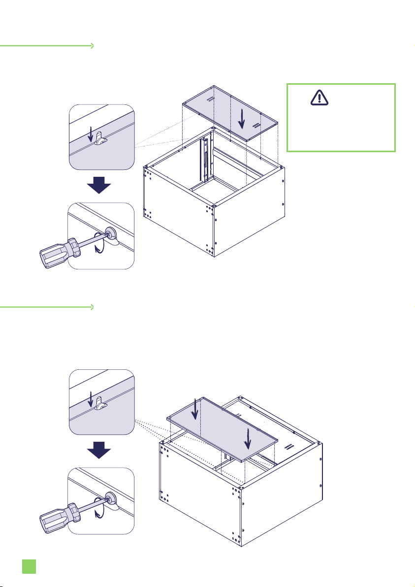
P3 CEILING 3000010641 3000010561 - STEEL 1 PC 30,26'' 18,11'' 1,38''
P4 REAR 3000010620 3000010524 - STEEL 1 PC 30,26'' 18,11'' 1,38''
P5 TOP BACK 3000010633 3000010539 - STEEL 1 PC 27,50'' 13,56'' 0,57''
P6 BOTTOM BACK 3000010592 3000010469 - STEEL 1 PC 27,50" 13,56'' 0,57''
P7 GUI DE 3000010652 3000010576 - STEEL 1 PC 30,04'' 1,14'' 0,93''
P8 SHELF 3000010622 3000010526 - STEEL 1 PC 30,26'' 18,11'' 1,38''
P9 DRAWER'S RIGHT SIDE - - 3000010672 STEEL 1 PC 16,14'' 6,79'' 0,73''
P10 DRAWER'S LEFT SIDE - - 3000010671 STEEL 1 PC 16,14'' 6,79'' 0,73''
P11 DRAWER'S BACK - - 3000010673 STEEL 1 PC 26,45'' 6,79'' 0,73''
P12 DRAWER'S BOTTOM - - 3000010669 STEEL 1 PC 26,41'' 16,22'' 0,40''
P13 DRAWER'S FRONT WI TH LOCK 3000010647 - 3000010555 STEEL 1 PC 27,36'' 8,82'' 0,98''
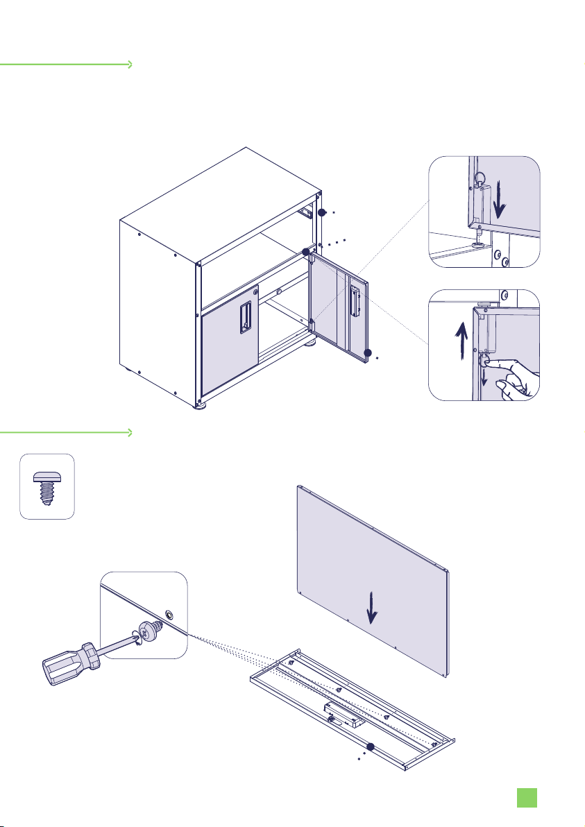
P14 RIGHT DOOR 3000010610 - 3000010494 STEEL 1 PC 16,50'' 13,56'' 0,98''
P15 LEFT DOOR 3000010611 - 3000010495 STEEL 1 PC 16,50'' 13,85'' 0,98''
QUANTITY
IDENTIFY THE COLOR OF YOUR CABINET
DIMENSION

F18
1000011849
Qty. 19
Assembled product:
H: W: L:32.3’’ 30.3’’ 18.1’’
Hardware list
F9
1000008368
Qty. 4
4
F7
1000008301
Qty. 4x
F13
1000011850
Qty. 1x
F15
1000010159
Qty. 2x
Locking nut, no key tightening required.
F1
1000011853
Qty. 26
SCREW M8X12
F2
1000011851
Qty. 26
NUT M8
HEXAGON 5mm
SCREW 4,8X9,5mm

P2
STEP 1
STEP 2
6
1 -
Fit the REAR inside the LEFT SIDE.
5
2 -
Align the two holes in the corner
and screw F1 and F2 to it.
1 -
Fit the REAR inside the RIGHT SIDE.
2 - Align the two holes in the corner and screw F1 and F2 to it.
REAR
LEFT SIDE
REAR
LEFT SIDE
RIGHT SIDE
4x
F2
4x
F1
4x
F2
4x
F1
1
2
1
2

180°
180°
STEP 3
STEP 4
6
1 -
Fit the CEILING between the RIGHT SIDE and LEFT SIDE.
2 - Check that all 4 tabs have been fitted.
3 - Fit the CEILING part to the corners of
the RIGHT and LEFT SIDES. Align the
holes and screw F1 and F2 to it.
1 -
Turn the cabinet with
the back side upwards.
2 - Align the holes and screw F1 and F2 to
it to each corners.
Check if all parts are
correctly positioned to
ensure product alignment.
Important -
REAR
LEFT SIDE
RIGHT SIDE
CEILING
8x
F2
8x
F1
8x
F2
8x
F1
1
2
REAR
LEFT SIDE
RIGHT SIDE
CEILING
REAR
RIGHT
SIDE
CEILING
LEFT SIDE

STEP 5
STEP 6
6
1 -
Fit the TOP BACK into parts RIGHT SIDE, LEFT SIDE and
CELING. C heck if all parts are supported over the bolts holes.
7
2 - After fitting the parts, screw the bolts until locked.
1 -Fit the BOTTOM BACK into the RIGHT SIDE, LEFT SIDE and
the REAR. Check if all parts are supported over the bolts holes.
2 -After fitting the parts, screw the bolts until locked.
Position the TOP BACK
on the CELING side to
assemble the cabinet.
Important
BOTTOM BACK
LEFT SIDE
RIGHT
SIDE
REAR
TOP BACK
TOP BACK
2
1
REAR
RIGHT
SIDE
CEILING
LEFT SIDE
2
1

STEP 7
STEP 8
8
1 -
Screw the leveling leg F9 into each of the four rivet nuts
located at the corners of the cabinet as shown. To level the
height or the cabinet, turn the Leveling Leg either clockwise
or counterclockwise to align it.
1 -
Turn the cabinet so that it will stand in the position of use.
2 -
F ix the four F7 parts to both SIDES as shown below.
REAR
RIGHT SIDE
LEFT SIDE
CELING
4x
F9
4x
F7
REAR
LEFT SIDE
RIGHT SIDE
CELING
1
2

GUIDE
STEP 9
STEP 10
69
1 -
Fit the lower the SHELF in diagonal position to insert it inside
the cabinet.
2 - Lean the SHELF and place it over the F7 fixed on the SIDES
as detailed in the illustration below.
3 - Place the other side of the SHELF.
1 -
Fit the GUIDE above the SHELF in the cut out parts at the
SIDES of the cabinet.
2 - Align the holes and screw F1 and F2 to it to each corners,
as illustrated (1 and 2).
LEFT SIDE
F7
LEFT SIDE
RIGHT SIDE
SHELF
REAR
CELING
2x
F2
2x
F1
RIGHT SIDE
SHELF
REAR
CELING
1
2

STEP 11
10
1 -
To assembly the doors, fit the RIGHT DOOR lower hinge bolt
inside the hole in the REAR.
2 - Then, pull down the pin of RIGHT DOOR upper hinge; align
the door and release the pin to fit the hole in the GUIDE.
1 -
Fit the DRAWER´S BOTTOM in the DRAWER´S FRONT.
2 -Screw the two parts with F18.
3 - Repeat the step for the LEFT DOOR.
4x
F18
DRAWER´S BOTTOM
DRAWER´S FRONT
STEP 12
GUIDE
REAR
LEFT SIDE
LEFT DOOR
RIGHT DOOR
RIGHT SIDE
SHELF
CELING
2
1

STEP 13
STEP 14
9
1 -
Align the DRAWER´S RIGHT SIDE and DRAWER´S LEFT SIDE
to the DRAWER´S BOTTOM, until it leans against piece the
DRAWER´S FRONT.
2 - Screw them with F18.
DRAWER´S RIGHT SIDE
1 -
Insert DRAWER´S BACK over the DRAWER´S BOTTOM
and between the DRAWER´S RIGHT SIDE and
DRAWER´S LEFT SIDE.
2 - Then, screw the DRAWER´S BACK to the DRAWER´S RIGHT
SIDE, DRAWER´S LEFT SIDE and DRAWER´S BOTTOM,
with F18.
DRAWER´S LEFT SIDE
DRAWER´S FRONT
DRAWER´S BOTTOM
DRAWER´S RIGHT SIDE
DRAWER´S BOTTOM
DRAWER´S FRONT
DRAWER´S BACK
DRAWER´S LEFT SIDE
9x
F18
6x
F18

Left Right
STEP 15
8
1 -
Fit the drawers - already
assembled-between the
RIGHT SIDE and LEFT SIDE,
through the drawer slides.
2 -
Check if the drawer slides on
both sides are properly fitted. If
they are not properly fitted, the
drawer will not close completely.
Slide the drawer in and out to test
it and be sure it is sliding smoothly.
3 -
The pocedure for removing the
drawer is illustrated above.
RIGHT SIDE
LEFT SIDE

WARRANTS TERMS AND CONDITIONS
ITBE PRODUCTS
This document describes the limited warranty agreement ('Warranty') regarding your purchase of
ITBE's furniture and/or equipment ('Product') within USA territory. This agreement is subject to
the conditions described below.
1. WARRANTY SCOPE
This Warranty covers Product defects resulting from defective parts, materials or 1.1.
manufacturing, if such defects occur during the period of 12 months after the date of purchase.
The Products are considered defective if they fails to perform the functions as indicated in the 1.2.
operation manuals, technical speciications or any other similar documents supplied with the
Products, and the failure is due to material and workmanship defects.
. During the Warranty period, if a defect arises in the Product, ITBE will, at his option and to the 1.3
extent permitted by law, either (i) repair the Products using either new or refurbished parts, (ii)
replace the Product with a new or refurbished Product that is equivalent or similar to the Product
to be replaced, or (iii) refund to Buyer all or part of the purchase price of the Product.
. 2WARRANTY LIMITATIONS
. 2.1 This Warranty does not cover:
i. In-home service including, but not limited to, service calls to correct the installation of any
Products or to instruct Buyer on how to use or install them.
ii. Damage or failure resulting from modiication, alteration, misuse or abuse of a Product.
iii. Damage caused by a carrier or third party, including resulting from improper handling
or shipping of Products, or Products damaged by accident, alteration, misuse, abuse, ire,
lood, improper installation, acts of God, neglect, corrosion, modiication or mishandling.
iv. Factory speciied replacement parts or Product replacement when Buyer's Product is
used in other than normal, single-family household use, such as a commercial environment
or handled in a manner contrary to published user or operator instructions and/or
installation instructions.
v. Aesthetic damages including scratches, dings, dents or cracks that do not afect the
structural or functional capability of the Product.
vi. Damage resulting from improper loading beyond the speciied maximum weight
capacity outlined in the assembly instructions provided with the Product including
overloading of hooks, baskets, shelves, cabinets, and other accessories used with the
Product.
vi. Surfaces damaged due to chemical interaction resulting in corrosion of paint, metal or
any treatment or cleaning product that is not recommended by ITBE.
vii. Color and other covering materials.
ix. Drawers and doors, as they may run tight or lose due to high variation in humidity and
temperature in the surrounding atmosphere.
x. Replacement keys or locking mechanism.
xi. Natural wear and tear of the Product.
xii. Any labor costs during the Warranty period.
2.2 ITBE must be notiied of any defect and given an opportunity to remedy it; any remedial work
carried out by a third party will nullify this warranty.
2.3 The cost of repair or replacement under these excluded circumstances shall be borne by Buyer.

3. PROCEDURE AND EVALUATION
3.1 If Buyer has received a defective Product, Buyer must report the defect by sending an e-mail
to To be able to [email protected] make a warranty claim, Buyer must always present proof
of purchase send a photo of the defective Product and provide a detailed description of the
defect.
3.2 Buyer will receive a conirmatory email with a number code and ITBE will process the report
within 2 business days. If the photo sent by Buyer is not enough to determine the cause of the
Product defect, ITBE may request further explanation, carry out an on-site examination of the
Product or require Buyer to send the Product to the nearest support center. If an on-site
examination is necessary, Buyer must grant free direct access to ITBE's technician as needed.
3.3 If there is any doubt about whether the problem with the defective Products falls under the
Warranty, the burden of proof of the existence of material and workmanship defects lies with
Buyer.
3.4 Warranty services will be provided only if a material or workmanship defect is demonstrated,
and the defect does not fall under clause 2.
3.5 After evaluation, ITBE will, on its discretion, either repair or replace the defective parts of
the Product or the Product itself or refund the purchase price to Buyer. ITBE shall provide Buyer
with a forecast of the time required for the repair or replacement of the Product.
3.6 If a product or its part has to be replaced and that particular product or part is no longer
available, ITBE reserves the right to use an alternative similar product or part.
3.7 When a warranty claim is justiied, ITBE will pay for shipping expenses for repairing or
replacing the Product. ITBE can charge Buyer for returned Products that are not found to be
defective or non-conforming, in addition to shipping-test, and handling costs associated
therewith.
3.8 The warranty does not cover any costs associated with installation, removal or reinstallation
of a Product, when applicable.
4. WARRANTIES AND DAMAGES
4.1 To the extent permitted by law, the Warranty and remedies set forth above are exclusive and
in lieu of all other warranties and remedies. ITBE speciically disclaims all statutory or implied
warranties, including, but not limited to, warranties of merchantability, itness for a particular
purpose and against hidden or latent defects.
4.2 ITBE DOES NOT PROVIDE, AND SPECIFICALLY DISCLAIMS, ANY OTHER WARRANTIES
FOR THE PRODUCTS, EXPRESS OR IMPLIED, INCLUDING ANY IMPLIED WARRANTY OF
MERCHANTABILITY OR FITNESS FOR A PARTICULAR PURPOSE. ITBE SHALL NOT BE
LIABLE FOR OR OBLIGATED IN ANY WAY TO PAY CONSEQUENTIAL OR INDIRECT DAMAGES,
INCLUDING, WITHOUT LIMITATION, LOSS OF PROFITS, FINES OR LEGAL ACTIONS BY THIRD
PARTIES. IN ANY EVENT, ITBE'S LIABILITY AS RELATED TO THE SUPPLY OF THE PRODUCT
SHALL NOT EXCEED THE AMOUNT EFFECTIVELY PAID BY THE BUYER.
4.3 ITBE is not obliged to notify any Buyer, or future Buyer, after a certain date about any
possible amendments or the non-applicability of this limited warranty regarding the supplied
Products. The Warranty as described below is subject to the limits and other conditions
described herein.

Keep this booklet and your proof of purchase together for future reference. You will need to
provide proof of purchase to obtain service under warranty.
Write the following information regarding your Product to help you get Better assistance or
service should you ever need it.
You should have the complete model number. You can ind this information on the label that is
located in the package. as an example below:
Distributor name _________________________________________
Address_______________________________________________________
Phone number_____________________________________________
Model number _____________________________________________
Serial number ________________________________________________
Date of purchase _______________________________________________
ITBE
PD 1P-35 ITBE EASY FIT BRM/BRM
0001/0003 00000000 00/00/00 1 2 3 4 5 6 4 5 1 0 0 0 0
OF FABRICAÇÃO / PRODUCTION /
FABRICACION
PRODUCT IDENTIFICATION
7892946315555
PACKED SIZE:
GROSS WEIGTH:
VOL/UNIT:
1234564510000
COPY THIS NUMBER
Assembed Product
13.77" X 25.19" X 11.22" IN
Contact us.
Need
Help?
Any questions
on the assembly ?

itbehome.com
This manual suits for next models
2
Table of contents
Other itbe Indoor Furnishing manuals
Popular Indoor Furnishing manuals by other brands

fantastic furniture
fantastic furniture Gelato quick start guide

Whittier Wood
Whittier Wood McKenzie Alder 1613b Assembly instructions

Teknion
Teknion Navigate Mid Gable-Solid Installation guides

Jahnke
Jahnke CRAFT D 151 manual

BLACK RED WHITE
BLACK RED WHITE NIKA NKG-80/72 Assembly manual

De La Espada
De La Espada REFECTORY EXTENDING TABLE Assembly instructions

Bush Business Furniture
Bush Business Furniture WC12924 manual

Hillsdale Furniture
Hillsdale Furniture La Croix 2132-660 quick start guide

Vivo
Vivo DESK-TOP2CB instruction manual

AmazonBasics
AmazonBasics B07SPYD4MW manual

Core Products
Core Products AG915 manual

Next
Next MALVERN 273442 Assembly instructions