4
1.- GENERAL DESCRIPTION
MULTIFERTIC dosing pumps are heavy duty, high precission electric piston or
diapragm pumps for dosing liquid products.
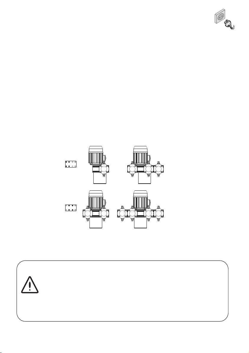
They are made up of one driving module and 1 to 4 injection modules. The
available heads are from 25 to 500 l/h for the piston series, and from 18 to 300
l/h for the diafragm series,independently regulated by means of a system of
POSITIVE RETURN, exclusive to I.T.C.
In the same injector can be connected several injection modules to apportion
different products (INDEPENDENT INJECTION) or to increase the injection
flow. The design of this dosing pump allows the combination of piston modules
with diaphragm modules in the same pump. By increasing the number of
modules in the same injector, a higher flow regularity is obtained, whereby in
the 4 module model an actually continuous flow is obtained. Injection modules
may be connected in the factory or added later when the injector is in place.
MULTIFERTIC dosing pumps are manufactured with materials that can resist
the existing agrochemical products, even acids. It is designed for all sorts of
processes where it is necessary to dose a product into a hydraulic network,
such as: food, textile, chemical industry, water treatments, etc. (See materials
in Technical Features). In case there is any doubt about compatibility of
materials with the products to be used please contact with ITC S.L. Technical
Service.
Dosing flow of each module is adjustable independently with no need to stop
the pump from 0% to 100% of its capacity.
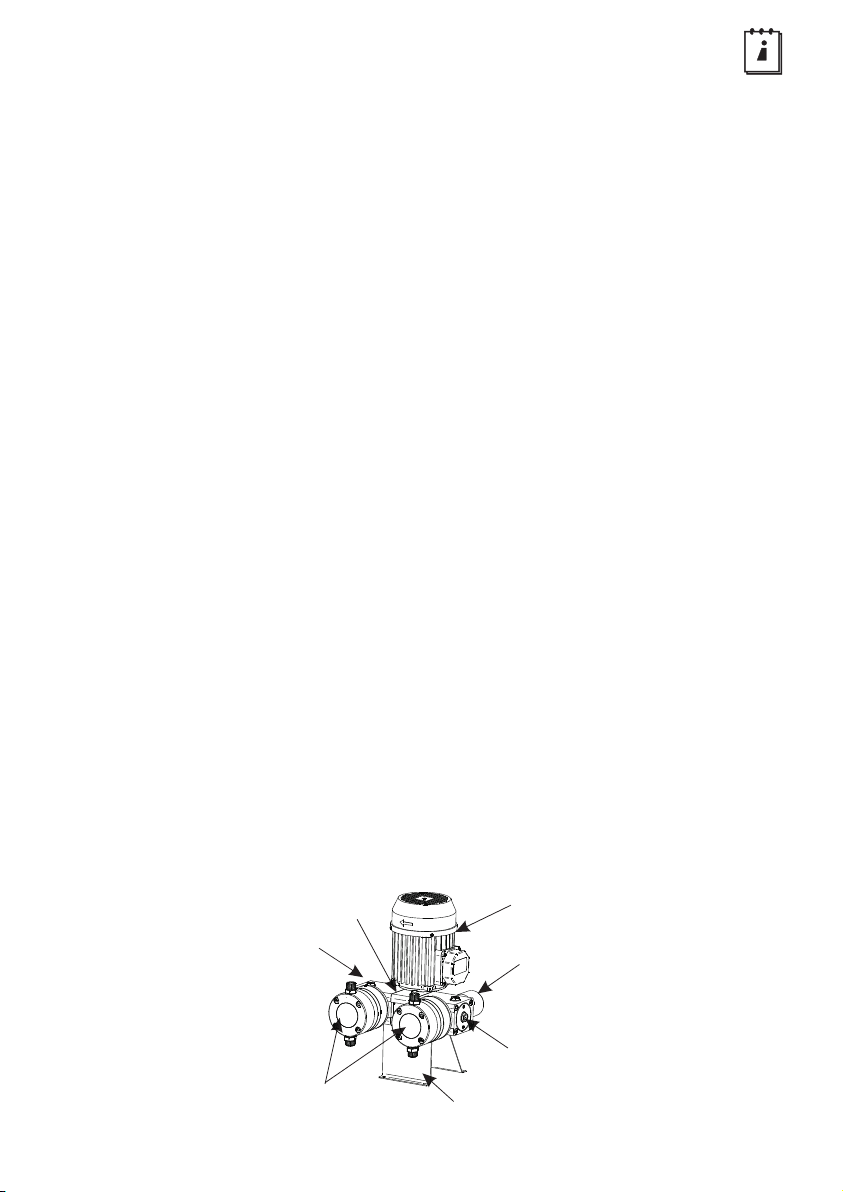
It is made up as follows:
Motor
Cylinder
Motor module
Additional module
Support
Regulator
Motor block
5
Codes formulation
62 - A 2 1 - B P 0 P M
MOTORMOTOR REDUCCIÓN
2: 2 cycles.
1: 1 cycle.
FREQUENCY
P: PP - PEUHMW / PTFE
C: PP - Ceramic / PTFE
I : AISI316 - Ceramic / PTFE
F: PVDF - Ceramic / PTFE
T: PTFE - Ceramic / PTFE
A: PP - AISI316 /
MATERIAL
Cylinder - Piston / Diaphragm
62 - S P 0 P M
M: 3/4"
S: ADDITIONAL MODULE
A: 3Ph 230/400V
B: 1Ph 230V 50Hz
C: 1Ph 110/230V 60Hz
D: 12V DC 130W
E: 12V DC 300W
F: 24V DC 130W
G: 24V DC 300W
B: MAIN MODULE
Q0: Piston 25 (1 cycle)
P0: Piston 50 (2 cycles)
P1: Piston 100 (2 cycles)
P2: Piston 200 (2 cycles)
P3: Piston 300 (2 cycles)
P5: Piston 500 (2 cycles)
F0: Diaphragm 25 (1 cycle)
D0: Diaphragm 50 (2 cycles)
D1: Diaphragm 100 (2 cycles)
D2: Diaphragm 200 (2 cycles)
D3: Diaphragm 300 (2 cycles)
CAUDAL
FLOW
CONEXION
Q0: Piston 25 (1 cycle)
P0: Piston 50 (2 cycles)
P1: Piston 100 (2 cycles)
P2: Piston 200 (2 cycles)
P3: Piston 300 (2 cycles)
P5: Piston 500 (2 cycles)
F0: Diaphragm 25 (1 cycle)
D0: Diaphragm 50 (2 cycles)
D1: Diaphragm 100 (2 cycles)
D2: Diaphragm 200 (2 cycles)
D3: Diaphragm 300 (2 cycles)
CAUDAL
P: PP - PEUHMW / PTFE
C: PP - Ceramic / PTFE
I : AISI316 - Ceramic / PTFE
F: PVDF - Ceramic / PTFE
T: PTFE - Ceramic / PTFE
A: PP - AISI316 /
MATERIAL
Cylinder - Piston / Diaphragm M: 3/4"
FLOW CONEXION
62 - ENS 2
CAUDAL
ASSEMBLY
1: 1 Modue
2
3: 3 Modules
4: 4 Modules
: 2 Modules
NUMBER OF MODULE