ITE K-3000 User manual

1
*
1
B
-
9.1
.
7
-
4
LOW
-
VOITAGE
POWER
CIRCUIt
BREAKERS
PAGE
2
CONU
Nrs
Page
Introduction
Receiving
and
Storage
Basic
Handling
Instructions
Circuit
Breaker
Operation
Circuit
Breaker
Rating
Closing
Spring
Operation
Escutcheon
Operating
Feutuies
Ciicuil
Brt
-
*
uki
*
r
Hnmaplnt
*
Manual
\
hinging
lltuidh
;
MIIIHKJI
Tup
Button
.
.
Circuit
Breaker
“
Open
*
'
or
"
Closed
"
ln
»
|
Uu
|
0
,
Automatic
Trip
Indicator
Automatic
Trip
Alarm
Contacts
Automatic
Trip
Lockout
Padlocking
Device
Closing
Spring
Charge
Indicator
Motor
Disconnect
Switch
Electrical
Close
Push
Button
.
.
.
Manual
Close
Lever
Rrukmq
Mechanism
(
Diawout
BMML
-
Opcrution
of
Devices
Electro
-
Mechanical
Overcurrent
Trip
lv
Power
Shield
Solid
State
Overcurimi
|
ll
(
>
Qevjces
Control
Relay
Auxiliary
Switches
Undervoltage
Trip
Device
Installation
,
Initial
Testing
and
Removal
Installation
Checking
Circuit
Bieuker
Operation
Mtlll
’
Kil
{
OptfUlltOM
.
.
Circuit
Breaker
Removal
(
Orawout
Typei
Maintenance
and
Adjustments
Safety
Notes
Periodic
Maintenance
Inspection
...
Arc
Chutes
Insulation
Structure
Contacts
Contact
Pitting
Contact
Pressure
Check
and
Adjustmo
Manual
Slow
Close
to
Check
Contact
.
*
*
Operating
Mechanism
Primary
Trip
Latch
Tripper
Bar
Adjustment
Primary
Close
Latch
Shunt
Trip
Device
Magnetic
Latch
Device
Electro
-
Mechanical
Overcurrent
Trip
D
:
*
\
Solid
State
Overcurrent
Trip
Device
Se
*
-
.
^
Lubrication
Dielectric
Test
Electrical
Characteristics
of
Control
Renewal
Parts
3
3
3
3
3
3
l
»
f
>
S
S
5
5
6
a
i
o
6
'
ices
o
8
8
(
8
o
0
o
10
10
10
10
10
10
10
10
1
•
1
•
13
13
13
13
13
13
v
.
*
Adjustments
.
.
.
.
1
5
15
15
•
»
i
lc
{
1
c
Courtesy of NationalSwitchgear.com

IB
-
9.1
.
7
-
4
LOW
-
VOLTAGE
POWER
CIRCUIT
BREAKERS
PAGE
3
(
INSTRUCTIONS
FOR
TYPE
K
-
3000
,
K
-
4000
,
K
-
3000
S
,
K
-
4000
S
CIRCUIT
BREAKERS
Stationary
Switchboard
Mounted
and
Drawout
Mounted
INTRODUCTION
Circuit
breakers
should
be
installed
in
their
perma
-
nent
location
as
soon
as
possible
.
(
See
Basic
Handling
below
.
)
If
the
breakers
are
not
to
be
placed
in
service
for
some
time
,
it
is
advisable
to
provide
adequate
means
of
protection
fins
may
bt
;
done
kipping
Mu
-
Ineuker
nr
it
-
'
kid
Tvpnni
)
with
wiilrM
fmmf
pupet
<
_
md
seciluuj
Tij
prevent
mtillmtmn
«
>
t
»
KiT
Where
*
r
.
-
ndirimv
at
high
humidify
|
>
i
»
*
vml
(
111
«
.
*
•
u
-
.
»
r
heviftri
'
;
memtcd
These
instructions
apply
to
the
type
K
-
3000
and
K
4000
,
K
3000
$
and
K
-
4000
S
circuit
breakers
;
3000
and
4
UttO
ampere
UL
continuous
current
rating
respur
•
tv
ih
~
type
3
K
-
tnnp
find
K
4000
ate
equipped
-
vith
It
•
Aiiiui
.
liumcu
!
oven
uirent
Trip
devices
,
WIU
.
*
M
?
O
*
.
t
/
pe
k
JU
00
S
and
K
4000
$
incorpomle
the
snlid
nvcicurrent
trip
devices
.
A
K
-
3000
S
circuit
breaker
is
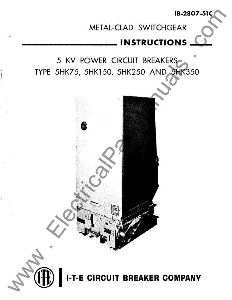
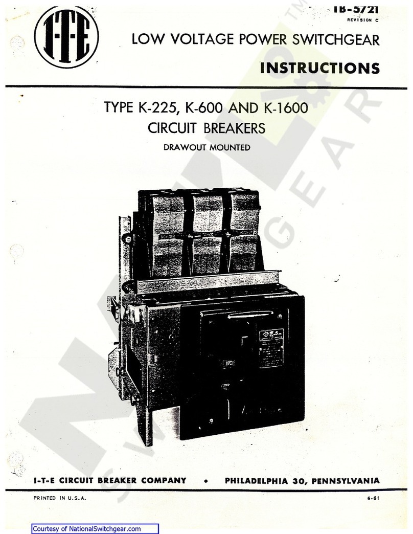
shown
on
the
front
cover
of
this
bulletin
.
The
K
-
3000
and
K
-
4000
circuit
breakers
can
be
fur
-
nished
with
two
or
three
poles
for
dc
or
ac
operation
.
K
-
3000
S
and
K
-
4000
S
circuit
breakers
are
only
fur
-
nished
for
three
pole
ac
operation
.
All
circuit
breakers
can
be
furnished
as
drawout
or
stationary
mounted
and
are
available
as
manually
or
electrically
operated
,
and
with
electrical
control
devi
*
es
available
in
various
at
.
and
dc
voltage
combinations
.
Many
optional
features
are
also
available
.
An
electrical
operated
,
drawout
type
circuit
breaker
is
shown
in
Figure
1
,
with
a
typical
schematic
diagram
shown
in
Figure
2
.
These
instructions
should
be
read
thoroughly
before
handling
,
installing
and
/
or
operating
the
circuit
breaker
.
<
«
.
I
na
-
tal
-
i
i
)
|
i
'
BASIC
HANDLING
INSTRUCTIONS
Once
the
circuit
breaker
has
been
unbolted
and
re
-
moved
from
its
shipping
skid
,
it
should
be
turned
to
the
upright
position
and
placed
on
a
flat
surface
to
avoid
damage
to
breaker
parts
.
For
safety
,
all
handling
in
this
position
should
utilire
the
lifting
yoke
(
2 0
)
shown
in
Figure
I
CIRCUIT
BREAKER
OPERATION
CIRCUIT
BREAKER
RATING
(
The
K
-
3000
/
K
-
3000
S
and
K
-
4000
/
K
-
4000
S
circuit
breakers
are
designed
to
carry
a
maximum
ac
contin
-
uous
current
of
3000
amperes
and
4000
amperes
re
-
spectively
.
Exceeding
these
ratings
may
raise
the
tem
-
perature
of
the
breakers
beyond
their
design
limit
and
thus
affect
the
life
of
the
breaker
,
Thus
,
any
long
tin
e
f
)
i
4
'
!
|
)
setting
t
*
xre
«
'
dim
|
tOD
'
V
.
.
of
the
fmine
sire
is
»
o
be
user
!
only
foi
coordination
,
not
tor
currying
increased
continuous
current
.
RECEIVING
AND
STORAGE
Immediately
upon
receipt
ot
the
circuit
breaker
>
,
CA
-
amine
the
cartons
to
determine
if
any
damage
or
loss
was
sustained
during
transit
.
If
injury
or
rough
handling
is
evident
,
file
a
damage
claim
at
once
with
the
carrier
and
promptly
notify
the
l
-
T
-
E
Imperial
Corporation
.
The
l
-
T
-
E
Imperial
Corporation
is
not
responsible
for
dam
-
age
of
goods
after
delivery
to
the
carrier
.
However
,
the
l
-
T
-
E
Imperial
Corporation
will
lend
assistance
if
noti
-
fied
of
claims
.
Unpack
the
circuit
breakers
as
soon
as
possible
after
receipt
.
If
unpacking
is
delayed
,
difficulty
may
be
ex
-
perienced
in
making
a
claim
for
damages
not
evident
upon
receipt
.
Use
care
in
unpacking
in
order
to
avoid
damaging
any
of
the
circuit
breaker
parts
.
Check
the
contents
of
each
carton
against
the
packing
list
before
discarding
any
packing
material
.
If
any
shortage
of
material
is
discovered
,
promptly
notify
the
nearest
rep
-
resentative
of
the
M
-
E
Imperial
Corporation
.
Informa
-
tion
specifying
the
purchase
order
number
,
carton
num
-
ber
and
part
numbers
of
the
damaged
or
missing
parts
should
accompany
the
claim
.
CLOSING
SPRING
OPERATION
The
two
closing
springs
supply
the
power
that
doses
the
circuit
breaker
and
also
charge
the
two
opening
springs
during
the
closing
operation
.
The
closing
springs
are
charged
by
a
motor
in
the
electrically
operated
breaker
and
charged
by
hand
in
the
manually
operated
breaker
;
however
,
in
either
type
,
the
springs
are
charged
the
same
amount
and
when
charged
,
the
spring
energy
is
available
to
close
the
breaker
,
thus
referred
to
as
"
stored
energy
.
”
The
closing
springs
are
normally
charged
when
the
breaker
is
opened
.
If
charged
after
closing
,
the
breaker
may
be
opened
and
then
reclosed
without
recharging
the
springs
.
In
drawout
breakers
,
the
closing
springs
are
automatically
dis
-
charged
when
the
breaker
is
moved
from
the
dis
-
connected
to
the
withdrawn
position
(
shown
in
Figure
I
I
.
This
prevents
accidental
discharge
.
i
These
instructions
do
not
purport
to
cover
all
details
or
variations
in
equipment
nor
to
provide
tor
every
possible
contingency
to
be
met
in
connection
with
installation
,
operation
,
or
maintenance
.
Should
further
information
be
desired
or
should
particular
problems
arise
which
are
not
covered
suf
-
ficiently
for
the
purchaser
'
s
purposes
the
matter
should
be
referred
to
the
l
-
T
-
E
Imperiol
Corporation
.
Courtesy of NationalSwitchgear.com

IB
-
9.1
.
7
-
4
LOW
-
VOLTAGE
POWER
CIRCUIT
BREAKERS
’
AGE
4
I
(
I
1
.
Arc
Chute
2
.
Arc
Chute
Retainer
Molding
3
.
Arc
Chute
Mounting
Screw
*
4
.
Shutter
*
5
.
Visual
Indicator
(
or
Breaker
“
Closed
"
or
“
Opened
"
6
.
Manual
Close
Lever
7
.
Manual
Charging
Lever
8
.
Manual
Trip
Button
9
.
Automatic
Trip
Indicator
10
.
Motor
Disconnect
Switch
M
.
Spring
Retainer
Bracket
12
.
Manual
Charge
Handle
13
.
Racking
Crank
14
.
Closing
Spring
Charge
Indicator
15
.
Orawout
Lever
16
.
Racking
Cam
Rollers
17
.
Racking
Crank
Opening
18
.
Wheels
‘
19
.
Shutter
Lock
Screw
(
Inserted
in
Shutter
)
20
.
Lifting
Yoke
21
.
Closing
Spring
Charging
Motor
22
.
tleciiical
Close
Button
23
.
Locking
Hasp
24
.
Auxiliary
Switch
25
.
Nameplate
26
.
Plate
*
Not
Visible
in
This
View
(
Fig
.
1
—
Typical
Electrically
Operated
,
Drawout
Type
K
-
3000
Circuit
Breaker
Courtesy of NationalSwitchgear.com

IB
-
9.1
.
7
-
4
LOW
-
VOLTAGE
POWER
CIRCUIT
BREAKERS
PAGE
5
ESCUTCHEON
OPERATING
FEATURES
This
device
is
on
indicator
only
and
does
not
prevent
the
circuit
breaker
reclosmg
.
Upon
an
overcurrent
trip
operation
,
the
indicator
protrudes
from
the
front
plate
approximately
t
/
j
inch
.
The
automatic
trip
indicator
should
be
reset
after
each
trip
indication
by
pushing
back
into
its
normal
latch
position
.
The
operator
should
investigate
the
cause
of
tripping
before
resetting
the
automatic
trip
indicator
and
subsequent
reclosing
the
circuit
breaker
after
an
outage
which
results
in
an
operation
of
the
indicator
Automatic
Irip
Alarm
Contacts
I
Hand
Reset
I
f
AAanually
and
electrically
operated
circuit
breakers
are
provided
with
an
extendible
escutcheon
face
plate
.
This
escutcheon
provides
a
central
area
for
the
controls
which
are
mounted
directly
on
the
circuit
breaker
.
The
controls
for
manually
operated
circuit
breakers
.
Figure
1
,
included
in
the
escutcheon
face
plate
are
:
(
2 5
)
a
nameplate
giving
the
various
ratings
assigned
to
the
particular
type
of
circuit
breaker
,
(
1 2
)
the
manual
charging
handle
,
(
8
)
the
manual
trip
button
,
15
)
the
‘
OPEN
"
and
“
CLOSED
”
position
indicator
,
(
9
)
In
*
nutomritir
trip
indicator
with
optional
facilities
lor
f
,
,
jio
-
M
-
xkimj
Hit
?
f
in
oil
blanker
m
1
L
5
(
or
DISCONNECTED
positions
,
and
[
Ml
inn
spring
rlmrgtfig
indbolui
The
controls
for
the
electrically
operated
c
in
uit
breakers
,
Figure
1
,
are
the
same
as
the
manually
oper
ated
circuit
breakers
except
the
charging
handle
(
1 2
)
is
removed
and
stored
for
maintenance
use
,
and
the
presence
of
(
1 0
)
motor
disconnect
switch
for
the
motor
electrical
circuit
and
122
)
electrical
close
push
button
switch
.
r
?
-
»
i
•
,
1
;
•
n
-
-
1
*
il
i
|
|
>
!
l
Hi
r
i
(
OMNI
4
HD
(
t
If
M
*
f
)
U
>
f
»
-
"
l
*
-
i
111
«
O
I
wtm
h
is
optional
shows
when
automatir
tupping
has
occurred
.
Hus
is
accomplished
l
)
/
adding
a
pic
hior
snap
switch
to
the
automatic
trip
indicator
assembly
The
automatic
trip
indicator
actuates
the
lullei
on
the
alarm
switch
which
in
turn
causes
a
noimall
^
open
contact
to
close
and
a
normally
closed
contact
to
open
on
overcurrent
trip
.
The
alarm
contact
is
manuull
/
reset
by
pushing
the
trip
indicator
(
9
)
back
into
its
normal
position
.
.
a
.
1
l
<
n
<
las
The
manually
and
ele
^
tncnll
/
operated
drnwout
nr
cuil
bleaker
escutcheon
also
contains
the
rucking
crank
opening
(
1 7
)
and
interlocking
diawout
lever
(
1 5
)
.
Automatic
Trip
Lockout
(
Hand
Reset
)
(
figure
|
(
|
p
-
m
9
)
An
additional
device
(
which
is
also
optional
)
may
be
added
to
the
automatic
trip
indicator
assembly
de
-
vice
which
serves
to
mechanically
prevent
reclosiug
the
circuit
breaker
after
an
automatic
trip
operation
When
the
trip
indicator
is
pushed
in
the
circuit
breaker
mechanism
can
then
be
operated
to
close
the
circuit
breaker
contacts
.
Padlocking
Device
(
Figure
I
It
All
K
line
firci
.
it
breakers
fire
equipped
with
c
—
mi
-
of
p
‘
H
.
lio
<
-
.
k
I
fig
th
'
•
H
'
.
Ult
free
position
.
This
is
accomplished
by
the
use
<
if
n
locking
plate
to
maintain
the
manual
tiip
button
m
n
tripping
direction
when
the
locking
plate
is
field
for
-
ward
by
one
or
more
padlocks
.
To
obtain
the
condi
-
tion
for
padlocking
the
circuit
breaker
in
the
open
position
,
the
manual
trip
button
is
pushed
inward
.
Then
the
padlock
plate
is
pulled
out
and
the
padlock
in
-
serted
into
the
veitical
slot
.
In
this
position
,
the
mechan
-
ism
is
maintained
trip
free
and
the
contact
arm
canno
*
be
moved
to
the
closed
position
.
On
circuit
breakers
equipped
with
drawoul
mechanism
the
padlocking
device
is
associated
with
the
drawou
*
interlocking
mechanism
so
that
the
circuit
breaker
can
-
not
be
moved
from
any
of
its
three
basic
drawout
posi
-
tions
of
“
CONNECTED
,
”
“
TEST
”
or
“
DISCONNECTED
‘
with
the
padlocking
in
effect
.
Closing
Spring
Charge
Indicator
(
Figure
I
,
Item
14
)
Under
normal
operating
conditions
,
Ihe
closing
springs
are
automatically
charged
after
each
tripping
operation
.
However
,
there
are
occasions
when
the
springs
will
be
in
a
discharged
state
.
Therefore
,
it
is
desirable
that
means
be
available
to
indicate
the
charged
or
uncharged
condition
of
the
closing
springs
.
This
is
accomplished
by
a
visual
indicator
seen
through
an
aperture
in
the
escutcheon
plate
.
The
indicator
is
marked
“
CHARGED
”
and
“
UNCHARGED
.
”
A
self
-
aligning
plate
,
immediately
behind
the
es
-
cutcheon
face
plate
,
is
used
to
exclude
dust
from
the
circuit
breaker
compartment
.
On
drawout
type
circuit
breakers
,
the
escutcheon
foce
wiil
protrude
through
Ihe
front
door
of
Ihe
compartment
when
the
circuit
breaker
is
in
the
“
TEST
”
and
“
DISCONNECTED
(
i
•
post
-
lions
.
In
these
positions
,
the
dustplate
still
functions
to
211
"
itr
•
•
luile
dust
•
h
*
I
‘
.
1
1
H
|
)
1
t
-
:
1
•
Ur
cult
Breaker
Nameplate
(
Figure
I
,
Item
25
)
The
circuit
breaker
nameplate
contains
information
regarding
(
I
)
the
manufacturer
’
s
name
and
address
,
(
2
)
type
of
circuit
breaker
design
,
(
3
)
serial
number
of
circuit
breaker
,
(
4
)
continuous
current
rating
of
frame
size
,
(
5
)
short
circuit
current
rating
at
rated
voltoges
,
(
6
)
frequency
,
(
7
)
short
time
current
.
Manual
Charging
Handle
(
Figure
1
,
Item
12
)
The
manual
charging
handle
is
a
T
-
shaped
lever
used
to
charge
the
closing
springs
by
pumping
approxi
-
mately
ten
times
.
Manual
Trip
Button
(
Figure
1
,
Item
8
)
The
manual
trip
button
,
when
pushed
,
trips
the
cir
-
cuit
breaker
to
“
OPEN
.
”
Circuit
Breaker
“
OPEN
"
or
“
CLOSED
"
Indicator
(
Figure
1
,
Item
5
}
This
indicator
shows
the
physical
position
of
the
circuit
breaker
contacts
.
Automatic
Trip
Indicator
(
Figure
!
,
Item
9
)
(
Not
including
undervoltage
,
alarm
switch
or
lockout
)
The
automatic
trip
indicator
is
provided
as
standard
equipment
on
the
K
-
line
*
circuit
breakers
and
is
used
to
indicate
the
operation
of
the
overcurrent
trip
device
.
Courtesy of NationalSwitchgear.com

1.1
.
7
-
4
LOW
-
VOLTAGE
POWER
CIRCUIT
BREAKERS
S
/
I
or
Disconnect
Switch
(
Figure
1
,
Item
10
)
he
motor
disconnect
switch
is
a
double
pole
,
single
-
w
toggle
type
switch
connected
in
series
with
the
rging
motor
circuit
and
is
used
to
disconnect
the
or
from
the
voltage
source
.
This
switch
is
used
(
1
)
,
in
it
is
desirable
to
prevent
automatic
recharging
of
closing
springs
just
prior
to
taking
the
circuit
aker
out
of
service
for
maintenance
and
(
2
)
,
for
itrol
wiring
dielectric
test
.
The
motor
must
be
dis
-
inectml
for
Hie
control
wiring
dielectric
test
rind
<
fricul
Close
Push
Button
(
Figure
I
,
Item
2
2
]
The
etprfrirol
close
push
button
is
used
to
electrical
!
/
ise
the
circuit
from
the
escutcheon
.
Hus
contact
n
nnected
in
series
with
the
latch
release
coil
.
Energiz
-
}
the
latch
release
coil
allows
the
charged
springs
to
>
se
the
circuit
breaker
.
anual
Close
Lever
(
Figure
)
,
Item
6
)
The
manual
close
lever
is
provided
on
all
circuit
cakers
to
provide
a
safe
means
of
closing
the
euker
without
<
ontrol
power
.
The
lever
is
provided
itit
a
ring
to
winch
a
lanyard
should
be
attached
for
osing
the
breaker
at
a
safe
distance
.
aching
Mechanism
(
Drawout
Breaker
)
racking
mechanism
is
used
lo
move
Ihe
circuit
to
any
one
of
its
three
positions
—
"
CON
-
"
TE
5
T
"
or
"
DISCONNECTED
.
"
All
of
these
ositions
are
attainable
with
the
cubicle
door
closed
r
opened
.
The
breaker
can
be
closed
only
when
the
Irawout
levin
{
1
Figure
1
)
is
up
and
when
up
,
the
riink
I
I
l
:
Figum
1
)
cannot
be
turned
.
fhe
circuit
bic
-
aker
must
be
in
the
OPEN
"
position
>
efore
lever
(
15
,
Figure
\
)
can
be
pushed
down
.
In
>
rder
to
move
the
circuit
breaker
from
one
position
to
mother
,
the
lever
must
be
pushed
down
and
the
crank
urned
;
once
turning
begins
,
the
lever
will
stay
down
jntil
another
position
is
reached
and
the
lever
will
map
up
,
preventing
additional
turning
,
until
the
lever
s
again
pushed
down
.
When
the
padlocking
device
is
locked
,
the
lever
(
15
)
is
locked
in
the
up
position
preventing
movement
of
the
racking
mechanism
.
Figure
1
shows
the
breaker
in
the
fully
withdrawn
position
.
There
are
two
sets
of
indicator
lines
on
the
left
side
of
the
breaker
to
show
breaker
position
.
One
set
is
visible
with
the
switchboard
door
closed
,
the
other
visible
when
the
door
is
open
.
device
must
be
properly
set
to
provide
adequate
pro
-
tection
for
an
electrical
system
.
Three
adjustment
screws
on
the
bottom
of
the
device
provide
independent
con
-
trol
of
the
long
-
time
pickup
,
instantaneous
pickup
and
amount
of
time
delay
.
The
nameplate
of
this
device
shows
the
setting
of
these
adjustments
and
the
range
of
settings
which
are
available
.
For
information
on
the
time
-
current
characteristics
of
this
device
,
request
a
copy
of
TD
-
6693
.
(
B
)
Type
OD
-
400
Selective
Overcurrent
Trip
Device
.
Ihe
type
OD
-
4
CJO
overcurrenl
trip
device
,
for
selective
ti
«
!
;
ljiiig
npphi
»
it
»
on
>
provides
long
-
time
delay
and
shmt
time
delay
flipping
.
Independent
adjustment
of
both
pickup
and
time
delay
is
provided
for
both
types
of
flipping
.
The
nomenlafe
of
this
device
shows
the
sellings
which
are
available
.
For
information
on
the
time
current
characteristics
of
this
device
,
request
a
copy
of
TD
-
6694
.
(
C
)
See
Table
I
for
complete
list
of
Electro
-
Mechan
-
ical
overcurrent
trip
devices
available
.
nrf
rjf
V
>
u
at
761
)
V
tie
.
r
.
n
Power
Shield
114
Solid
State
Overcurrent
Trip
Devices
Type
K
-
30005
and
K
-
4000
S
Circuit
Breakers
(
See
Fiyure
12
)
This
device
includes
the
power
supply
sensors
,
over
-
current
sensors
,
Power
Shield
solid
state
logic
assembly
,
magnetic
latch
and
the
interconnecting
wiring
.
Each
phase
of
the
circuit
breaker
has
a
power
supply
sensor
and
overcurrent
sensor
.
The
trip
elements
that
are
avail
-
able
are
:
long
-
time
delay
,
instantaneous
,
short
-
time
delay
and
ground
fault
.
On
a
3
-
phase
4
-
wire
system
,
an
additional
remote
sensor
,
mounted
in
the
neutral
bus
,
is
required
for
complete
ground
fault
protection
.
flie
logic
:
assembly
is
mounted
near
the
front
of
the
ciicuit
breaker
and
with
the
cubicle
door
open
the
overcurrent
control
panel
is
readily
accessible
,
device
must
be
properly
set
,
as
required
by
individual
circuit
conditions
,
to
provide
adequate
protection
for
an
electrical
system
.
The
movable
plugs
on
the
control
panel
provide
independent
control
of
the
long
-
time
,
short
-
time
,
instantaneous
and
ground
fault
pickup
and
amount
of
time
delay
.
The
overcurrent
device
,
with
the
exception
of
ground
fault
,
will
trip
at
the
value
of
the
AMPERE
TAP
setting
times
the
plug
setting
of
the
various
pickup
elements
.
The
ground
fault
trip
value
will
be
the
plug
setting
value
times
100
,
as
indicated
on
the
nameplate
.
(
A
)
Type
SS
-
3
.
This
trip
device
is
for
general
pur
-
pose
application
.
It
provides
long
-
time
delay
tripping
on
moderate
overcurrents
,
which
are
above
the
long
-
time
pickup
settings
,
and
instantaneous
tripping
on
fault
currents
above
the
instantaneous
trip
setting
.
For
infor
-
mation
on
the
time
-
current
characteristics
of
this
device
,
request
a
copy
of
TD
-
6966
.
(
B
)
Type
SS
-
4
Selective
Overcurrent
Trip
Device
.
This
trip
device
,
for
selective
tripping
application
,
pro
-
vides
long
-
time
delay
and
short
-
time
delay
tripping
.
For
information
on
the
time
-
current
characteristics
o
this
device
,
request
a
copy
of
TD
-
6967
.
(
C
)
Type
$
S
-
5
Triple
-
Selective
Overcurrent
Trip
De
-
This
device
includes
the
trip
elements
found
in
bot
the
SS
-
3
and
SS
-
4
;
i
.
e
.
f
long
-
time
delay
,
short
-
time
L
icD
,
L
M l
.
J
iv
This
OPERATION
OF
DEVICES
Electro
-
Mechanical
Overcurrent
Trip
Devices
Type
K
-
3000
and
K
-
4000
Circuit
Breakers
'
^
ures
10
and
1
1
)
K
)
Type
OD
-
300
General
Purpose
Overcurrent
Trip
_
evice
.
The
type
OD
-
300
overcurrent
trip
device
,
for
general
purpose
applications
,
provides
long
-
time
delay
tripping
on
moderate
overcurrents
which
are
above
the
long
-
time
pickup
setting
;
and
instantaneous
tripping
on
fault
currents
above
the
instantaneous
trip
setting
.
This
vice
.
Courtesy of NationalSwitchgear.com

IB
-
9.1
.
7
-
4
LOW
-
VOLTAGE
POWER
CIRCUIT
BREAKERS
PAGE
7
f
delay
,
and
instantaneous
tripping
.
For
information
on
the
time
-
current
characteristics
of
this
device
,
request
a
copy
of
TD
-
6967
.
(
D
)
The
above
three
solid
state
overcurrent
trip
devices
are
available
with
ground
fault
protection
and
are
designated
by
the
types
SS
-
3
G
,
SS
-
4
G
and
SS
-
5
G
.
For
information
on
the
time
current
characteristics
of
this
feature
,
request
a
copy
of
TD
-
6968
.
(
E
)
See
Table
1
A
for
a
complete
list
of
standard
Solid
State
overcurrent
trip
devices
.
TABLE
1
STANDARD
ELECTRO
-
MECHANICAL
OVERCURRENT
TRIP
OEVICES
Trip
fiemRnt
f
I
tl
I
f
fill
\
i
live
rrn
r
r
fin
t
t
Mr
*
ii
r
.
t
i
.
i
.
<
ni
f
i
Type
f
11
'
IK
l
.
mve
.
HIIt
'
HI
'
!
HI
-
liliy
I
X
00
-
JULI
X
TO
-
6694
00
-
4
uu
A
A
ID
X
X
X
00
-
500
T
0
-
GG
95
X
X
00
-
600
X
Nu
ne
00
-
700
X
None
00
-
800
T
0
-
G
699
TO
-
0699
X
00
-
900
X
X
00
-
1000
NOTE
:
00
-
MM
1
long
MIMR
Hemnnt
has
mm
Mm
*
lie
t
«
iy
iiiUni
only
.
All
HIIMM
long
'
1
HUB
&
'
Pirn
I
(
inti
!
delay
elements
have
three
time
lie
I
ay
hands
.
(
TABLE
IA
STAN
0
AR
0
SOLID
STATE
OVERCURRENT
TRIP
DEVICES
Trip
E l
emeu
I
T
ime
-
Cu
rr
en
t
rii
a
r
nr
t
*
•
r
o
11
.
Oil
J
V
H
Oveicur
ren
t
OEVICB
Type
Long
-
f
i
trie
Sho
i
t
T
i
me
I
it
:
I
in
l
.
nifiini
s
G
i
(
iniifl
III
-
tiUlih
X
X
f
0
-
691
)
6
T
0
-
696
A
X
X
X
SS
-
3
G
TD
-
6967
X
X
SS
-
4
TD
-
6967
TD
-
696
B
X
SS
-
4
G
X
X
SS
-
5
X
X
T
0
-
6967
X
TO
-
6961
TO
-
6968
SS
-
5
G
X
X
X
X
ncluded
in
this
NOTE
:
Time
-
current
characteristic
curves
are
not
book
because
separate
coordination
curves
are
normally
provided
Midi
each
order
.
When
field
calibration
i s
performed
,
necessary
instruction
books
(
refer
t o
page
1 5
)
mil
b e
provided
and
will
include
all
pertinent
timing
information
.
Courtesy of NationalSwitchgear.com

9.1
.
7
-
4
LOW
-
VOLT
AGE
POWER
CIRCUIT
BREAKERS
iE
I
nfr
~
t
Relay
the
breaker
closed
,
the
“
a
”
contacts
are
closed
.
With
the
circuit
breaker
open
,
the
“
b
”
contacts
are
closed
.
Undervoltage
Trip
Device
The
electrically
reset
undervoltage
trip
device
is
a
single
-
phase
device
which
automatical
!
/
trips
the
circuit
breaker
when
the
line
voltage
decreases
to
30
to
60
percent
of
the
rated
voltage
.
This
device
may
be
fur
-
nished
either
for
instantaneous
trip
operation
or
with
adjustable
time
delay
tripping
of
0
-
15
seconds
.
The
undervoltage
trip
device
is
an
integral
unit
which
may
be
added
to
the
circuit
breaker
either
at
the
factory
or
in
the
field
(
evice
is
contained
in
the
black
insulated
mold
-
A
6
"
approximate
,
located
at
the
lower
nt
of
the
mechanism
and
is
used
on
all
electrically
;
rafed
mechanisms
.
The
52
Y
coil
,
and
contacts
52
Y
/
1
,
i
/
2
are
connected
as
shown
in
the
schematic
diu
-
m
.
Figure
2
.
The
purpose
of
this
device
is
to
require
t
,
if
the
remote
or
local
close
contacts
are
dosed
,
ilting
in
the
charging
springs
discharging
,
the
close
tacts
must
First
be
released
(
opened
)
before
the
aker
can
be
reclosed
.
This
prevents
closing
the
aker
more
than
one
time
unless
the
close
contacts
first
released
5
"
/
la
"
dlUgt
:
dir
/
U
:
:
HIU
,
l
>
4
*
.
I
*
—
11
-
ju
11
(
Ml
I
tie
(
lutninotif
trip
indhnlcu
Ifujian
I
than
'
>
}
will
pr
frude
f
#
cjin
Itie
trout
plate
when
the
breaker
is
tupped
by
the
UIKICI
volluytr
devH
e
See
Table
4
,
page
16
,
for
ele
<
tmul
c
hcncn
tenstir
s
.
I
hr
,
a
,
-
i
1
jinny
'
Wit
«
lies
hi
:
miAilun
/
switches
I
l
i
,
f
igure
if
tunlotn
the
<
i
1
"
b
”
contacts
(
Figure
*
\
and
cue
furnished
in
\
ot
I
?
tact
arrangements
.
They
are
mechanically
intercon
ted
with
the
main
breaker
contacts
such
that
,
with
11
(
.
1
H
'
ai
t
.
H
I
:
>
y
a
M
i
4
I
,
>
I
<
)
Sf
HUP
i
'
1
l
«
TLS
:
«
'
»
-
05
Ek
"
41
i
I
i
a
m
t
?
i
p
*
1
o
r
>
nh
I
*
3
H
i
7
1
4
0
(
I
1
2
<
S
*
>
t
/
i
i
S
L
4
}
/
.
.
'
’
I
,
W
'
*
*
4
?
r
?
4
'
l
J
•
•
LS
i
4
L
I
HJ
f
•
t
<
}
i
4
{
M
C
5
i
*
UGENO
»
•
?
41
12
'
(
c
>
SO
ISO
*
)
\
y
'
±
i
!
4
/
IS
M
-
Giaip
'
xp
Hniiit
t
(
'
f
*
HJ
i
n
4
1
i
•
i
i
:
•
M
-
•
Mil
*
4
»
t
•
•
.
i
«
.
.
.
f
.
A
<
t
7
l
.
\
>
t
:
f
11
;
•
*
t
l
?
!
_
li
Luil
141.1
>
CJo
-
eil
«
h
*
»
n
.
Silting
?
0
>
.
<
h
Open
Mien
Springs
Hie
Cii
.
ngei
)
LS
/
7
-
Liati
I
Seiich
Contacts
Open
Mien
Spnngs
are
Oischaiged
.
Closed
When
Spitngs
aie
Cti
.
i
#
geil
L
/
a
-
Contact
Closed
Mien
lieaket
is
Closed
l
/
b
-
Contact
Open
Mien
Breaker
is
Rinsed
o
9
o
.
J
,
Ml
3
i
I
CE
6
Mi
i
J
I
Cl
*
IL
E
4
*
"
T
t
>
t
J
r
FT
L
M
I
GO
I
o
Ml
3
L
CE
6
'
H
r
<
t
<
:
E
i
t
.
H
52
X
-
Latch
Release
Coil
S
2
Y
-
Control
Coil
ri
/
Y
/
l
•
lockoui
Reljy
Canton
,
Noimoily
Oiini
5
?
Y
/
2
-
lockout
Belay
Contour
,
Noinally
Closeii
r
4
<
r
4
f
I
®
B
’
r
STATIONARY
ORAWOUT
*
1
Fig
.
2
—
Typical
Schematic
Diagram
of
Control
Circuit
»
»
Courtesy of NationalSwitchgear.com

IB
-
9.1
.
7
-
4
LOW
-
VOLTAGE
POWER
CIRCUIT
BREAKERS
PAGE
9
INSTALLATION
,
INITIAL
TESTING
AND
REMOVAL
(
Drawout
&
Slationary
)
CHECKING
CIRCUIT
BREAKER
OPERATION
IN
“
TEST
”
POSITION
(
Electrically
Operated
,
Drawout
Type
)
f
FOR
SAFETY
:
When
installing
or
removing
stationary
breakers
,
the
supply
for
primary
and
control
circuits
must
be
de
-
energized
at
all
times
.
Testing
of
stationary
breakers
to
be
done
with
the
primary
supply
circuit
de
-
energized
.
for
initial
installation
of
drawout
breakers
in
the
‘
'
CONNECTED
1
*
position
,
the
supply
for
the
primary
cir
-
cuit
should
be
de
-
energized
.
Testing
of
the
drawout
breaker
to
be
done
in
the
test
position
.
NOTE
:
{
K
1000
and
K
-
4000
Circuit
Breakers
)
r
111
:
r
11
r
_
-
;
i
_
-
'
/
/
•
Hi
the
breaker
in
the
upright
position
,
e
*
enise
Hi
*
?
thiee
long
tune
armutuies
(
l
wide
armafuies
)
several
limes
unfit
resislonrp
fo
motion
has
infreasurt
,
imli
(
olimj
that
the
oil
dashpol
is
functioning
properly
.
Improper
operation
can
result
because
the
circuit
breaker
is
slapped
or
stored
on
its
back
.
This
causes
the
oil
in
the
dashpot
to
be
displaced
and
an
air
bubble
can
be
trapped
under
the
piston
.
The
exercise
removes
the
air
to
permit
proper
operation
.
(
See
Figure
t
)
a
.
Manually
reset
automatic
trip
indicator
(
9
)
if
it
protrudes
approximately
Vi
Push
in
to
reset
.
b
.
Turn
motor
disconnect
switch
(
10
)
to
“
ON
posi
-
tion
and
closing
springs
will
automatically
charge
.
c
.
Close
circuit
breaker
by
local
close
button
and
trip
by
local
trip
button
.
NOTE
:
Ail
breakers
have
a
manual
trip
button
,
fhe
la
<
ul
1
lose
button
foi
«
lectmui
bitxikei
>
Tit
*
local
I
up
button
toi
electrical
bi
-
ok
(
j
(
trip
<
in
mi
i
<
irritkr
;
i
by
iiMnUM
1
unltul
»
will
h
1
t
-
itu
111
I
11
<
1
!
\
•
»
Prior
13
O
p
h
U
L
if
»
*
_
•
•
If
'
*
>
*
I
b
1
|
!
•
,
t
I
r
.
-
.
-
I
I
I
I
)
T
I
*
I
I
t
-
11
H
t
*
-
1
J
I t
U
L i
A
i
i
M i
i
tic
*
i
»
,
c
b
>
»
p
<
iw
|
jci
iijM
.
i
wit
\
:
U
»
1
CHECKING
CIRCUIT
BREAKER
OPERATION
IN
“
TEST
POSITION
(
Manually
Operated
,
Drawout
Type
)
(
See
Figure
1
)
a
.
Manually
reset
automatic
trip
indicator
(
9
)
if
it
protrudes
approximately
Vi
"
Push
in
to
reset
b
.
Charge
and
(
lose
MM
ml
breaker
,
See
“
Mamjal
Closing
Operation
"
below
.
c
.
Trip
by
manual
“
TRIP
"
button
(
8
)
.
d
.
Check
each
auxiliary
device
for
proper
operation
.
INSTALLATION
(
Drawout
Type
)
(
See
Figure
I
)
The
circuit
breaker
must
be
in
the
"
OPEN
"
position
,
the
racking
crank
(
13
)
when
inserted
in
opening
(
17
)
is
rotated
counterclockwise
until
the
racking
cam
roller
(
16
)
is
rotated
down
inlo
a
45
angle
,
and
the
motor
disconnect
switch
(
10
)
for
electrically
operated
circuit
breakers
is
in
the
"
OFF
"
position
.
NOTE
:
Lever
(
15
)
must
be
pushed
down
to
permit
the
rotation
of
crank
M
3
)
Open
'
omfKii
tmenl
floor
and
lower
the
fight
arid
led
f
•
.
111
«
I
ii
*
i
-
}
-
>
I
1
-
full
/
*
_
•
.
»
n
-
ndcu
1
position
.
Use
lifting
yoke
(
20
,
Figure
I
)
,
which
is
inserted
in
holes
in
the
upper
rear
frame
,
and
lower
circuit
breaker
wheels
(
18
)
onto
track
extensions
.
Remove
lifting
yoke
.
Push
circuit
breaker
into
compartment
until
racking
cam
rollers
(
16
)
stop
against
their
guides
.
CAUTION
:
RAISE
TRACK
EXTENSION
INTO
COM
-
PARTMENT
BEFORE
RACKING
.
Insert
racking
crank
|
13
)
into
opening
(
17
)
and
depress
drawout
lever
(
15
)
.
Turn
crank
clockwise
until
automatically
stopped
.
Breaker
is
now
in
"
DISCON
-
NECT
"
position
.
An
arrow
on
the
left
side
of
plate
(
26
)
will
also
line
up
with
"
DISCONNECT
"
on
the
cradle
.
Again
depress
drawout
lever
(
15
)
and
turn
crank
clockwise
until
automatically
stopped
.
Breaker
is
now
in
"
TEST
”
position
.
(
CHECKING
CIRCUIT
BREAKER
OPERATION
IN
“
CON
-
NECTED
”
POSITION
(
Drawout
Type
)
After
completing
check
procedures
in
"
TEST
"
position
,
i
.
'
/
nhnue
us
follows
.
With
'
iff
ui
t
hit
'
ll
"
1
*
ui
‘
f
H
’
tM
'
disconnect
switch
(
10
)
in
Oil
position
,
insert
racking
,
i
Mink
(
13
)
in
opening
(
)
7
)
and
press
down
drawo
lever
(
15
)
.
Rotate
the
racking
crank
clockwise
until
lever
(
15
)
moves
up
and
cranking
is
automatical
!
/
stopped
.
Breaker
is
now
in
"
CONNECTED
"
position
.
Excessive
cranking
force
indicates
misalignment
or
inter
-
ference
of
parts
.
position
ond
m
»
>
t
.
1
J
'
CHECKING
CIRCUIT
BREAKER
OPERATION
(
Stationary
Typel
Follow
the
same
piocedute
as
for
drawout
circuu
breaker
,
except
the
circuit
breaker
will
be
in
the
"
CON
-
NECTED
"
position
.
Primary
supply
circuit
must
be
de
-
energized
.
MANUAL
CLOSING
OPERATION
INSTALLATION
(
Stationary
Type
)
The
following
manual
dosing
procedures
are
recorn
mended
:
(
See
Figure
I
)
a
.
Observe
circuit
breaker
conditions
on
control
escutcheon
.
Lifting
yoke
(
20
)
should
be
used
to
move
the
breaker
to
the
switchboard
;
however
,
other
handling
means
will
be
required
to
move
the
breaker
into
position
inside
the
switchboard
.
(
Courtesy of NationalSwitchgear.com

IB
-
9.1
.
7
-
4
LOW
-
VOLTAGE
POWER
CIRCUIT
BREAKERS
PAGE
10
\
If
closing
springs
are
discharged
,
manually
charge
mg
springs
by
means
of
the
manual
charge
lever
\
12
)
then
pull
the
manual
close
lever
(
6
)
by
a
lanyard
from
a
safe
distance
.
c
.
If
springs
are
charged
,
poll
the
manual
close
lever
(
6
)
by
means
of
a
lanyard
from
u
safe
distance
.
d
.
For
partially
charged
closing
springs
,
should
clos
-
ing
not
Occur
upon
pulling
the
manual
close
lever
,
con
-
tinue
charging
until
closing
springs
are
completely
charged
(
heard
to
snap
)
and
by
visual
indicator
(
1 4
)
,
then
pull
manual
close
lever
(
6
)
by
means
of
a
lanyard
from
<
»
s
«
ife
distance
.
250
no
load
or
load
current
switching
operations
.
If
250
operations
are
not
completed
in
the
first
year
of
service
,
the
circuit
breakers
should
be
inspected
re
-
gardless
.
The
circuit
breaker
should
also
be
inspected
after
a
short
circuit
or
severe
overload
interruption
,
regardless
of
time
period
or
number
of
operations
.
Where
unusual
service
conditions
,
as
covered
by
AN
Standard
C
37.13
,
exist
,
it
must
be
assumed
that
these
conditions
were
considered
at
the
time
of
order
;
that
the
equipment
supplied
was
designed
for
the
special
application
,
-
and
that
an
appropriate
supplemental
maintenance
program
lias
been
developed
These
main
-
tename
mstim
fions
only
«
over
<
in
oit
hteakers
used
uniji
-
4
tin
:
JUliUU
!
d
Nie
m
»
pe
*
turn
dniuld
in
;
hide
opening
and
•
toMng
the
lift
nit
breaker
elec
tricall
/
and
manual
!
/
fhe
unit
should
be
visually
inspec
ted
tui
loose
oi
duimitjed
pints
Arc
chutes
,
contacts
and
insulation
structure
should
be
inspected
as
described
below
.
f
rid
<
h
t
/
ii
CIRCUIT
BREAKER
REMOVAL
tUrawout
iypei
(
See
Figure
I
)
a
.
Trip
circuit
breaker
by
any
tripping
means
b
.
Open
front
compartment
door
.
c
.
Engage
racking
crank
{
1 3
)
in
opening
(
1 7
)
and
push
drawout
lever
(
1 5
)
down
.
Rotate
racking
crank
counterclockwise
until
racking
mechanism
automatically
stops
at
“
TEST
”
position
.
Lower
track
extensions
.
d
.
Repeat
step
"
C
"
to
rack
circuit
breaker
to
“
DIS
-
CONNECT
‘
position
e
.
Depress
drawout
lever
(
1 5
)
and
continue
rank
-
ing
counterclockwise
as
far
as
stops
will
allow
.
(
Do
not
force
beyond
stops
.
)
f
.
Pull
circuit
breaker
forward
to
fully
extended
posi
-
l
.
(
Should
the
circuit
breaker
be
charged
,
closing
mgs
will
automatically
be
discharged
at
this
point
.
)
g
.
Remove
circuit
breaker
from
tracks
with
lifting
yoke
,
then
raise
tracks
into
compartment
and
close
door
.
ARC
CHUTES
If
the
circuit
breaker
has
a
solid
state
overcurrent
trip
device
,
it
is
necessary
to
remove
two
/
<
"
diameter
screws
fastening
die
solid
state
control
assembly
,
so
that
the
control
assembly
con
be
mover
!
to
peimit
removal
of
the
arc
chute
.
a
.
Remove
two
arc
chute
mounting
screws
(
3
,
Figure
1
)
and
retainer
molding
(
2
)
.
Lift
arc
chute
(
I
)
up
and
draw
out
.
b
.
Inspect
for
breakage
to
side
moldings
,
center
moldings
,
arc
plates
and
liner
plates
.
Check
for
pres
-
ence
of
foreign
particles
such
as
chips
of
moldings
and
metal
.
(
MAINTENANCE
AND
ADJUSTMENTS
INSULATION
STRUCTURE
SAFETY
NOTES
De
-
energize
both
primary
and
control
circuits
before
making
any
inspections
,
adjustments
or
replacements
of
parts
.
Make
certain
breaker
is
open
by
observing
indicator
(
5
,
Figure
I
)
,
and
closing
springs
are
not
charged
by
observing
indicator
(
1 4
,
Figure
1
)
.
When
it
is
necessary
that
the
charging
springs
be
charged
,
or
the
circuit
breaker
be
closed
,
make
sure
to
stay
clear
of
operating
parts
.
Stationary
breakers
should
be
checked
for
operation
with
the
control
circuit
energized
and
the
primary
power
de
-
energized
.
Drawout
breakers
should
be
withdrawn
to
“
TEST
*
'
position
for
checking
the
breaker
operation
.
For
further
inspection
,
adjustments
,
cleaning
or
replace
-
ment
of
parts
,
the
drawout
circuit
breaker
should
be
withdrawn
and
moved
to
a
suitable
area
.
Stationary
breakers
should
likewise
be
removed
,
but
,
if
removal
is
not
possible
,
then
the
primary
and
control
circuit
sources
MUST
BE
DE
-
ENERGIZED
.
Insulated
putts
should
he
i
IUM
ke
<
l
for
damage
Dust
and
dirt
should
be
removed
by
an
or
wiped
with
a
clean
lintless
cloth
.
Do
not
use
any
oil
base
solvents
CONTACTS
a
.
Remove
dirt
or
grease
on
contacts
with
a
clean
lintless
cloth
.
b
.
Discoloration
of
the
main
contacts
does
not
ne
<
es
sarily
indicate
damage
.
However
,
this
condition
may
be
removed
by
opening
and
closing
the
circuit
breaker
under
no
-
load
conditions
.
CONTACT
PITTING
a
.
A
moderate
amount
of
pitting
will
not
interfere
with
the
operation
of
Ihe
arcing
contacts
.
Should
it
be
necessary
to
dress
the
arcing
contacts
to
remove
small
burrs
,
cover
the
mechanism
with
a
cloth
.
Follow
the
contour
of
the
contacts
with
light
wipes
of
a
fine
file
and
do
not
attempt
to
eliminate
pitting
entirely
.
When
finished
,
remove
cloth
and
wipe
off
any
remaining
dirt
or
filings
.
Do
not
use
emery
cloth
or
the
like
for
sanding
contacts
.
The
material
deposits
affect
contin
-
uous
current
ability
adversely
.
b
.
Should
the
main
contacts
show
more
than
moder
-
ate
pitting
,
check
the
contact
pressure
.
PERIODIC
MAINTENANCE
INSPECTION
The
safety
and
successful
functioning
of
the
con
-
cted
apparatus
depends
upon
the
proper
operation
of
the
circuit
breaker
.
Therefore
,
it
is
recommended
that
a
maintenance
program
be
established
that
will
pro
-
vide
for
a
periodic
inspection
of
the
circuit
breaker
after
(
Courtesy of NationalSwitchgear.com

IB
-
9.1
.
7
-
4
LOW
-
VOLTAGE
POWER
CIRCUIT
BREAKERS
PAGE
11
f
CONTACT
PRESSURE
CHECK
AND
ADJUSTMENT
f
.
To
remove
the
spring
retainer
bracket
(
1 1
)
,
push
the
manual
trip
button
(
8
)
to
trip
the
circuit
breaker
.
Continue
pumping
until
closing
springs
are
again
heard
to
snap
.
Then
remove
spring
retainer
bracket
.
g
.
The
circuit
breaker
is
now
charged
and
read
/
In
be
closed
.
h
.
To
discharge
closing
springs
,
pull
the
manual
close
lever
(
6
)
and
push
manual
trip
button
(
8
)
.
i
.
Put
arc
chutes
(
1
)
back
on
.
Jaw
Type
Arcing
Contacts
(
See
Figure
3
A
)
FOR
SAFETY
:
Keep
clear
of
breaker
parts
during
this
operation
.
a
.
Close
the
breaker
.
Lever
(
15
,
Figure
]
)
must
be
in
the
up
position
.
b
.
For
each
set
of
eight
contacts
on
one
pole
,
the
smallest
gap
“
A
"
should
be
.
100
-
.
105
inch
.
If
adjust
-
ment
is
required
,
loosen
lock
screw
(
2
)
.
Turn
adjust
-
ment
screw
(
1
}
until
.
100
-
.
105
is
obtained
an
the
'
inaliest
gap
of
the
eight
contacts
.
Repeat
this
for
the
}
;
i
-
1
•
/
U
Lighten
lark
screw
{
/
1
;
»
n
>
,
i
.
t
’
.
-
I
>
Nl
:
•
hi
For
Earlier
Model
Circuit
Breakers
Furnished
with
Butt
Type
Arcing
Contacts
(
See
Figure
3
)
FOR
SAFETY
:
Keep
clear
of
breaker
parts
during
this
operation
.
a
.
Close
the
breaker
.
Lever
(
1
5
,
Figure
1
)
must
be
m
the
up
position
.
*
-
r
'
i
.
i
i
£
i
i
i
!
-
t
.
.
'
f
.
-
M
Mil
ii
i
;
i
4
r
C
•
f
>
i
i
\
t
b
.
For
each
set
of
eight
contacts
on
one
pole
,
the
“
A
"
should
be
090
OV
'
»
IIK
h
If
adjust
-
nuilh
"
,
t
grip
munt
is
requited
,
loosen
lock
strew
(
7
)
lum
adjust
ment
screw
(
I
)
unlil
.
090
-
.
095
is
obtained
on
the
smallest
gap
of
the
eight
contacts
.
Repeal
this
lor
the
other
two
poles
.
MOV
I
N
<
i
MAIN
1
ONI
Ai
T
>
c
.
Slow
close
the
breaker
(
see
'
Manual
Slow
Close
to
Check
Contact
Pressure
*
’
below
)
until
the
first
arcing
contact
of
the
three
poles
just
touches
and
hold
in
this
position
.
Adjust
the
other
two
poles
,
screw
(
I
)
,
unlil
the
leading
arcing
contorts
of
each
pole
make
simul
-
taneously
within
1
/
3 2
inch
.
f
ujll
}
<
•
11
|
Of
k
-
»
«
IfW
{
/
i
(
Fig
.
3
A
—
Contact
Pressure
Check
and
Adjustment
Ml
1
i
’
JN
!
*
-
MANUAL
SLOW
CLOSE
TO
CHECK
CONTACT
PRESSURE
(
See
Figures
i
,
3
and
4
)
a
.
Remove
arc
chutes
(
1
)
.
b
.
If
the
circuit
breaker
closing
springs
are
dis
-
charged
as
seen
by
the
spring
charged
indicator
(
1 4
)
,
engage
the
manual
charge
handle
(
1 2
)
with
the
charg
-
ing
lever
(
7
)
.
Pump
charging
lever
until
the
circuit
breaker
closing
springs
are
heard
to
snap
into
the
charged
position
.
c
.
Remove
screw
(
1 9
)
,
shift
the
shutter
(
4
)
to
the
left
and
insert
the
spring
retainer
bracket
(
I I
)
so
that
its
tips
fit
into
the
closing
springs
and
its
flanges
fit
into
the
holes
in
the
closing
spring
guides
.
NOTE
:
On
drawout
breakers
,
shutter
(
4
)
cannot
be
opened
unless
breaker
drawout
mechanism
is
in
the
“
DISCONNECT
*
*
,
"
TEST
”
or
“
CONNECTED
”
position
.
The
drawout
lever
(
1 5
)
cannot
be
operated
when
shut
-
ter
(
4
)
is
open
.
d
.
Use
a
stick
to
hold
the
spring
retainer
bracket
(
1 1
)
toward
the
front
of
the
breaker
and
in
place
while
pulling
the
manual
close
lever
(
6
)
to
discharge
the
closing
springs
.
(
This
will
partially
close
contacts
.
)
e
.
Insert
the
manual
charge
handle
(
1 2
)
into
the
charging
lever
socket
and
pump
to
slow
close
the
circuit
breaker
to
the
required
amount
.
\
i
H
f
'
\
h
;
'
L
11
•
'
MAIN
SL
KANAdLT
CONTACT
AS
$
£
MB
(
t
-
i
:
f
MAIN
CONTACT
.
AC
*
Fig
.
3
—
Contact
Pressure
Check
and
Adjustment
df
rtf
?
*
3
-
:
i
«
£
R
iPR
'
Nli
RETAINER
BRACKET
(
Fig
.
4
—
Shutter
Detail
Courtesy of NationalSwitchgear.com

IB
-
9.1
.
7
-
4
LOW
-
VOLT
AGE
POWER
CIRCUIT
8
REAKERS
PAGE
14
'
CTRO
-
MECHANICAL
ERCURRENT
TRIP
DEVICE
ADJUSTMENTS
up
with
the
desired
pick
-
up
point
line
.
NOTE
:
The
top
line
corresponds
to
the
top
pick
up
point
,
the
second
line
from
the
top
corresponds
lo
the
second
pick
up
point
from
the
top
,
etc
.
Armature
Trip
Travel
Adjustment
CAUTION
:
Keep
hands
clear
of
all
moving
parts
.
The
circuit
breaker
will
trip
to
the
“
OPEN
”
position
while
checking
or
adjusting
the
armature
trip
travel
.
The
overload
device
trip
travel
is
set
at
the
factory
;
however
,
if
trip
travel
readjustment
is
required
due
to
replacement
of
overloads
or
other
ports
,
then
readjust
n
%
f
<
dl
\
hijiH
*
10
)
H
«
i
<
k
'
ml
on
the
l
*
VIJ
l
<
»
p
odjuslaxj
saews
until
the
screws
are
engaging
the
nut
b
,
uppioxi
finitely
lw
«
tirinv
b
.
Charge
springs
rind
close
circuit
breaker
c
.
Using
a
one
foot
long
(
approximate
)
stick
,
push
up
on
long
time
armature
,
thick
armature
at
point
“
A
‘
\
and
hold
it
tight
against
the
magnet
.
Turn
in
screw
marked
“
Right
”
until
the
breaker
just
trips
.
Continue
to
turn
the
screw
in
an
additional
I
Vi
turns
.
f
Short
Time
Delay
Adjustment
(
See
Figure
1
11
(
OD
Types
400
,
500
,
900
,
1000
)
.
Push
the
short
time
lever
to
rear
of
breaker
and
slide
the
lever
to
the
desired
band
.
Make
sure
the
lever
pin
drops
into
the
pin
hole
.
Long
Time
Delay
Band
Adjustment
(
Figure
10
)
(
OD
Types
400
,
500
,
600
)
.
To
reset
tong
time
delay
to
a
different
bond
,
First
loosen
the
hn
king
screw
for
long
lime
delay
adjustment
ij
!
i
!
ilie
adjust
i
>
*
.
v
!
•
ii
i
<
11
until
oupijj
.
-
.
itiiiii
"
i
i
uii
'
j
IUMI
.
HIM
point
'
ll
linos
up
with
the
desired
line
marked
"
Mini
mum
Time
‘
Instantaneous
time
”
or
"
Maximum
Time
M l
!
I
Reiighren
the
lucking
screw
.
NOTE
:
OD
300
has
only
one
long
-
time
delay
setting
;
therefore
resetting
is
not
required
.
Pick
-
Up
Setting
Adjustments
(
Figure
10
)
Pick
-
up
settings
may
be
changed
by
turning
the
ap
-
propriate
adjusting
screw
until
the
moving
indicator
lines
CiBCi
)
l
I
BBMM
&
rniPPFB
(
Mfl
4
r
(
i
i
roim
A
TRIP
AIMUSHNI
;
,
IPM
III
l
K
*
I
'
W
.
tilt
.
.
.
.
Mill
*
.
MILKT
;
•
hn
u
+
'
Ptnim
ri
,
)
lii
/
<
1
"
MJN
LUI
H
>
Ni
.
»
rlH
|
OF
L
All
'
.
I
Hr
NT
t
ON
0
(
1
II
!
J
I
AC
,
IMFNT
RNOB
t
llllHCA
1
<
JR
-
-
J
F
-
;
S
;
UHU
one
ofi
Ai
I
or
'
it
.
mo
.
'
iim
A
Mm
/
IMS
r
UUANCQ
'
.
S
Pi
f
A
UP
P
0
IN
1
S
FOR
GD
'
mo
.
noo
t
ion
Y
>
/
\
X
j
AOI
JSTMCNI
SCRE
*
FOR
rnsriniANCOUS
RICK
UR
in
ion
.
son
i
run
SnORl
-
MME
RICK
-
UP
00
At
'
JIIO
.
<
>
00
1
'
1100
AoriStMfNi
roR
LONG
t
*
nf
P
:
"
IP
/
.
I
AUlUiMHNf
.
.
!
•
«
FOR
N
INSTANIANC
0
-
.
:
*
i
!
K
UP
I
00
\
.
HI
Fig
.
10
—
Overload
Device
Adjustments
MAXIMUM
SNQftl
1
I
ME
Of
LAI
PIN
HOLE
SMORr
-
riME
OELAT
IAN
0
LfVfR
FOR
0
D
4
CJ
500
,
900
l
'
000
SHORN
SET
FOR
NURMCOIATF
MND
INTFRMFOI
»
’
•
SHORT
TtMf
Dll
*
*
PIN
HOLE
MINIMUM
SHIRT
•
T
INC
0
(
UT
PIN
MOLE
Fig
.
11
—
Short
-
Time
Delay
Band
Adjustments
Courtesy of NationalSwitchgear.com

IB
-
9.1
.
7
-
4
LOW
-
VOiTAGE
POWER
CIRCUIT
BREAKERS
PAGE
15
f
d
.
Charge
springs
and
close
circuit
breaker
.
Push
up
on
the
thin
ormature
and
adjust
the
screw
marked
‘
'
Left
'
1
using
the
same
procedure
as
‘
V
above
.
e
.
Readjust
the
trip
travel
at
the
other
two
poles
using
the
same
procedure
(
steps
a
through
d
)
.
Reid
Testing
of
Solid
State
Overcurrent
Trip
Devinn
Refer
to
l
-
T
-
E
IB
-
9.1
.
7
-
21
f
<>
»
complete
testing
of
these
devices
.
LUBRICATION
Field
Testing
of
Electro
-
Mechanical
Overcurrent
Trip
Devices
Refer
to
l
-
T
-
E
Test
Procedure
IB
-
9.1
.
7
-
5
for
complete
testing
of
devices
.
lubricated
during
fac
-
The
K
-
line
circuit
breakers
arc
tory
assembly
as
follows
:
1
.
All
mating
surfaces
of
moving
current
-
carrying
joints
have
been
lubricated
with
NO
-
UA
-
ID
$
pe
<
mi
Grade
“
A
”
grease
manufactured
by
Company
.
rn
ChemirTf
dJUU
OVERCURRENT
TRIP
DEVICE
5
ETTINGS
(
See
Figure
12
)
No
adjustments
arc
necessuiy
in
selecting
hip
sellings
on
this
trip
device
.
The
selector
plugs
(
solid
circle
)
allow
flexibility
in
settings
and
may
be
moved
from
one
plug
tap
to
another
,
consistent
,
however
,
with
the
pickup
and
time
band
settings
necessary
for
proper
circuit
pro
-
tection
.
Make
certain
that
the
selector
plugs
are
pushed
in
completely
for
proper
operation
.
If
a
plug
is
left
out
or
not
secure
,
the
affected
element
will
trip
at
the
mini
-
mum
setting
shown
,
for
safety
,
but
coordination
will
be
*
Effected
.
2
.
All
other
mechanism
parts
,
butimgj
,
pins
,
et
<
.
.
hove
been
lubricated
with
ANDERO
!
I
7
r
'
7
~
rtrn
.
bjrf
.
.
.
*
d
by
Tenneco
Chemical
,
Inc
.
,
Intermediate
Oiosion
.
The
circuit
breaker
requires
no
lubrication
during
its
normal
service
life
.
However
,
if
the
ur
*
ose
should
become
contaminated
or
if
parts
are
replcred
,
any
re
-
lubrication
should
be
done
with
NO
-
OX
-
ID
or
ANDEROl
grease
as
applicable
.
NOTES
:
1
.
Do
not
use
NO
OX
ID
grease
an
main
and
arcing
contact
-
.
uifares
2
.
It
is
recommended
that
the
primary
disconnects
be
maintained
by
imtewmcj
the
NO
-
OX
-
ID
grease
during
maintenance
pmindt
3
.
Do
not
u
%
«
*
hyhi
oil
to
lubricate
an
/
mechanism
parts
.
4
.
Do
not
allow
giffii
'
.
e
la
be
deposited
on
any
latch
roller
surface
dmuoj
ation
.
5
.
The
«
h
»
t
«
»
i
*
o
«
j
is
required
6
.
DO
NUt
lL
'
UKi
_
Ml
(
,
/
i
-
RCURRENl
fRIP
DEVICES
PtCKUP
DELAY
!
3
*
1
PICKUP
£
ELAY
(
I
-
1
#
•
>
o
\
If
soo
ol
ZJ
SHORT
-
TIME
G
R
OU
NO
PICKUP
Y
>
o
#
o
"
ol
DELAY
PICKUP
°
I
lo
O
-
o
#
o
|
*
•
sealed
ami
*
>
lubrication
LONG
-
TIME
AMPtRfc
TAP
INST
DIELECTRIC
TISI
SOLlO
STATE
TRIP
*
If
the
insuInlMMi
u
%
t
#
«
9
IK
*
ithibi
contaminated
,
or
routine
^
•
Itages
to
be
applied
for
*
°
f
the
insulc
'
ion
to
with
-
&
tests
are
one
minute
stand
r
,
vn
in
Table
2
below
.
«
t
th
It
is
IM
'
I
tested
,
!
>
"
'
•
*
Fig
.
12
—
Solid
State
Overcurrent
Trip
Device
Type
SS
-
5
G
Shown
*
'
motor
oe
dielectri
"
,
,
f
*
*
W
V
ac
Or
/
60
V
dc
TABLE
2
TEST
VOLTAGES
TO
BE
APPLIED
FBH
Milt
#
*
TO
TEST
THE
ABILITY
OF
THE
INSULATION
TO
»
11
•
•
.
r
i
’
•
n
Break
*
?
1
Breaker
Open
t
C
:
:
e
H
I
*
v
;
M
"
1
'
^
V
(
Ic
1650
V
ac
—
2300
V
dc
1650
V
an
8
reaker
in
Service
>
*
1
«
.
.
or
i
"
*
i
•
•
*
After
Stor
age
a
.
Be
tween
tine
and
load
terminals
and
metal
parts
normal
Iy
grounded
.
a
.
BetwiM
*
1
'
and
m
«
t
-
*
1
n
o
r
«
a
M
/
f
*
b
.
fletwiHMi
i
,
lf
)
t
c
*
'
1
is
P
:
•
~
a
•
i
y
«
•
1
«
4
:
u
i
'
i
'
.
*
n
.
1
.
.
<
“
i
*
»
t
•
cc
0
I
b
.
Between
Iine
and
load
terminals
'
•
*
1
I
S
'
Tit
.
(
ft
)
r
n
t
V
dc
1320
V
ac
-
-
1660
V
dc
After
Shor
t
Circui
t
1320
V
ac
-
tT
~
a
and
h
as
above
a
and
!
»
-
1
’
Courtesy of NationalSwitchgear.com

IB
-
9.1
.
7
-
4
LOW
-
VOLTAGE
POWER
CIRCUIT
BREAKERS
PAGE
It
On
K
-
300
QS
and
K
-
4000
S
circuit
breakers
,
connect
sixteen
terminals
of
the
power
shield
solid
state
gic
box
together
and
to
ground
when
conducting
tests
listed
in
Table
2
.
These
terminals
are
located
under
the
lower
front
cover
of
the
logic
box
.
An
additional
dielectric
test
should
be
performed
on
K
-
3000
S
and
K
-
4000
S
circuit
breakers
as
follows
:
Con
-
nect
all
sixteen
terminals
of
the
power
shield
solid
state
logic
box
together
and
apply
500
V
ac
between
the
sixteen
terminals
and
metal
parts
normally
grounded
.
RENEWAL
PARTS
(
l
-
T
-
E
recommends
only
those
renewal
parts
be
stocked
that
will
be
required
to
insure
proper
and
timely
main
-
tenance
for
normal
operation
of
the
circuit
breakers
.
Refer
to
Renewal
Parts
Bulletin
RP
-
9.1
.
8
-
2
for
plete
ordering
information
and
Parts
List
.
A
copy
of
this
bulletin
will
be
furnished
on
request
.
com
-
The
minimum
quantity
of
assemblies
and
items
recom
-
mended
in
this
bulletin
is
predicated
on
infrequent
replacement
of
parts
based
on
accumulated
tests
and
operating
experience
mended
for
fust
replar
ement
,
when
necessary
to
return
I
Itrrn
Total
assemblies
are
recoin
ELECTRICAL
CHARACTERISTICS
OF
CONTROL
DEVICES
I
,
,
in
i
"
.
i
l
<
c
i
:
-
-
l
Ji
quickly
US
rertuin
<
«
>
plti
«
»
*
il
MU
h
as
the
stationary
upper
terminals
,
cun
Ire
returned
to
the
factory
for
nominal
ici
oiuhlioniiMj
.
The
bulletin
contains
specific
pent
order
ing
instructions
;
and
if
desired
,
specific
instructions
regarding
replacement
of
those
part
assemblies
recom
-
mended
,
that
are
not
obvious
,
are
also
available
if
ordered
.
u
.
»
-
«
vaunts
,
votrngr
?
"
nnn
«
Itrt
I
ranqe
>
teh
-
r
la
fable
\
bebj
.
v
Ii
ippitt
*
i
For
undervoltaqe
trip
devices
standard
voltages
orrH
operating
data
,
refer
to
Table
4
below
.
Current
values
are
average
steady
state
values
.
Momentary
inrush
currents
for
all
charging
motors
and
ac
coils
are
approximately
6
-
8
times
these
values
.
TABLE
3
ELECTRICAL
CHARACTERISTICS
OF
CONTROL
HE
VICES
;
l
OS
INIs
AND
THimNG
CURRENTS
,
VOLTAGES
AND
H
ANDES
Aver
age
CIo
sin
g
Motor
Current
Amperes
Stum
t
Trip
Circuit
Volt
age
Range
Shun
t
Trip
Cur
r
en
t
Amperes
C
I
os
i
iig
Re
I
ay
Current
Amperes
Closing
Circuit
Volt
age
Range
Recommended
Control
Fuse
S
i
ze
Type
Breaker
Nominal
Control
Voltage
An
ti
-
Pump
Re
lease
(
115
V
ac
60
cycle
4.0
10
.
10.0
.
15
05
-
125
50
-
125
1
G
A
230
V
ac
60
cycle
1.84
.
075
1
B
0
-
250
100
-
250
f
0
A
1.84
5
.
X
-
3000
X
4000
K
-
3000
S
x
•
moos
5.0
40
v
lie
5.0
ifi
.
40
25
.
.
I
I
2
H
Ml
1
r
’
A
/
;
V
il
.
or
,
hi
A
/
0
!
4
U
2
.
ii
ill
l
ill
/
.
II
250
V
Oc
5
.
1.0
10
A
.
03
1.0
140
-
280
180
-
250
TABLE
4
UN
0
ERV
0
LTAGE
TRIP
DEVICE
STAN
0
ARD
VOLTAGES
AN
0
OPERATING
DATA
Cur
ren
t
at
Rated
Volts
Mail
mum
Pickup
Volt
age
0
r
op
on
I
V
<
j
It
age
R
.
wige
Service
Volt
age
0.5
35
-
60
92
115
V
ac
60
eye
Ie
0.2
69
-
138
230
V
ac
60
cycle
104
0
.
1
384
144
-
288
480
V
ac
60
cycle
0.32
38
14
-
29
48
V
dc
38
-
75
100
0.2
125
V
dc
250
V
dc
200
0
.
1
75
-
150
'
ITC
imperial
CORPORATION
!
U
»
u
«
D
,
11
-
72
,
Svportodos
ftiu
*
C
doted
5
-
70
2
M
-
SPC
-
1172
Printed
in
IJ
^
A
Courtesy of NationalSwitchgear.com
This manual suits for next models
3
Other ITE Circuit Breaker manuals