Start the vehicle and let it idle.
The iTECHDCDC40 will now recognize that there is a
charge being applied to the main starting battery.
Once the main starting battery has reached 13.2v the
charger will begin to charge the aux battery.
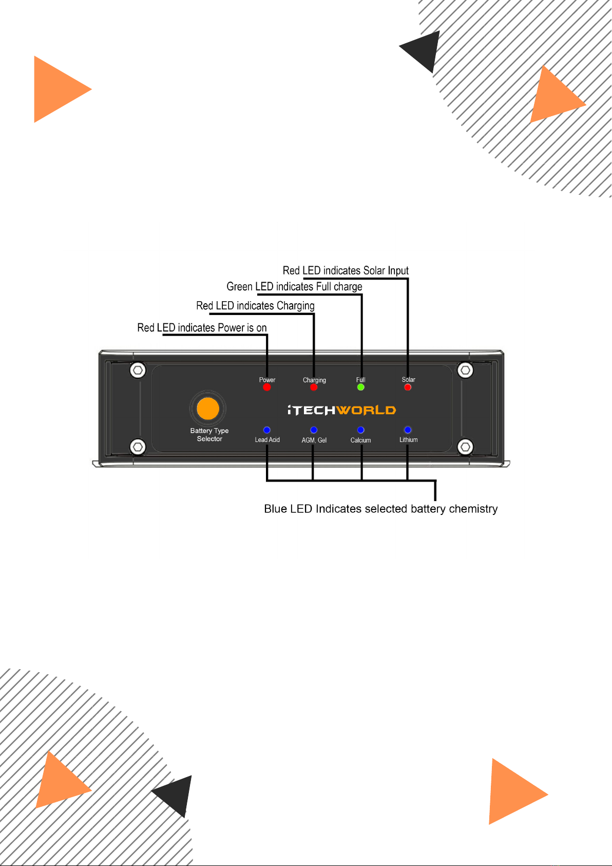
The initial default setting is for AGM/GEL batteries.
If you are charging a battery of different chemistry,
simply change the battery type by unplugging the aux
battery, then press the battery type selector button on
the front panel of the iTECHDCDC40 and reconnect the
aux battery.
Once you have selected the new battery type the
iTECHDCDC40 will remain on this battery type until it is
changed. To change battery type the auxiliary battery
must be disconnected from the iTECHDCDC40. This is a
safety feature to stop you accidentally changing the
battery charge profile.
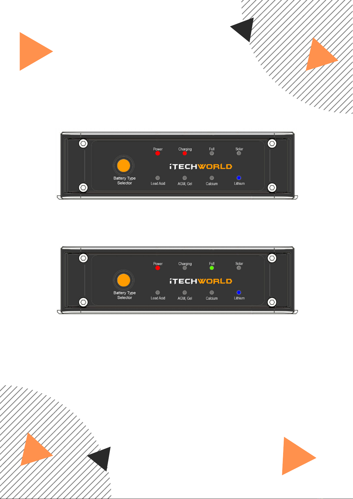
The iTECHDCDC40 will continue to operate even after the
vehicle has been switched off, however, once the main
starting battery falls to 12.4v the iTECHDCDC40 charger
will automatically switch off. If a solar panel is connected
the iTECHDCDC40 will now switch to solar.
DC BATTERY
Once correctly installed, the iTECHDCDC40 is a simple set
and forget system.
OPERATING THE ITECHDCDC40
USER GUIDE