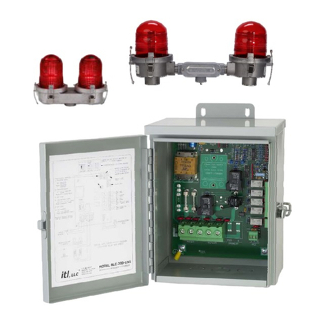
ITL RLC-0201-UNI User manual

Toll Free: +1 (866) 624-8309 www.itl-llc.com
Installation
and
Operation
Manual
RLC-0201-
UNI/GUI
Universal
LED & Incandescent
A-1 Controller

RLC-201
DOC-RLC201-MNL Rev10.doc (12/18/2020) Copyright 1999-2020 ITL, LLC Page 2 of 15
Front Matter
Copyright & Trademarks
Copyright © 1999-2020 by ITL, LLC. All rights reserved. This document contains
proprietary information, photographs, graphics, and other material (collectively, "the
Content") protected by copyright, and this manual and all accompanying hardware,
software and documentation are copyrighted. No part of this document may be
photocopied or reproduced by mechanical, electronic, or other means in any form without
written consent of ITL, LLC.
ITL, LLC and the ITL logo are trademarks of ITL, LLC. All other trademarks and brand
names are the property of their respective proprietors.
Limited Warranty and Disclaimer
ITL, LLC guarantees that every RLC-201 series controller is free from physical defects of
material and workmanship under normal use for one (1) year from the date of purchase.
If the product proves defective during this warranty period, please contact ITL, LLC in
order to obtain a Return Authorization Number, RMA.
In no event shall ITL, LLC’s liability exceed the price paid for the product from direct,
indirect, special, incidental, or consequential damages resulting from the use of the
product, its accompanying software, or its documentation. ITL, LLC makes no warranty
or representation, expressed, implied, or statutory, with respect to its products or the
contents or use of this documentation and all accompanying software, and specifically
disclaims its quality, performance, merchantability, or fitness for any particular purpose
unless otherwise stated.
The technical documentation is being delivered to you AS-IS. ITL, LLC makes no
warranty as to its accuracy or use. Any use of the technical documentation or the
information contained therein is at the risk of the user. Documentation may include
technical or other inaccuracies or typographical errors. ITL, LLC reserves the right to
revise or update its products, software, or documentation without obligation to notify any
individual or entity.
Please send any comments regarding the manual to [email protected].

RLC-201
DOC-RLC201-MNL Rev10.doc (12/18/2020) Copyright 1999-2020 ITL, LLC Page 3 of 15
Safety Warning
This equipment uses lethal voltages which can cause serious injury and/or death. Do not
attempt to service this equipment with line power applied.
Do not rely on interlock switches to remove lethal voltages from the system. Measure for
voltages using a voltmeter to ensure that power is off and has been completely removed.
Do not wear any jewelry. Gold and silver are excellent conductors of electricity.

RLC-201
DOC-RLC201-MNL Rev10.doc (12/18/2020) Copyright 1999-2020 ITL, LLC Page 4 of 15
Table of Contents
Front Matter ....................................................................................................................... 2
Copyright & Trademarks ................................................................................................ 2
Limited Warranty and Disclaimer ................................................................................... 2
Safety Warning .............................................................................................................. 3
Introduction ........................................................................................................................ 5
Product Description ........................................................................................................... 5
Specifications .................................................................................................................... 6
Environment ................................................................................................................... 6
Obstruction Lights .......................................................................................................... 6
Mechanical ..................................................................................................................... 6
Electrical ........................................................................................................................ 6
Installation ......................................................................................................................... 7
Unpacking your RLC-201 Controller .............................................................................. 7
Quick Installation Guide ................................................................................................. 7
RLC-201 Controller Mounting ........................................................................................ 8
Electrical Connections ................................................................................................... 9
Connector Descriptions ................................................................................................ 10
Setup and Operation ....................................................................................................... 11
Configuration Jumpers ................................................................................................. 12
Configuration Switches ................................................................................................ 12
Marker Alarm Setting ................................................................................................... 13
Manual Mode Select Switch ......................................................................................... 13
Indicator Lights............................................................................................................. 13
Spare Parts & Replacement Parts ................................................................................... 14
Technical Support and Contact Info ................................................................................ 15
Contact Info ................................................................................................................. 15
RMA ............................................................................................................................. 15

RLC-201
DOC-RLC201-MNL Rev10.doc (12/18/2020) Copyright 1999-2020 ITL, LLC Page 5 of 15
Introduction
Congratulations! You have purchased one of the most advanced control solutions for red
LED and incandescent obstruction lighting systems available today. This product is the
result of many years of engineering with extensive input from field service personnel.
Please take the time to read and familiarize yourself with this manual. It contains the
information necessary to install, test and troubleshoot the RLC-201.
Product Description
Both the RLC-0201-UNI and RLC-0201-GUI are capable of controlling one FAA type L-
864(L) red LED or FAA type L-864 incandescent beacon and up to five FAA type L-810(L)
red LED or FAA type L-810 incandescent markers. Individual alarm relays are provided
for indication of beacon lamp alarm, flasher fail, marker alarm, and system mode.
Virtually all information necessary for installation and operation of the RLC-201 is
available on the “quick info” card located in the door of the enclosure. The RLC-0201-GUI
utilizes a GPS to provide wireless flash synchronization with other RLC-0201-GUI units.
.
RLC-201-UNI
RLC-201-GUI

RLC-201
DOC-RLC201-MNL Rev10.doc (12/18/2020) Copyright 1999-2020 ITL, LLC Page 6 of 15
Specifications
Designed to comply with AC 150/5345-43 and ICAO Annex14
Environment
Temperature -40ºC to +55ºC
Humidity less than 95% relative humidity (non-condensing)
Obstruction Lights
Beacon One Incandescent Beacon
two 620W/120 Vac lamps or
two 700W/230 Vac lamps
One ITL IFH-1900 or
One ITL IFH-1700 or
One Dialight D564 Series LED Beacon or
One Dialight D464 Series LED Beacon or
One Dialight D264 Series LED Beacon
Side Lights Up to Five Incandescent
116W or 100W, 120 or 230 Vac
Up to Five LED
ITL-MKR-LTG1-0IR or
ITL MKR-LTE1-000, MKR-LTE1-0IR
or Dialight MKR-0LED-RTO-001
Mechanical
Dimension Height: 12.00” (305mm)
Width: 8.81” (224mm)
Depth: 7.00” (177mm)
Weight 8 lbs (3.6Kg)
Electrical
Input Power 120/230 VAC at 50/60Hz, 6VA
Alarm Relays: 120/230 VAC, 1 Amp
PEC: 120/230 Vac, 50/60 Hz, 1 VA
Suppression 320 Joule, 275V, Input Power, Beacon,
Side Lights & PEC
23 Joule, 275V, All alarm relays

RLC-201
DOC-RLC201-MNL Rev10.doc (12/18/2020) Copyright 1999-2020 ITL, LLC Page 7 of 15
Installation
The following section describes how to install the RLC-201 controller. The Incandescent
Beacon or LED Beacon, and Obstruction Lights (markers) should be installed according
to the manufacturer’s instructions.
Unpacking your RLC-201 Controller
Please examine the shipping containers and their content thoroughly upon receipt and
report any potential shipping damage to the carrier.
Quick Installation Guide
The quick start guide shows how to install the RLC-201 controller.
Remove RLC-201 controller from packaging material.
Mount the RLC-201 enclosure.
Install FAA type L-864 Incandescent Beacon or FAA type L-864(L) LED Beacon
per manufacturer’s instructions and FAA requirements.
Install electrical cable from RLC-201 to Incandescent Beacon or LED Beacon per
manufacturer’s instructions.
Install FAA type L-810 incandescent or FAA type L-810(L) type LED obstruction
lights per manufacturer’s instruction and FAA requirements.
Install cable from RLC-201 to L-810 obstruction lights (markers) per
manufacturer’s instructions.
Install Photoelectric Cell and socket (ITL P/N: PEC-1800-120, PEC-SOCK-000).
Install GPS Antenna (RLC-201-GUI only)
Install 120Vac line power to the RLC-201 Controller.

RLC-201
DOC-RLC201-MNL Rev10.doc (12/18/2020) Copyright 1999-2020 ITL, LLC Page 8 of 15
RLC-201 Controller Mounting

RLC-201
DOC-RLC201-MNL Rev10.doc (12/18/2020) Copyright 1999-2020 ITL, LLC Page 9 of 15
Electrical Connections
All electrical control connections are made on P1, P2, P3 and P4 located at the bottom of
the controller. Connections for alarm relays are made on P5 and P6 located on the right
side of the controller. Typical connections for a 120VAC system are shown below.
It is the responsibility of the installer to comply with all applicable local,
state, and federal regulations for installation and operation of this device.

RLC-201
DOC-RLC201-MNL Rev10.doc (12/18/2020) Copyright 1999-2020 ITL, LLC Page 10 of 15
Connector Descriptions
Connector Terminals Function
P1 L1
N
Input Power Line Voltage
Input Power Neutral
P2 PRI
N
SEC
Primary Beacon
Power Supply Neutral
Secondary Beacon
P3 MKR
N
Marker Light Power (L-810 obstruction light power)
Marker Light Neutral
P4 BLK
WHT
RED
Photoelectric Cell Line Power
Photoelectric Cell Neutral
Photoelectric Cell Signal (120Vac=Night, 0Vac=Day).

RLC-201
DOC-RLC201-MNL Rev10.doc (12/18/2020) Copyright 1999-2020 ITL, LLC Page 11 of 15
Setup and Operation
Setup and operation of the RLC-201 is performed using the Configuration Jumpers,
Configuration DIP Switches, the Marker Alarm Setting dial, and the Manual Mode Select
Switch.
Configuration
Jumpers
Manual Mode
Select Switch
Configuration
DIP Switches
Marker Alarm
Setting
Alarm
Contacts
GPS Connection
RLC-201-GUI only

RLC-201
DOC-RLC201-MNL Rev10.doc (12/18/2020) Copyright 1999-2020 ITL, LLC Page 12 of 15
Configuration Jumpers
The configuration jumpers must be set to match the type of obstruction lights used with
the RLC-201 controller. Jumper settings for typical markers are shown in the figure
below. Contact the factory if your model lights are not shown.
Configuration Switches
SW1 - Configuration Switches
Number Description Function
1 Backup Enable ON – Backup Beacon Enabled
OFF* – Backup Beacon Disabled
2 Backup Alarm ON – K7 is Beacon Backup Alarm
OFF* – K7 is Mode Relay
3 Marker Alarm
Disable
ON – Marker alarm is disabled.
OFF* – Marker alarms is enabled.
4 Beacon Type 1 ON – ITL IFH-1900 or Dialight D464 or D564
5 Beacon Type 2 ON – ITL IFH-1700 or Dialight D264
6 Marker Type See Marker Configuration Jumpers above
* The factory default setting for all switches is OFF
SW4 - Configuration Switches
Number Description Function
1 Phase 1 Used to synchronize flashing with other
manufacturers GPS synchronized controllers.
(RLC-0201-GUI only) Default is both OFF
2 Phase 2
3 Not Used
4 Flash Rate 30
FPM
ON – Flash rate is 30 FPM
OFF* – Flash rate is 20 FPM
* The factory default setting for all switches is OFF
Note: This manual is subject to change without notice. Refer to the diagram in the door
of the RLC-201 or the manual shipped with the RLC-201 for setup and configuration
information.

RLC-201
DOC-RLC201-MNL Rev10.doc (12/18/2020) Copyright 1999-2020 ITL, LLC Page 13 of 15
Marker Alarm Setting
The Marker Alarm Setting switch sets the number of marker lamps at which a marker
alarm will be generated. The switch is adjustable from zero to four lamps. The factory
default setting is one, meaning that a marker alarm will be generated when one or less
marker lamps are burning.
Manual Mode Select Switch
The Manual Mode Select Switch overrides the photoelectric cell (PEC) to allow selection
of Day mode or Night Mode for test or troubleshooting purposes. The Day or Night Mode
lights flash when in manual mode. This switch should be left in the AUTO position for
normal operation. In the AUTO position the operating mode is determined by the
photoelectric cell.
Indicator Lights
Indicator Lights
Description Function
DAY MODE Steady – Day mode operation via photoelectric cell.
Flashing – Day mode operation via manual mode select switch.
NITE MODE Steady – Night mode operation via photoelectric cell.
Flashing – Night mode operation via manual mode select switch.
CMD On when the RLC-201 commands the beacon to flash.
CONF On when the RLC-201 confirms that the beacon is drawing the
correct current.
BCN ALM Steady – Indicates a beacon lamp alarm.
Flashing – Indicates a flasher fail alarm (K3)
MKR ALM Indicates a marker alarm.
PEC ALM Indicates a photoelectric cell alarm
(controller defaults to night mode on PEC alarm)
BU ALM Indicates that the RLC-201 is operating the backup beacon.
FIX Steady – Indicates the RLC-0201-GUI is receiving flash
synchronization data from GPS.
Flashing – Indicates the RLC-0201-GUI is waiting for flash
synchronization data from the GPS.
PPS Provides visual indication of the pulse per second signal from the
GPS.

RLC-201
DOC-RLC201-MNL Rev10.doc (12/18/2020) Copyright 1999-2020 ITL, LLC Page 14 of 15
Spare Parts & Replacement Parts
ITL Part Number Description
RLY-2440-B00 Solid State Relay
BCN-0300-000 L-864 Beacon, (Incandescent)
IFH-1900-0IR L-864(L) Beacon, (LED with Infrared)
IFH-1700-000 L-864(L) Beacon, (LED)
MKR-S750-0DH L-810 Obstruction Light, (Incandescent)
MKR-LTG1-0IR L-810(L) Obstruction Light, (LED with Infrared)
MKR-LTE1-000 L-810(L) Obstruction Light, (LED)
MKR-LTE1-0IR L-810(L) Obstruction Light, (LED with Infrared)
LMP-620W-120-LL 620W, 120VAC Beacon Lamp
LMP-700W-230 700W, 230VAC Beacon Lamp
LMP-116W-125-DUR 116W, 125-130VAC Marker Lamp
LMP-116W-230 116W, 230VAC Marker Lamp
ANT-018X-GPS GPS Antenna
PEC-1800-120 Photoelectric Cell (PEC)
PEC-SOCK-000 Socket For Photoelectric Cell

RLC-201
DOC-RLC201-MNL Rev10.doc (12/18/2020) Copyright 1999-2020 ITL, LLC Page 15 of 15
Technical Support and Contact Info
Contact Info
For information on the RLC-201 controller’s basic functions, refer to this manual. For
additional help with the installation or operation of any ITL products, please contact ITL,
LLC at one of the following below.
Web and Internet Sites
Corporate home page: http://www.itl-llc.com
Customer Support Technicians
8:00 AM - 5:00 PM Central Time
US and Canada call: +1-615-256-6030
Toll Free: +1-866-624-8309
RMA
Please contact ITL, LLC before returning equipment for repair and obtain a Return
Material Authorization (RMA) number.
Revision Description of Change Date Preparer / Approval
10 Updated board layout pg. 9 & pg11. Updated
Jumper configuration, added IFH-1900 & LTG.
Updated Spare Parts & Replacement Parts List.
12/18/2020 Prepared By: Elke Hinson
Approved By: Josh Crown
9 Updated Suppression data from 45 Joule to 320
Joule. Updated Spare Parts & Replacement Parts
List.
6/13/2017 Prepared By: Elke Hinson
Approved By: Andy Rudolph
8 Added D564 in configuration jumper table. 1/20/2016 Prepared By: Elke Hinson
Approved By: Andy Rudolph
7 Updated for quick info card changes 5/28/2015 Prepared By: Elke Hinson
Approved By: Andy Rudolph
6 Updated configuration jumpers and SW1 -
configuration switches
12/18/2012 Prepared By: Elke Hinson
Approved By: Andy Rudolph
5 Updated cover sheet,
Changed FAA Type for LED marker to L-810(L),
Changed FAA Type for LED beacon to L-864(L),
Added Jumper configuration for Dialight D464
series.
7/02/2012 Prepared By: Elke Hinson
Approved By: Andy Rudolph
This manual suits for next models
2
Table of contents
Other ITL Controllers manuals
Popular Controllers manuals by other brands

Siemens
Siemens ACR12.3 1 Series manual

Contemporary Research
Contemporary Research ICC2-VDC product manual

Radius
Radius EW 350 Installation, maintenance and operation manual

JUMO
JUMO 709062/8-01-50 operating manual

Prince Castle
Prince Castle HPC-1SNCA Operation manual

Homematic IP
Homematic IP HmIP-DRDI3 Installation and operating manual