ITRON 60WP Endpoint User manual

Water Solutions
60WP Endpoint Installation Guide
Water Solutions

Identification
60WP Endpoint Installation Guide
Part number: PUB-0771-002 Revision 003
Copyright
© 2005-2008 Itron, Inc. All rights reserved.
Your company has the right to reproduce this contract document, provided that such reproduction shall be subject to the same use and disclosure restrictions contained in the
Confidentiality and Non-Disclosure paragraphs in the Sales Contract.
Trademark Notice
Itron is a registered trademark of Itron, Inc.
All other product names and logos in this documentation are used for identification purposes only and may be trademarks or registered trademarks of their respective companies.
Patent Notice
US and foreign patents pending
Compliance Statement
This equipment has been tested and found to comply with the limits, pursuant to Part 15 of the FCC Rules. These limits are designed to provide reasonable protection against harmful
interference in a residential installation. Operation is subject to the following conditions:
•This device may not cause interference.
•This device must accept any interference that may cause undesired operation of the device.
Complies with IC: R.S.S.-210
Transportation Classification
The Federal Aviation Administration prohibits operating transmitters and receivers on all commercial aircraft. When powered, endpoints are considered operating transmitters and
receivers and cannot be shipped by air. All product returns must be shipped by ground transportation.
Repairs and Modifications
WARNING! Attempts to repair this device by unauthorized personnel may subject the person to shock hazard if removal of protective covers is attempted. Unauthorized repair may void
the warranty and/or maintenance contract with your company.
WARNING! This unit cannot be modified and is not repairable. Modification of this device could cause non-compliance with FCC rules. Attempts to modify this device will void the
warranty.
Lithium Batteries
WARNING! Follow these procedures to avoid injury to yourself or others:
•The lithium battery may cause a fire or chemical burn if it is not disposed of properly.
•Do not recharge, disassemble, heat, or incinerate the lithium battery.
•Keep the lithium battery away from children.
Support
If you have questions or comments about this product, contact Itron Technical Support:
North America
•E-mail: [email protected]
•Phone: 1 800 635 8725
Australasia
•E-mail: [email protected]
•Phone within Australia: 1 800 246 377
•Phone outside Australia: 61 2 9299 5744
International
•E-mail: [email protected]
•Phone: +31 20 60 65 220
Web Support
http://eKnowledge.itron.com
Itron Website
http://www.itron.com
Suggestions
If you have comments or suggestions on how we may improve this documentation, send them to TechnicalCommunicationsManager@itron.com.
Document Revision
The content of this publication was last edited on 5/23/2008.

Water Solutions 60WP Endpoint Installation Guide iii
Before You Begin ..........................................................................................................v
How This Document is Organized.......................................................................................................v
Documentation Conventions..............................................................................................................vi
Chapter 1 About the 60WP Endpoint..........................................................................7
Battery Life ..........................................................................................................................................7
Installation Options..............................................................................................................................7
Operating Modes.................................................................................................................................8
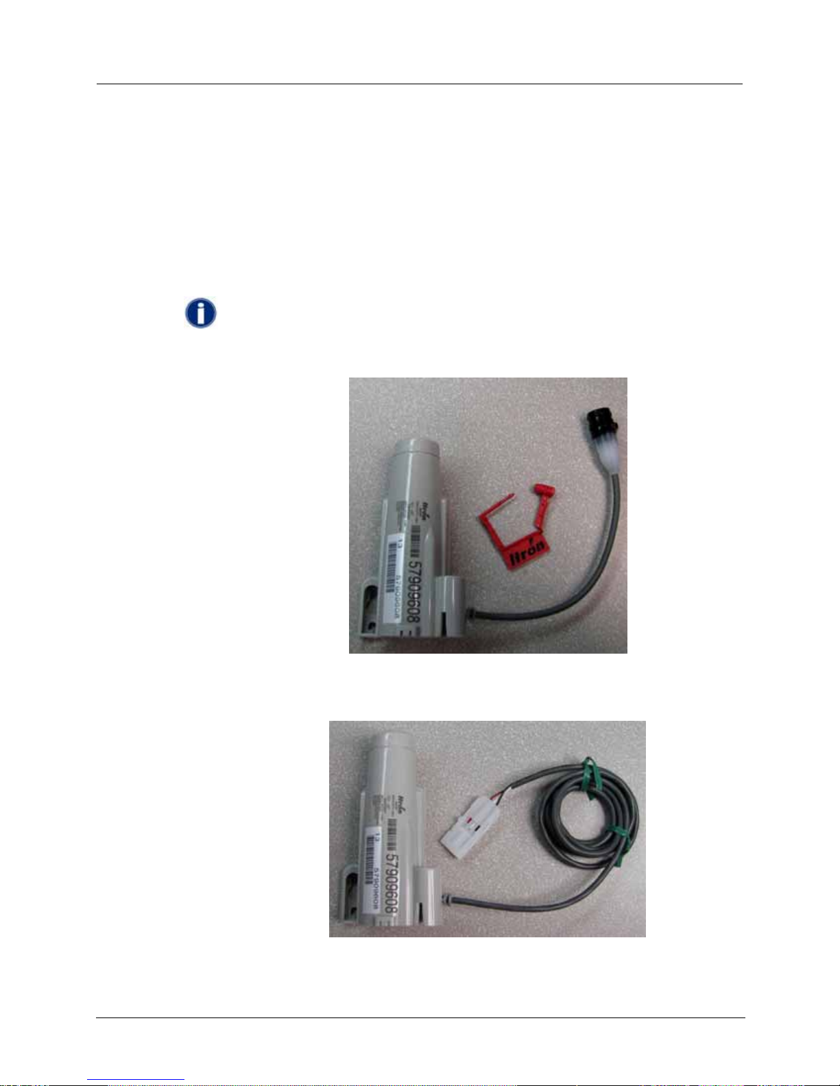
Included Materials...............................................................................................................................9
Accessories.......................................................................................................................................10
Installation Process Overview...........................................................................................................10
Chapter 2 Installing the 60WP Endpoint...................................................................11
Rod Mount Installation.......................................................................................................................11
Required Tools and Hardware - Rod Mount Installation.........................................................11
Wall Mount Installation......................................................................................................................16
Required Tools and Hardware - Wall Mount Installation........................................................16
Installing Using a Wall Mount..................................................................................................16
Through-Lid Mounting.......................................................................................................................18
Pit Lids with Holes...................................................................................................................18
Required Tools and Hardware......................................................................................18
Installing Through New Lid .....................................................................................................20
Required Tools and Hardware......................................................................................21
Shelf Mount Installation.....................................................................................................................23
Required Tools and Hardware................................................................................................24
Chapter 3 Connecting the 60WP ...............................................................................27
Using an Inline Connector.................................................................................................................27
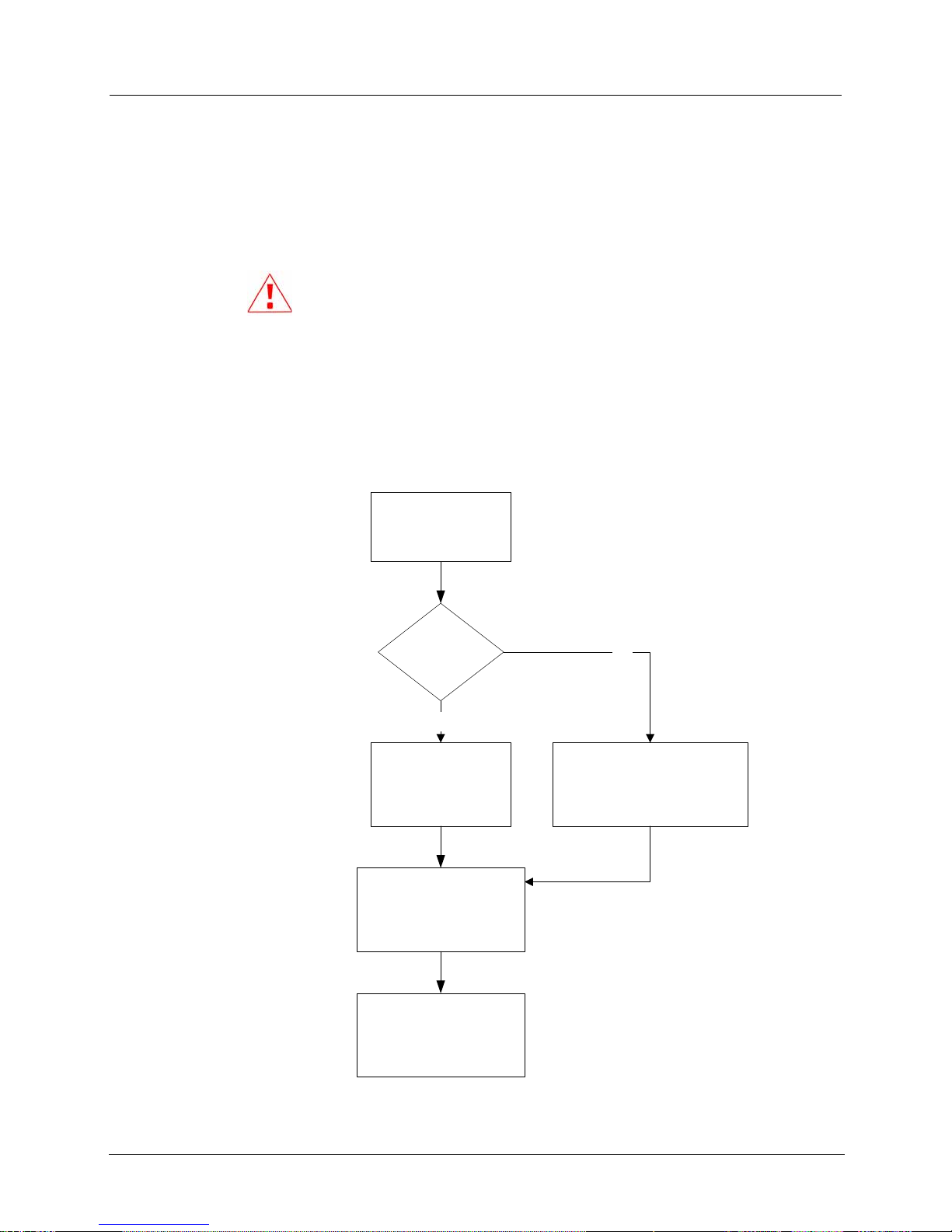
Using a 5-Foot Cable ........................................................................................................................29
Using an Extended Cable..................................................................................................................30
Chapter 4 Programming and Verifying 60WP Endpoint Operation........................31
Activating Programming Mode..........................................................................................................31
Programming the 60WP Endpoint.....................................................................................................32
Verifying Operation of the 60WP Endpoint .......................................................................................34
Contents

Contents
iv Water Solutions 60WP Endpoint Installation Guide

Water Solutions 60WP Endpoint Installation Guide v
This document describes the installation of the 60WP Endpoint for rod mount, wall mount,
through-lid, and shelf mount installations. The 60WP Endpoint is available in the following
cable configurations:
•Inline connector with approximately six inches of cable
•5-foot open-end cable
•6-inch open-end cable
These cable combinations allow easy interface to several types of pulser meter registers.
The 6-inch cable variant allows meter manufacturers to integrally mount the endpoint to
their respective meter registers. When installing a meter register in a water pit box that is
configured in this manner, it is important to recognize that the distance from which the
endpoint's radio signal can be detected will be significantly reduced as the meter is located
deeper in the pit box. When a point is reached where read reliability is compromised, a new
installation method must be selected.
How This Document is Organized
This document is organized as shown in the following table.
Chapter Description
Before You Begin Provides information about this publication.
About the 60WP Endpoint Gives an overview of the 60WP endpoint installation,
including installation options, positioning, and required
tools.
Installing the 60WP Endpoint Provides step-by-step instructions for installing the
endpoint using the rod mount, wall mount, through lid
mount, or pit lid shelf mount.
Connecting the Endpoint to the Register Provides information about wiring the endpoint to a
register using the inline connector, a 5-foot cable, or an
extended cable.
Programming the 60WP Endpoint Describes how to activate programming mode,
program the endpoint, and verify operation of the
endpoint.
CHAPTER
Before You Begin

Before You Begin
vi Water Solutions 60WP Endpoint Installation Guide
Documentation Conventions
The following documentation conventions are used in this guide:
Convention Example
Itron product part numbers are noted in
parentheses. To install the endpoint (ERW-0771-3XX), perform the
following steps.
Hypertext links are in blue. See Installation Process Overview on page 10 for a
diagram of the installation process.
WARNING! This type of note is used to warn of potential physical harm
to the user or hardware. It is critical that you pay strict attention to
WARNING notes, read the information carefully, and heed the advice
and instructions.
CAUTION! This type of note warns the user that failure to head the
information in the note could result in loss of data. Be sure to carefully read
a CAUTION note and heed the advice/instructions.
NOTE! This type of note provides additional information to the user.

Water Solutions 60WP Endpoint Installation Guide 7
The 60WP Endpoint is an Automatic Meter Reading (AMR) module that collects
consumption and tamper information and reports in a bubble-up fashion. Approximately
every seven seconds, the 60WP Endpoint transmits a standard consumption message (SCM)
at approximately +10dBm (10 milliwatts) between 910-920 MHz.
The 60WP Endpoint supports protocols for a variety of meter manufacturer's registers,
including but not limited to AMCO, Badger, Sensus and Actaris registers. Refer to Itron
part number PUB-0063-002, Water Meter Compatibility List, for the list of meter
manufacturers currently supported.
The 60WP Endpoint features the following capabilities:
•Leak Detection–The 60WP Endpoint indicates by meter reading software that a
potential system leak exists if a zero consumption value does not occur over a seven
day period of hourly register reads. Upon detecting a zero consumption the leak
message will be changed to an "Off" status and the seven day test period will be reset.
•Tamper Indicators–To minimize the possibility of theft, the 60WP Endpoint features
cut cable tamper reporting as well as a security seal to indicate physical tampering. A
cut cable tamper is reported when the cable connecting the register and endpoint has
been cut or disconnected. The tamper indicator will continue incrementing until the
problem has been resolved.
Battery Life
Powered by a non-replaceable long life dual lithium battery pack, the 60WP Endpoint has
an expected battery life of approximately 15 years.
Installation Options
The 60WP Endpoint can be installed using the following methods:
•Rod Mount–Rod mount installation allows the endpoint to be mounted on a 1/2 inch
outside diameter rod.
•Wall Mount–Wall mount installation attaches the endpoint to a wall or other vertical
surface within a meter pit.
•Through Lid–Requires the pit lid mounting kit, enabling the endpoint to be mounted
in lids with hole sizes from 1 3/4 inches to 2 inches. This method is used for passive
radiator antenna applications.
•Shelf Mount–Used in conjunction with the shelf mount adaptor, this option allows the
endpoint to slide into a pit lid slot.
CHAPTER 1
About the 60WP Endpoint

Chapter 1 About the 60WP Endpoint
8 Water Solutions 60WP Endpoint Installation Guide
Generally, for water pit boxes, the type of installation method chosen will be based on two
factors: the type of lid material and the current lid configuration. Metal lids usually require a
through-lid solution for optimal endpoint radio performance. Plastic lids and other
composite materials are acceptable for any of the installation methods described above with
some lids having an underneath shelf design.
NOTE For the shelf mount option, the pit lid slot must be the correct dimensions
for the 60WP Endpoint assembly to fit. Evaluate each type of pit lid to determine
the proper installation option. See Shelf Mount Installation on page 23 for more
information.
Operating Modes
The 60WP Endpoint provides the following operating modes:
•Programming Mode - Use the programming magnet (Itron part number MSE-0159-003)
to activate the unit and put it into Programming Mode. The 60WP Endpoint stays in
Programming Mode for 15 minutes. For the location of the magnet see Activating
Programming Mode on page 31.
NOTES!
•Hold the magnet in position for three seconds to activate
Programming Mode. If it is held there longer than 15 minutes,
you must remove the magnet for three seconds and then put it
back into position to reactivate Programming Mode.
•You must activate Programming Mode in the 60WP Endpoint to
verify operation. For more information see Verifying Operation
of the 60WP Endpoint on page 34.
•Normal Mode - Following the 15-minute Programming Mode, the endpoint goes into
Normal Mode and begins to operate as programmed.
•Quiet Mode - In Quiet Mode the endpoint turns off its transmitter and receiver
functions. The unit can be put into Normal Mode by adding counts to the attached
register or into Programming Mode using the magnet.
•Off Mode - The 60WP Endpoint is shipped in Off Mode. In Off Mode the unit does
nothing unless activated by a magnet for programming.
You can program the 60WP Endpoint using an FC200SR handheld computer running the
Endpoint-Link software. For more information about programming the endpoint, see
Programming the 60WP Endpoint on page 32.

Included Materials
Water Solutions 60WP Endpoint Installation Guide 9
Included Materials
The following materials are supplied by Itron:
•60WP Endpoint with inline connector, protective cover for inline connector, and
tamper seal for security - (ERW-0771-301) (Figure 1)
OR
•60WP endpoint with a 5-foot cable - (ERW-0771-311) (Figure 2)
NOTE! The 6-inch cable variant is only available to meter manufacturers and,
therefore, installation for this model is not covered in this document.
Figure 1: 60WP Endpoint with Inline Connector and Tamper Seal
Figure 2: 60WP Endpoint With 5-Foot Cable

Chapter 1 About the 60WP Endpoint
10 Water Solutions 60WP Endpoint Installation Guide
Accessories
The following additional materials may be needed depending on your type of installation.
•Cable Ties (15-inch for indoor pipe mounting installation) - Itron part number CFG-
0771-003 (Qty 72)
IMPORTANT! These cable ties are not intended to be used for
mounting the 60WP in an outdoor or pit box environment. Use Panduit
PLT4H-76 (or equivalent) cable ties for outdoor and pit box applications.
•Through-Lid Mounting kit - Itron part number CFG-0771-010 (Minimum order: 36)
•Shelf Mount Adaptor - Itron part number CFG-0771-007 (Minimum order: 36)
Installation Process Overview
The process for installing a 60WP Endpoint is illustrated below.
Mount
60WP endpoint
Is inline
connector
used?
Connect
inline connector
Use magnet to put
endpoint into
programming mode and
program endpoint
Verify 60WP operation
No
Yes
Mount register according
to manufacturer's
recommended procedure

Water Solutions 60WP Endpoint Installation Guide 11
This chapter shows you how to install the 60WP endpoint. Use one of the following
procedures to mount the 60WP endpoint:
•Rod Mount Installation on page 11
•Wall Mount Installation on page 16
•Through-Lid Mounting on page 18
•Shelf Mount Installation on page 23
Rod Mount Installation
The 60WP endpoint can be mounted below the pit lid on a customer-supplied rod. The
example installation described in this section utilizes a 1/2-inch fiberglass rod. For supplier
information on the rod material, see information under Compatibility Chart at the following
Itron website address:
www.itron.com/pages/products_detail.asp?ID=itr_000428.xml&pgtype=&subID=ar
WARNING! You must ensure that the area where the rod will be installed is
free from other pipes, wires, or facilities that may be damaged by driving a rod
into the ground.
CAUTION! You must follow local codes when using the rod mount installation
method.
Required Tools and Hardware - Rod Mount Installation
The following items are required for the rod mount installation:
•Hammer
•3/8-inch to 1/2-inch outside diameter rod (1/2-inch diameter is preferred for new
installations)
•Tape measure
•Cutting tool for adjusting rod length
CHAPTER 2
Installing the 60WP Endpoint

Chapter 2 Installing the 60WP Endpoint
12 Water Solutions 60WP Endpoint Installation Guide
The following figure shows a bottom view of the rod mount. The 1/2-inch diameter rod hole
is indicated in the photo.
Figure 3: Rod Mount, Bottom View
The following figure shows a side view of the rod mount, also indicating the 1/2-inch
diameter rod hole.
Figure 4: Rod Mount, Side View

Rod Mount Installation
Water Solutions 60WP Endpoint Installation Guide 13
To install using a rod mount
1. Remove the pit lid. Inspect the area to make sure there are no buried cables, pipes, or
other obstructions.
2. Measure the depth of the pit box from the top of the lip on which the lid will rest to
the bottom of the pit. Be sure to measure the depth at the point where the rod will be
driven into the ground.
3. Add 12 inches to the pit box depth measurement taken in step 1.2. The resulting total
represents the minimum length of rod needed. Soil types and moisture conditions may
require longer rod lengths to ensure the endpoint is well supported and remains
vertical.
4. Without touching the meter body or adjacent pipes, position the rod as close to the
center of the pit as possible, and then drive it into the ground.
Ensure that the rod remains vertical.
5. Drive the rod into the ground to a depth that achieves dimension A in the illustration
below.
•If rod cannot be driven in sufficiently to achieve the 5 3/4 inch spacing, cut the
remaining rod length to the proper height by using an abrasive cut off tool.
•If the rod is driven to the correct depth but remains loose in the soil the rod
should be replaced with a longer version.
CAUTION! When cutting fiberglass, use proper safety precautions when using
cut-off tools and to prevent exposure to fiberglass dust particles.

Chapter 2 Installing the 60WP Endpoint
14 Water Solutions 60WP Endpoint Installation Guide
6. Place the endpoint onto the rod, making sure the rod is completely seated into the Rod
Mount hole of the endpoint. The endpoint should slide freely onto the rod; it should
not be forced.
7. When the installation is complete the endpoint should be perpendicular to the
underside of the lid. The endpoint should not contact the pit structure or lid.

Rod Mount Installation
Water Solutions 60WP Endpoint Installation Guide 15
CAUTION! If the endpoint module installation is too high, too low, or touching any
of the surrounding surfaces, then adjust as necessary.

Chapter 2 Installing the 60WP Endpoint
16 Water Solutions 60WP Endpoint Installation Guide
Wall Mount Installation
For locations other than a water pit box, select a flat vertical mounting surface. Install the
endpoint in an upright position, ensuring that the arrow on the endpoint label is pointing
upward. Mounting the unit in an upside-down orientation will shorten battery life.
To mount the endpoint to a water pit box, select a mounting location on the inside the pit
box and try to maintain a distance of one to three inches from the bottom of the pit box lid.
NOTE For cable lengths exceeding 150 feet, see Connecting With an Extended
Cable.
Required Tools and Hardware - Wall Mount Installation
The following items are required for a wall mount installation:
•Drill and drill bits for expected pit box material.
•Common hand tools for the type of fastening method selected.
•Mounting screws. Select a #10 size pan head screw that is appropriate for the type of
box material.
Installing Using a Wall Mount
To install the 60WP Endpoint using the wall mount method, mount the endpoint on the pit
box wall so that the top of the endpoint is between one and three inches below the bottom of
the lid.
Always mount the endpoint in a vertical position. When mounting to a curved surface, such
as a round pit box, only tighten the mounting screws to a point where the endpoint is secure.
Over-tightening could fracture the plastic mounting tabs.
CAUTION! When using the wall mount method, be careful not to over-tighten the
mounting screws; the mounting tabs on the endpoint may break as a result.
Procedure
1. Select a vertical surface in the meter box.
2. Position the endpoint vertically and approximately 1 inch from the top of the lid lip
and mark location of top mounting hole.
3. Pre-drill a pilot hole in the pit box wall. Follow the screw manufacturer's
recommendation to determine the size of the pilot hole.
4. For concrete-type pit boxes, it may be necessary to use a screw anchor. Choose an
anchor that will accommodate a #10 pan head screw.

Wall Mount Installation
Water Solutions 60WP Endpoint Installation Guide 17
5. Start a screw into the pilot hole. Using the top hole of the endpoint, set the endpoint
over the screw head and slide it down so the screw is now at the top of the notch as
shown below. Tighten the screw until snug. Do not over tighten as this could
potentially crack the endpoint housing.
6. Keeping the 60WP endpoint in the upright position, drill the second pilot hole using
the bottom mounting hole as a template.
NOTE! If using a screw anchor, mark the location of the bottom
anchor, remove the endpoint, drill the required hole, insert the anchor
and reattach the endpoint.
IMPORTANT! Any endpoint position other than upright may
negatively affect radio performance and battery life.
7. Screw the bottom screw into the pilot hole until snug.
IMPORTANT! Over tightening the screws may crack the endpoint
housing plastic around the screw.

Chapter 2 Installing the 60WP Endpoint
18 Water Solutions 60WP Endpoint Installation Guide
Through-Lid Mounting
This section describes mounting the 60WP Endpoint in a pit lid that has an 1 3/4-inch, 1
7/8-inch, or 2-inch round hole drilled through it.
CAUTION! Some pit lids have a molded, recessed cavity that allows Itron 40W-1,
50W-1, and 50W-2 ERT modules to sit flush with the top surface of the lid.
However, the dome of the endpoint retainer for the 60-series endpoints, and
passive radiator antenna, have a smaller diameter and do not fill the pit lid cavity.
This can make the cavity a trip hazard. Itron does not recommend using this type
of pit lid with the 60-series endpoints.
Pit Lids with Holes
This section describes how to install the 60WP Endpoint in a pit lid that already has a 1 3/4-
inch, 1 7/8-inch or 2-inch hole in the lid. The Pit Lid Mounting Kit or the Passive Radiator
Antenna Kit can be used for this application. This section will explain how to install both
types of kits. Please refer to publication PUB-0771-010 for guidance on which kit to install
for different pit lid material and traffic conditions.
NOTE For lids that require a hole to be drilled, see To install in new lids on page
21.
Required Tools and Hardware
•Pit lid mounting kit (Itron part number CFG-0771-010) or passive radiator antenna kit
(Itron part number CFG-0771-006)
•Cable tie gun
NOTE The pit lid mounting kit is not intended for applications involving
vehicular traffic. The passive radiator antenna should be used in incidental traffic
areas, such as residential environments.

Through-Lid Mounting
Water Solutions 60WP Endpoint Installation Guide 19
To install in lids with holes
1. Make sure you have all the following items to complete the installation.
A Retainer clip or passive radiator antenna
B Simulated pit lid
C Retainer clip collar
D 60WP Endpoint
E Cable ties
F O-ring spacer (not required for 1 3/4-inch holes)
2. Measure the diameter of the hole in the pit lid. If the hole diameter is 1 3/4-inch, an O-
ring spacer is not required.
3. For 1 7/8-inch or 2-inch holes place the appropriate O-ring spacer over the pit lid
mounting kit, or passive radiator antenna.
4. Insert the retainer clip, or passive radiator antenna, into the hole in the pit lid.
5. From the underneath side of the lid, place the retainer clip collar around the retainer
clip and snug the collar to the bottom side of the pit lid. Ensure that the top of the
retainer clip is seated against the lid surface as shown below.

Chapter 2 Installing the 60WP Endpoint
20 Water Solutions 60WP Endpoint Installation Guide
6. Secure the assembly with 2 cable ties (A).
7. Align and insert the top of the 60WP Endpoint into the offset cavity (A) of the retainer
clip, or passive radiator antenna, and push until it snaps into place.
The finished assembly is shown below.
Installing Through New Lid
This section describes how to install the 60WP Endpoint in a pit lid that does not have a
hole drilled through it.
NOTE For lids with holes already drilled, see Pit Lids with Holes on page 18.
Table of contents
Other ITRON Industrial Equipment manuals
Popular Industrial Equipment manuals by other brands

Grizzly
Grizzly T32716 instructions

Z.I.P.P.ER MASCHINEN
Z.I.P.P.ER MASCHINEN ZI-MHKT4 user manual

IOLINK
IOLINK BALLUFF BIS U-4A7-082-01C-07-S4 Configuration

SealerSales
SealerSales ST-1606-20-220V manual

Ebmpapst
Ebmpapst R1G133-AA17-02 operating instructions

FRONIUS
FRONIUS Energy Package operating instructions