ITS Telecom 1700264 User manual

September 29, 2020
MITS JANUS TIME ENGINE
PART NUMBER 1700264
OPERATION MANUAL

MITS Janus Time Engine
Page 2 of 39
Copyright© Instrumentation Technology Systems 2020 20200929
TABLE OF CONTENTS
CHANGE HISTORY ................................................................................................................................................... 4
1.0 GENERAL DESCRIPTION ............................................................................................................................ 5
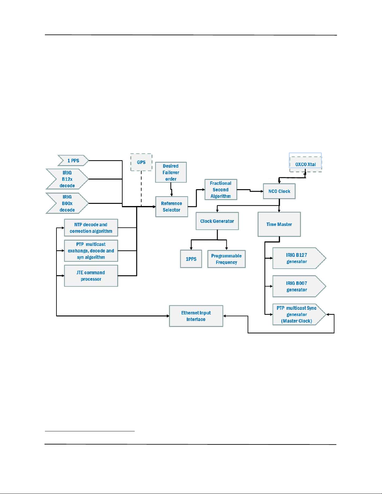
1.1 JANUS TIME ENGINE MASTER CONTROLLER (JTEMC) ................................................................................................. 5
1.1.1 Time Master .................................................................................................................................... 5
1.1.2 IRIG B Inputs .................................................................................................................................. 7
1.1.3 1PPS Inputs ..................................................................................................................................... 7
1.1.4 GPS Time Reference ....................................................................................................................... 8
1.1.5 PTPV2 Master Clock Function ....................................................................................................... 8
1.1.6 Time of Day Clock .......................................................................................................................... 9
1.1.7 Time Zone Offset ............................................................................................................................ 9
1.1.8 Ethernet ........................................................................................................................................... 9
1.1.9 Settings Flash ................................................................................................................................ 10
1.1.10 I/O Interface .................................................................................................................................. 10
1.2 PHOTO-SONICS INTERFACE (PSI/O) ...................................................................................................................... 11
1.2.1 Time code and frequency output ports .......................................................................................... 11
1.3 IRIG B TIME CODE GENERATOR ............................................................................................................................. 12
1.3.1 An IRIG B127 output buffer ......................................................................................................... 12
1.3.2 An IRIG B007 output buffer ......................................................................................................... 12
1.4 PROGRAMMABLE FREQUENCY GENERATORS ............................................................................................................ 12
1.4.1 Clock A ......................................................................................................................................... 12
1.4.2 Clock B ......................................................................................................................................... 12
2.0 NETWORK TIME SYNCRHONIZATION...................................................................................................... 12
2.1 NTP DECODE/CORRECTION ................................................................................................................................. 13
2.2 PTP SYNCHRONIZER ALGORITHM .......................................................................................................................... 13
3.0 WEBSERVER ........................................................................................................................................... 13
3.1 HOME PAGE ...................................................................................................................................................... 14
3.1.1 Time frame .................................................................................................................................... 14
3.2 ADMIN PAGE ..................................................................................................................................................... 15
3.2.1 Session Control frame ................................................................................................................... 15
3.3 CHANGE LOGIN PAGE .......................................................................................................................................... 16
3.4 INPUTS PAGE ..................................................................................................................................................... 16
3.4.1 Priority frame ................................................................................................................................ 16
3.4.2 TCP/IP Frame ............................................................................................................................... 17
3.4.3 Network Time Reference .............................................................................................................. 18
3.4.4 IRIG Reference ............................................................................................................................. 18

MITS Janus Time Engine
Page 3 of 39
Copyright© Instrumentation Technology Systems 2020 20200929
3.4.5 IRIG Delay Compensation ............................................................................................................ 19
3.4.6 1PPS Reference ............................................................................................................................. 19
3.4.7 GPS Reference .............................................................................................................................. 19
3.5 OUTPUTS PAGE .................................................................................................................................................. 20
3.5.1 IRIG Frame ................................................................................................................................... 20
3.5.2 Clocks Frames ............................................................................................................................... 20
3.5.3 Time Frame ................................................................................................................................... 21
3.5.4 Leap Second Adjust ...................................................................................................................... 21
3.6 NETWORK REFERENCE SETTINGS PAGE ................................................................................................................... 22
3.6.1 PTP Frame .................................................................................................................................... 22
3.6.2 Timers Frame ................................................................................................................................ 22
3.7 PTP MASTER/SLAVE MODE BEHAVIOR .................................................................................................................. 23
4.0 ASCII COMMAND SET ............................................................................................................................. 24
5.0 PHYSICAL CHARACTERISTICS .................................................................................................................. 33
5.1 I/O CONNECTORS .............................................................................................................................................. 34
5.1.1 J3 Differential Inputs, PS I/O board .............................................................................................. 34
5.1.2 J4 Differential Outputs, PS I/O board ........................................................................................... 35
5.1.3 J9 Power Connector, PS I/O board ............................................................................................... 35
5.2 SWITCHES AND INDICATORS .................................................................................................................................. 36
6.0 SPECIFICATIONS ..................................................................................................................................... 37

MITS Janus Time Engine
Page 4 of 39
Copyright© Instrumentation Technology Systems 2020 20200929
CHANGE HISTORY
Release
Date
Change
6/1/2020
Preproduction Release
6/
9
/2020
Modified commands
per Engineering inputs
; added return responses to queries.
6/2
5
/2020
Production Release
9/25/2020 Updated the PTP Master commands, ^Y??x (two places as PTP mode and PTP Master
settings). Expanded the introduction to the Webserver to explain when updates are
suspended by the user mouse pointer. Added IRIG prop delay controls and Manual
leap second in
put.

MITS Janus Time Engine
Page 5 of 39
Copyright© Instrumentation Technology Systems 2020 20200929
1.0 GENERAL DESCRIPTION
The MITS Janus Time Engine (MJTE) consists of a two-board set compliant with the physical
dimensions of the PC104 standard.
1. The Janus Time Engine Master Controller (JTEMC), part number 1412413
2. Photo-Sonics Interface (PSI/O), part number 1412414
There is a stack interface connector between the two boards. This interface is not compliant with
the PC104 specification and may not be used as part of a PC104 stack.
The GigE interface present on the JTEMC the I/O is used to control and receive status from the
MJTE. Similarly, it provides the control and status for the embedded webserver functions.
A block diagram of the aggregate MJTE is shown below.
1.1 Janus Time Engine Master Controller (JTEMC)
The JTEMC receives both IRIG B12x and IRIG B00x (single-ended1) time reference inputs, a
single-ended 1PPS reference input. There is a GigE Ethernet interface that enables the MJTE
Master Controller to slave to a PTP (IEEE1588) master clock or synchronize with an NTP
server.
1.1.1 Time Master
The JTE Master Controller will accurately synchronize its internal time master to a user selected
external time source. The time master is driven by a numerically controlled oscillator (NCO)
1 Differential inputs for both IRIG B00x and 1PPS are available on the Interface board.

MITS Janus Time Engine
Page 6 of 39
Copyright© Instrumentation Technology Systems 2020 20200929
oscillator that disciplines an OXCO crystal. Disciplining strategy calibrates out any crystal
frequency error (absolute and aging) and adjusts the drive clock to deliver a fixed number of
counts between one-second ticks (fractional seconds). The scale of the fractional seconds is 25
nano seconds. NCO disciplining of the OXCO oscillator delivers time master unlocked drift of
36 µsec/hr. after an hour locked to one of the time references listed below.
The time master may be synchronized by one of the following time references:
1. IRIG B12x (coax); B120-B003 require a manual YY2 input.
2. IRIG B00x (single-ended or differential); B000-B003 require a YY manual input.
3. 1PPS (single-ended or differential); requires a manual YY, MM, DD, HH, MM, SS input.
4. Network Time (PTP or NTP mutually exclusive).
5. Internal GPS receiver (Optional); requires a powered (3.3-5 VDC GPS antenna).
These references may be arranged in a priority order should the primary time reference fail or
synchronization be lost. The priority order will be used to select the next available reference
source for synchronization.
Progress through the priority list continues in a rotating fashion until a valid reference is found
and the MJTE can be synchronized to it. Should none be available, time will continue to be
generated driven by the NCO. At the moment a valid source does become available, that time
reference will be used to synchronize the time master.
The accuracy of the time master varies with the reference used as described in the table below.
Reference 1 Sec Tick
alignment
Notes
IRIG B12x
2
±
2
µ
sec
Dependent
on signal quality
IRIG B00x 25±50 µsec This input may be configured to receive a single ended or
differential TTL time code signal.
1PPS 25±25 nanosec This signal is used to align the time master 1-second
rollover. The absolute YY,DDD,HH,MM,SS must be set by
command.
This input may be configured to receive a single ended or
differential TTL time co
de signal.
NTP Range from
5 µsec to
milliseconds
Depends on network configuration, number of nodes and
location of the NTP server selected.
A command is available to set the IP address of the desired
NTP server with which to synchronize.
PTP 75±50 nanosec Each node between the grand master clock and the MJTE
must be PTP compliant to deliver this time accuracy. The
MJTE will not synchronize to an PTP clock on the network
when set to function as a PTP Master clock.
2 The century value is assumed to be 20 which the first two digits of a 4-digit year value.

MITS Janus Time Engine
Page 7 of 39
Copyright© Instrumentation Technology Systems 2020 20200929
Reference 1 Sec Tick
alignment
Notes
GPS
(optional)
10±15 nanosec Not less than 3 satellites in view as reported by the GPS to
establish a fix. One satellite required to maintain lock.
1.1.2 IRIG B Inputs
The JTE Master Controller includes both IRIG B 12x or IRIG B 00x time code inputs. The
system parses and decodes these streams when available to extract the year (if available), day,
hours minutes and seconds that are encoded by the IRIG B time code signal (all ‘Control
Function’ and ‘Straight Binary Seconds’ bits are ignored). If a decodable signal is available, it
will be marked as “available” and can be selected for use in the reference priority list.
The JTE Master Controller will also extract the 1PPS signal embedded in the time code and use
it as a transfer standard to adjust the NCO clock to synchronize the fractional seconds of the time
master.
If the year data is not available in the IRIG time code (B122 or B002 for example), the year must
be entered by command (see 4.0 ASCII Command Set page 24).
The IRIG B12x input is transformer isolated by a 600Ω input impedance audio transformer
offering complete isolation from all other inputs to the system. A modulated input signal of
3 Vp-p to 10 Vp-p having a 2:1 to3:1 encoding modulation is required for proper
synchronization.
The IRIG B00x input has an impedance >1KΩ. The input signal must meet the requirements of
a standard TTL input (threshold and noise margin) and shall have a jitter of less than 25
nanoseconds.
1.1.3 1PPS Inputs
The MJTE can receive both a single-ended TTL and differential pair (RS485) 1 PPS input.
This one second tick is used to adjust the NCO clock to synchronize the fractional seconds of the
time master.
On power up, the time master will be set to the value of the TOD clock.
Since 1PPS has no value of time content, it is recommended that once the MJTE reports
synchronization to the current 1PPS reference, a complete time value, YY,DDD, HH,MM.SS be
sent at some time between the one-second ticks. This will correct for any cumulative error that
may occur prior to synchronization of the time master and any cumulative drift error of the TOD
clock while the MJTE is powered down.
1.1.3.1 Leap Seconds Requirement
When using 1PPS as the transfer standard when the MJTE is functioning as a PTP Master clock,
the manual time entered MUST be UTC and not local time. A current value (37 since January 1,
2017) must be entered for the Leap Second value (see 3.5.4 Leap Second Adjust on page 21 for
details about leap seconds) as well when the MJTE is performing as a master clock.

MITS Janus Time Engine
Page 8 of 39
Copyright© Instrumentation Technology Systems 2020 20200929
1.1.4 GPS Time Reference
The optional GPS receiver will track up to 12 satellites and provide the absolute time and a 1PPS
signal that is aligned to UTC within 30 nanoseconds when locked. When used, the time master
may be synchronized to the internal GPS as the time reference. When the GPS is present, it is
included in the priority list.
When it is intended to use the MJTE as a PTP Master Clock it is highly recommended to include
the GPS receiver on the system or an external 1PPS. While the MJTE will operate as a PTP
master clocking using an IRIG B12x time reference, accuracy is severely diminished.
If the GPS option has been purchased, it is important to ensure that the primary cell is properly
installed to retain the GPS Ephemeris. If the Ephemeris is lost, GPS lock may take several
minutes to achieve lock to GPS time.
1.1.5 PTPV2 Master Clock Function
When synchronized using a 1PPS reference or the optional internal GPS receiver, the JTE
Master Controller may be set up to function as a PTPV2 master clock. The JTE Master
Controller will then announce itself as a master clock periodically. The sync packet rate will be
programmable from 1/32 seconds to 8/sec in 15 steps. The system will be capable of
synchronizing up to 10 PTPV2 slaves.
All announce and slave-master communications will be accomplished via the GigE Ethernet port
on the JTE Master Controller. There is no separate PTP Ethernet port. Photo-Sonics Interface
(PSI/O)
As the PTP Master Clock, or PTP Best Master Clock, the JTEMC will synchronize its internal
master clock to a reference such as the internal GPS (optional) or external 1PPS.
If the MJTE is the PTP Master or Best Master clock, the internal time master will always be
indicated as LOCKED and the source shall be PTP.
If GPS (optional) or 1PPS is used as the transfer standard and lock is lost to them is during
operation as a PTP Master or Best Master clock, MJTE will continue to generate PTP signaling,
but time will drift from the transfer standard by up to 36 µS/hr. If the MJTE was selected as the
Best Master Clock, it may lose this status amongst the PTP clocks on the network (if any) and
revert to perform as a slave (terminal device) to the newly designated Best Master Clock. When
connected to a network with other PTP master capable devices, the MJTE will behave as
described in 3.7 PTP Master/Slave Mode Behavior on page 23.
Be aware that if lock is reestablished with the active transfer standard(s), resynchronization may
result in a jam sync event to all devices using the MJTE as a synchronized time source.
When the MJTE is operating as a PTP master clock it will announce itself as a master clock
periodically. The sync packet rate will be programmable from 1/32 seconds to 8/sec in 15 steps.
All announce and slave-master communications will be accomplished via the 100/1000 Ethernet
port.
When the MJTE is used as a PTP Master clock, the time reported with which to synchronize
shall be UTC and will ignore any Time Zone Offset in slave packets synchronization.

MITS Janus Time Engine
Page 9 of 39
Copyright© Instrumentation Technology Systems 2020 20200929
The JTE Master Clock uses the IEEE1588 default profile.
1.1.6 Time of Day Clock
A Time Of Day (TOD) clock is provided that when the primary lithium cell is properly installed
will maintain YYYY, MM, DD, HH, MM and SS values when powered down. TOD is not a
low drift clock. The value of TOD is used to set the time master at power up. Time master
accuracy is achieved after it has been synchronized to one of the available time reference
sources.
The TOD is updated to equal the value of the time master once per second. This assures that the
TOD clock is reasonably accurate even after long periods without powering up the MJTE.
Power up accuracy will depend on the length of the power outage, variation in storage
temperatures and the state of synchronization on last update from the time master.
If the primary cell fails or is removed, TOD will start at 00,001,00,00,00,00.
1.1.7 Time Zone Offset
When locked to GPS (option), NTP or PTP a time zone off set function is provided to localize
the time reported, if desired. The time zone offset adds or subtracts 12 hours (15-minute
corrections to the time are also available) to the UTC time reported by these references. Time
Zone Offset is not applied when the reference is any IRIG source or 1PPS.
1.1.8 Ethernet
The Ethernet interface will support 100/1000 base-T transfer rates is set to auto-negotiate to the
highest rate the network node will support.
Address assignment may either be determined by a DHCP switch or router or may be set to a
fixed IP, port, gateway, and subnet mask. The factory default fixed IP address is
192.168.150.90; gateway of 192.168.150.100 and subnet mask of 255.255.255.0.
The socket functions support TCP/IP, UDP unicast and multi-cast protocols. TCP/IP ports are
intended for commands, status and JSON objects. Appropriate UDP ports are used to support
IEEE 1588 (PTP) communications.
The Ethernet interface also integrates a PTP hardware timestamping function for use when set to
synchronize to or function as a PTP master clock.
The MJTE does not support IEEE 802.3/Ethernet PTP modes of communications.

MITS Janus Time Engine
Page 10 of 39
Copyright© Instrumentation Technology Systems 2020 20200929
1.1.9 Settings Flash
The following settings are saved to MJTE system flash such that each will survive a power cycle.
1. Amplitude setting of IRIG B127 carrier output
2. DHCP enabled/disabled state
3. Network Time selection as NTP or PTP (slave)
4. Output frequency of each clock (two)
5. Polarity of 1PPS input edge alignment
6. Polarity of both IRIG B00x inputs and outputs
7. Polarity of Clock A, Clock B, 1PPS output edge alignment
8. Preferred Time Reference
9. Propagation delay offsets for IRIG and NTP inputs
10. PTP terminal device or master clock setting
11. Static IP Address, Port, Gateway, and subnet Mask
12. Time Reference failover order
13. Time Zone Offset
1.1.10 I/O Interface
There is a 40-pin interface header that provides signals to the and from the Photo-Sonics
Interface (PSI/O) PWA and the JTE Master Controller. Power for the JTE Master Controller, 12
VDC, comes from the PSI/O.
Differential IRIG B00x and 1PPS reference signals come from the PSI/O.
Controls and signals used to manage the PSI/O route through this interface.
This interface is NOT PC104 compliant and shall never be attached to a PC104 stack.

MITS Janus Time Engine
Page 11 of 39
Copyright© Instrumentation Technology Systems 2020 20200929
1.2 Photo-Sonics Interface (PSI/O)
Controls and data received from the JTE Master Controller I/O Interface ensure properly
synchronized timing and frequency outputs.
The PSI/O also receives differential 1PPS and B00x signals and delivers them to the JTE Master
Controller for time master synchronization.
1.2.1 Time code and frequency output ports
The PSI/O provides multiple time outputs that are to be simultaneously available each aligned to
the time master.
The time code and frequency outputs are as follows.
Output Characteristics Notes
1PPS 10 Ω, TTL buffered output capable of
driving 10 TTL loads. Short circuit
protected.
SE output termination 50 Ω
DE output termination 120 Ω
Programmable phase as rising edge
aligned to 1-second tick or falling
edge to 1-second tick.
This is a dual output where a set of
pins is TTL and the other is
differential. Both outputs are
active.
Clock A 10 Ω, TTL buffered output capable of
driving 10 TTL loads. Short circuit
protected.
SE output termination 50 Ω
Frequency is programmable from
1Hz to 10 MHz in decade steps.
Programmable phase as rising edge
aligned to 1 second tick or falling
edge to 1 second tick.
Clock B 10 Ω, TTL buffered output capable of
driving 10 TTL loads. Short circuit
protected.
SE output termination 50 Ω
Frequency programmable from 1Hz
to 999 Hz in 1 Hz steps.
Programmable phase as rising edge
aligned to 1 second tick or falling
edge to 1 second tick.
IRIG B007 10 Ω, TTL buffered output capable of
driving 10 TTL loads. Short circuit
protected.
SE output termination 50 Ω
DE output termination
120
Ω
This is a dual output where a set of
pins is TTL and the other is
differential. Both outputs are
active.
IRIG B127 75 Ω, transformer isolated. Programmable carrier output from
1
Vp
-
p to 9.9
Vp
-
p.
The disciplined drive frequency (NCO output) and fractional second roll over are used to phase
lock and accurately synchronize all the above outputs.

MITS Janus Time Engine
Page 12 of 39
Copyright© Instrumentation Technology Systems 2020 20200929
1.3 IRIG B time code generator
The IRIG B time code generator samples the current time on the fractional second rollover of the
time master and generates both B007 and B127 timecode streams.
1.3.1 An IRIG B127 output buffer
The IRIG B127 AM signal stream is isolated from the output through an audio transformer
having a 600 Ω output impedance. The primary is driven by an independent adjustable gain
(webserver or command-line adjustment) amplifier offering a peak to peak amplitude range of
1-10 Vp-p.
1.3.2 An IRIG B007 output buffer
The IRIG B007 time code output is a buffered and short circuit protected TTL output capable of
driving up to 10 TTL loads for up to 100 meters of 50Ω coax or twisted pair terminated by 50Ω.
A combination of pin sets and a settings command may be used to physically configure this
output to be either single ended or differential pair.
Webserver or command-line settings may invert the polarity of these outputs independently.
1.4 Programmable Frequency Generators
Two programmable frequency generators are synchronized, and phase locked to the time master
such that a leading edge of each TTL clock output aligns within 50 nanoseconds of the fractional
seconds rollover of the time master.
1.4.1 Clock A
The Clock A generator can be set to generate 1 Hz (factory default), 10 Hz, 100, Hz, 1000 Hz, 10
KHz, 100 KHz, 1 MHz and 10 MHz by either the webserver or command-line.
The TTL output is buffered and short circuit protected.
1.4.2 Clock B
The Clock B generator can be set to generate 1 Hz (factory default) to 1000 Hz in 1 Hz steps by
either the webserver or command-line.
The TTL output is buffered and short circuit protected.
2.0 NETWORK TIME SYNCRHONIZATION
The MJTE may be synchronized to network time. Network time is either Network Time
Protocol (NTP) or Precision Time Protocol (PTP). Selection of these is mutually exclusive.
When it is desired to synchronize to either NTP or PTP, the first selection is Network Time
Protocol. There is no fail over capability from PTP to NTP or NTP to PTP. If Network Time
fails one of the other time references (IRIG B12x, B00x, 1PPS or GPS) will be selected if
available.

MITS Janus Time Engine
Page 13 of 39
Copyright© Instrumentation Technology Systems 2020 20200929
2.1 NTP Decode/Correction
The NTP synchronizer requires a valid and reachable TCP/IP address to establish a client (JTE
Master Controller)/server (NTP clock) relationship. Once a client session is begun with the NTP
server, the JTE Master Controller will use its time and compensate for measurable loop delays.
The JTE Master Controller adjusts the NCO frequency driving the time master such that there is
a fixed number of counts between one second intervals such that the seconds rollover is aligned
with the NTP server. This method avoids jam sync jumps in the fractional seconds.
When synchronization is successfully achieved and Network Time -NTP is selected, the JTE
Master Controller will indicate a locked condition in the webserver and report such status via a
command.
2.2 PTP Synchronizer Algorithm
The PTP is an IEEE standard 1588 V2 synchronizer that requires a PTP boundary or Grand
Master clock be operating on the visible network. Once a UDP multicast session is established
between the PTP master and the JTE Master Controller, the time message exchanges initiated by
the PTP master clock will begin.
The details of the exchange are fully compliant with IEEE 1588 V2 for UDP packets. Fully
compensated PTP time will be used to adjust the NCO frequency driving the time master such
that there is a fixed number of counts between one second intervals and the zero rollover aligns
with the PTP 1-second rollover. This method avoids jam sync jumps in the fractional seconds.
When synchronization is successfully achieved and Network Time – PTP is selected, the JTE
Master Controller will indicate a locked condition in the webserver and report such via a
command.
3.0 WEBSERVER
When the Ethernet connection is set to DHCP (factory default), the address assigned to Janus by
the network router or server will have to be known to the user. If set to a fixed IP address, that
address must be used.
The webserver provides status of MJTE. Status includes the time, lock status and time reference
in use (IRIG, 1PPS, Network Time or optional GPS).
The webserver is best used with MS Edge or Firefox.
It may be set to require login or not. If login is set, the correct username and password must be
entered in order to gain access, for details see paragraph 3.3 Change Login page 16.
It is important to know that the cursor activates the page frame. When the cursor is moved to
another frame, all remaining frames are disabled for input. In making changes to any settings,
keep the cursor in the relevant frame until the change is reported back to the page. In addition,
when a mouse pointer is within one of the frames, display update from the MITS system will be
suspended to avoid conflicts between the desired user input and status reported by the system. If
the mouse is not moved for 15-20 seconds, updates will resume.
The general organization of the webserver is shown below.

MITS Janus Time Engine
Page 14 of 39
Copyright© Instrumentation Technology Systems 2020 20200929
3.1 Home Page
When the MJTE is first addressed by a browser one will see either a home page requiring a login
(left) or the operating home page (right). After login, the home page on the right appears.
If login is required, MJTE status (time, reference, IP address and mode will not be revealed until
successfully logged in.
When active, the home pages provide an overview of the MJTE.
3.1.1 Time frame
The label is Time UTC or Time Local. When synchronized to PTP or NTP, time is reported as
After login or
No Login Required
Set username and password
When Login Required
When no Login Required

MITS Janus Time Engine
Page 15 of 39
Copyright© Instrumentation Technology Systems 2020 20200929
UTC. The value set by Time Zone Offset is only used when locked to GPS, NTP or PTP.
The time master also reports the current year either set by a manual
entry, TOD read at startup or updated by the time reference being
employed if available.
Time to the second as read from the time master is updated every 500
milliseconds. The letter preceding the time indicates lock status to the active
reference as follows:
1. P or p: The reference is PTP, one of the mutually exclusive
network time references.
Upper case indicates locked and lower case indicates it is unlocked.
2. N or n: The reference is NTP, one of the mutually exclusive network time
references. Upper case indicates locked and lower case indicates it is unlocked but
has communication with an NTP server.
3. I or i: The reference is IRIG B (either B12x or B00x). When IRIG B00x this will be
the indicated reference whether it be TTL or differential. Upper case indicates locked
and lower case indicates it is unlocked.
4. S or s: The reference is 1PPS whether TTL or differential. Upper case indicates
locked and lower case indicates it is unlocked.
5. G or g: The reference is the optional internal GPS receiver. Upper case indicates
locked and lower case indicates it is unlocked.
6. *: The time has been set by the TOD and the MJTE has not yet been synchronized to
any of the available time references since power up.
The frame reports whether the MJTE is in Master (PTP master clock) or Slave (PTP terminal
device) mode when in a Network Time mode as shown.
The current IP address of the MJTE is reported below the time frame as well as the selected time
reference.
3.2 Admin page
The admin page provides the ability to set login and session parameters, reboot the MJTE,
Reboot System and restore all settings to the factory
defaults, Restore Factory Defaults.
The values of factory defaults are identified with the
appropriate commands of the ASCII Command Set Section
4.0 on page 24.
This page also reports the current MJTE, GPS receiver (if
present) and web page firmware versions for reference.
3.2.1 Session Control frame
The Session Control frame can turn on or off the requirement
to log in when entering the webserver. If Enable Login is checked, and the current session is
terminated for any reason, it will be necessary to login with a username and password pair.

MITS Janus Time Engine
Page 16 of 39
Copyright© Instrumentation Technology Systems 2020 20200929
When Enable Login is checked the menu at
the bottom of the pages adds Change Login
and Log Out.
For better security, the Enable Session Timer may be checked. When checked any value of
Session Length greater than 0 will cause the session to self-terminate the indicated time in
minutes after the next login. If the Session Length is zero, self-termination will not occur just
as though the Enable Session Timer were not checked.
If the session timer is enabled, a period of no activity that occurs equal to or greater than this
setting will cause the webserver to automatically log out. A new login will be required.
When restoring to factory defaults, the default username and password pair will also be restored.
If the session timer is enabled, a period of no activity that occurs equal to or greater than this
setting will cause the webserver to automatically log out. A new login will be required.
When restoring to factory defaults, the username and password pair will also be restored.
3.3 Change Login page
The Change Login page is only accessible when Enable Login is checked on the Admin page.
When accessible, you may enter a new username/password pair to gain access to the webserver.
The factory default username is Admin. The username
is not case sensitive and may be a set of any valid
characters. Not more than 15 characters are
recommended.
The factory default password is ITS19360. The
password is case sensitive and may be any set of valid
characters. Not more than 15 characters are
recommended.
3.4 Inputs page
The Inputs page provides a time status and controls to set all the adjustable parameters offered by
the MJTE.
3.4.1 Priority frame
The Priority frame enables the user to set the order in which time references that are available to
selected by the MJTE. The order (1 – 4) is the order of priority.

MITS Janus Time Engine
Page 17 of 39
Copyright© Instrumentation Technology Systems 2020 20200929
The drop down list (IRIG, GPS (if present), PTP/NTP, 1PPS) is
the same in each selection, however, if IRIG is selected as priority
1 (as shown), this selection will not be accepted for any other
priority.
A priority level may not be skipped. That is if an input for
priority 1, 3 and 4 is selected (skipped priority 2), fail order will
not work. Loss of IRIG as shown as priority 1 will not result in
selection of the priority 3 choice as in this example choice 2
would be blank.
When a time reference is selected, that status of that source is
displayed. Green indicates that it is selected and is a valid source. Yellow indicates that it can
be used as a time reference, however it is not being used as the reference and the time master is
not locked to it. If the indicator is dark (gray), this input is either not available or has been
invalidated by the MJTE for some error conditions. Consequently, this reference will be
skipped over if a fail over sequence is initiated.
If Save List is clicked, the current priority list is saved to MJTE flash memory and will be the
default priority list at power up until changed. If Clear List is selected, this list will be cleared
from MJTE flash memory and will not be shown on the page.
3.4.2 TCP/IP Frame
The TCP/IP frame provides the ability to set the Janus TCG to receive addresses from a DHCP
server (factory default) on the network to which it is attached. When Use DHCP is checked it
will cause the Janus TCG to automatically connect to your network.
In DHCP mode, the Janus TCG will attempt to receive an
address from a DHCP server for two (2) minutes. In the event
there is no DHCP server on the network or it is not accessible
to the Janus TCG, is will automatically revert to STATIC IP
mode. In this mode, connectivity may be achieved by a host
on the network able to address it via the current STATIC
address.
The current mode status reflects STATIC or ASSIGNED
(DHCP). When assigned, the assigned address data is shown
in the ADDRESS box and on the front panel of the Janus
TCG.
The Factory Default static address is 192.168.150.90 with a Gateway of 192.168.150.100 and a
Subnet Mask of 255.255.255.0. These values may be changed at any time within the TCP/IP
frame by entering them and clicking Change. The values will not be saved until the Change
button is clicked. When clicked, the values become effective immediately and are saved to
internal FLASH memory which will cause them to survive a power cycle.
While the static address, gateway and subnet mask may be any valid value, they must be values
that are available and accessible within the applicable network.

MITS Janus Time Engine
Page 18 of 39
Copyright© Instrumentation Technology Systems 2020 20200929
3.4.3 Network Time Reference
The Network Time reference is
comprised of two frames: the PTP
Reference Clock and the NTP
Server. Network Time is a choice
for a time reference. The selection
of NTP or PTP are mutually
exclusive. This means that the
system is set up for one or the
other, not both. In changing the setting from one to the other, the MJTE must do a reboot which
will take time to complete. Once complete the desired reference will be available for the
PTP/NTP dropdown selection and only the one that the MJTE has been set up for before reboot.
3.4.3.1 PTP Reference Clock
The PTP as a slave only requires that PTP be set as the network time source. If a PTP master
clock is found and communications are established, the UDP address of the PTP clock will be
shown in the ADDRESS box. PTP will be shown as Active in the PTP Reference Clock
frame. This frame will be shone as Not Active if NTP is selected. IEEE 802.3/Ethernet
messaging is not supported, therefore MAC addresses will not be collected or shown.
3.4.3.2 NTP Server
When NTP is selected (a radio button connected to the PTP radio button) the IP address of the
desired NTP server must be entered in the ADRESS text box of the NTP Server frame. A
missing or invalid address will disable the ability of the MJTE to create an NTP client-server
communications socket. The address is not actually set in the MJTE system until the Change
button is clicked. When clicked, the value is changed, and this value is saved to flash becoming
the new default for this setting.
The OFFSET is a value in microseconds that is a fixed correction to the NTP time. While NTP
attempts to determine the path length from the server to the client (MJTE) it may be necessary to
add (+ or - value) a correction to this time to result in a more accurate synchronization. This
value is not added to the time calculation until the Change button is clicked. When clicked this
offset value is saved to MJTE flash and becomes a new default value.
3.4.4 IRIG Reference
It is important to specify which form of IRIG reference is to be used. The choices are mutually
exclusive in that only one form of IRIG may be used as a reference. The selection of AM or
DCLS is determined by the status of a radio button pair. Choosing AM is choosing that an IRIG
B12x time code source is being used. Any DCLS IRIG B time code source physically connected
will be ignored. The specifications of the IRIG B12X are defined in 1.1.2 IRIG B Inputs on
page 7.

MITS Janus Time Engine
Page 19 of 39
Copyright© Instrumentation Technology Systems 2020 20200929
When DCLS is selected any IRIG B12X signal physically connected to
the MJTE will be ignored. DCLS is an IRIG B00x TTL time code
stream.
There are several choices to make when using DCLS. The input
selection may be either single-ended TTL (TTL) or differential RS485
(DIFF). Once more, these choices are mutually exclusive. That is, if
TTL is chosen any differential input will be ignored and vice versa.
It is also possible to invert the TLL or Differential signal if necessary, to normalize the DCLS
time code stream.
These selections are instantaneous, are saved to MJTE flash, and become the new defaults.
An IRIG reference can never be used as a transfer standard when the MJTE is used as a PTP
Master Clock. PTP must report UTC time, IRIG time is generally reported at local time.
3.4.5 IRIG Delay Compensation
The IRIG Delay Compensation is an offset to the IRIG B12x received as a time reference by the
MJTE. This setting adds 125 nS to the received time for
each integer value entered (#x125 ns). For example,
entering a value of 10 adds 1.25 microseconds to the
received IRIG B12x time. The offset value is not entered
until the Change button is clicked. This value will also be
saved to MJTE flash and will survive a power cycle.
3.4.6 1PPS Reference
The 1PPS reference is a clock input having a frequency of 1 pulse per
second. It is presumed that this reference is clock is precisely at one tick
per second and can be used as a precision time reference. There are two
inputs that may be chosen mutually exclusively, single-ended TTL or
differential (DIFF). By selecting the Invert check box, this input will
invert the phase of the signal used by the MJTE.
These values are instantaneous, are saved to MJTE flash, and become the
defaults.
3.4.7 GPS Reference
The GPS is an optional reference and must be included at the time of order.
This is not a field upgrade. If present, one may select the Dynamics Mode
by which the GPS Kalman filter evaluates a position and time solution.
Stationary is the tightest tolerance and yields a circular error position of
approximately 3 meters. Each other selection indicates greater and higher
acceleration motion. For the GPS to provide a sustainable lock condition,
the tolerance of error must be increased (the dynamics mode) to accommodate the anticipated
motion vectors.
Any value selected is instantaneous, will be saved to MJTE flash and becomes the new default.

MITS Janus Time Engine
Page 20 of 39
Copyright© Instrumentation Technology Systems 2020 20200929
3.5 Outputs Page
The Outputs page provides the ability to set the IRIG B127 peak-peak output level, set clock
output frequencies and polarity, enter a time zone offset, manually input time and manually input
the current value of leap seconds.
3.5.1 IRIG Frame
The IRIG frame permits one to invert the IRIG
B007 (DCLS) TTL output time code pulse train.
Checking the box inverts the signal. When the box
is unchecked (factor default) the signal is normal
polarity.
The IRIG B127 output peak to peak output level
can be adjusted as low as 1 Vp-p to 9.9 Vp-p. The
factory default is a value of 30 (3 V p-p).
Neither of these values become effective until the
Change button is clicked. When clicked these values are also saved to flash so that they will
survive a power cycle.
3.5.2 Clocks Frames
There a three clock frames, Clock A, Clock B and 1PPS as shown.
The Clock A frame provides a control to set
this clock from 1Hz to 10 MHz in decade steps.
A drop down is provided for this setting. The
factory default is 1 Hz.
The Invert check box when checked inverts
the TTL signal.
The Clock B frame provides a control to set its
output frequency from 1 Hz (1PPS) to 1000 Hz
in 1 Hz steps. The factory default is 1 Hz.
The Invert check box when checked inverts the TTL signal.
The IPPS frame Invert check box when checked inverts the TTL signal.
All these settings are effective immediately and will be saved to flash within one-second such
these all survive a power cycle.
Table of contents
Other ITS Telecom Controllers manuals
Popular Controllers manuals by other brands

Samson
Samson 3277-5 Mounting and operating instructions

Nice
Nice GEFEN GF-AVIP-MC user manual

MacroAir Technologies
MacroAir Technologies Controller 4 Operation manual

BIFFI
BIFFI ICON3000 Series Advanced Maintenance Instructions

Pool Technologie
Pool Technologie pH regulator Instructions for use

ICM Controls
ICM Controls ICM271 Installation, operation & application guide

IAI
IAI ROBO Cylinder RCS4-WRA12C instruction manual

wibutler
wibutler Z-Wave Controller user manual

bonitron
bonitron M3460 Reference manual

Honeywell
Honeywell MIWI350 Installation and operation guide

Leviton
Leviton CN220 installation instructions

Global Fire Equipment
Global Fire Equipment GFE-PA-VOX-C quick start guide