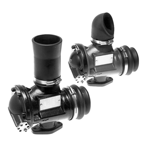
ITT Flygt 4901 Maintenance manual

892479/02
4901
Installation, care and maintenance GB
Betriebsanleitung D
Installation et entretien F
Instalación, servicio y mantenimiento E
Installazione e manutenzione I
Instalação, cuidados e manutenção P
Installatie en onderhoud NL
Installation och skötsel S
Installasjon, bruk og vedlikehold N
Installation, drift og vedligeholdelse DK
Asennus ja hoito FIN
EÔÊÁÔÁÓÔÁÓÇ, ÖÑ ÉÄÁ ÊÁÉ ÓÕÍÔÇÑÇÓÇ GR
RUS
Telepítés, üzemeltetés, karbantartás HUN

3
G
B
ITT Flygt guarantees that a spare part stock will be
kept for 15 years after the manufacture of this product
has been discontinued.
In accordance with our policy to constantly improve our
products, the specifications contained herein are sub-
ject to continuous change.
The manufacturer reserves the right to alter perform-
ance, specification or design without notice.
PRODUCT DESCRIPTION
General
The flush valve is primarily designed to flush and
cleanse a pump sump of sewage water and sludge
by mixing the sewage water automatically before
discharge. At the beginning of each pumping period the
valve is open and water from the pump is forced
through the valve into the sump as a jet flushing
stream. The water in the sump is subjected to a violent
motion and the sludge is stirred into suspension.
The flush valve is mounted on the pump housing and
its design is based on the ejector principle with a ball
as closing device. The operation is automatic and
induced by the pump flow and pressure, thus elim-
inating the need for electrical components and
cabling.
Applications
Sewage pumping stations equipped with Flygt pumps.
For installation on 3085–3300, on standard and
explosion proof pumps in a CP/DP installation
arrangement.
The pump housing must be pre-drilled and equipped
with a cast flat for the flush valve connection.
Performance
One flush valve 4901 should be sufficient to handle the
flushing of a pump station with a maximum diameter of
2.1 metres.
Liquid temperature
Max. 40°C.
For minimum temperature, refer to the freezing point of
the oil used in the valve oil casing.
Flushing time
The recommended flushing period for the 4901 is 20
sec. (Can be adjusted by the regulating valve.) The
flush valve is open when the pump starts and closes
after a chosen mixing period. The pump continues
pumping until the shut-off level is reached. The flush
valve opens again at the shut-off level.
Complete unit, flush valve, standard version
(556 51 01)
Black painted valve body.
Closing device
Cast iron ball.
Complete unit, flush valve, special version
(556 51 02)
Blue painted valve body.
Closing device
Polyurethane ball. (For low head applications with 3085
and 3102.)
Weight
Flush Valve (standard version) 8.0 kg
Flush Valve (special version) 7.4 kg
Limitations
As the operation of the flush valve depends on the
pressure and flow performance of the pump, operation
can be predicted by calculation* in borderline cases.
The lower limits at which the limitations should be
calculated are indicated in the table on the following
page.

4
Minimum permitted geodetic*** pump head without calculation.
PUMP VERSION CP 3085, CP/DP 3085, CP/DP 3127, 3140,
3102 HT 3102 LT**, MT 3152, 3170, 3201,
3300 LT/MT/HT
4901 STANDARD VERSION 556 51 01(Black painted valve body)
Type of outlet (Includes outlet bend 586 68 00)
Outlet bend 4.0 metres 4.5 metres 4.0 metres
586 68 00
Short outlet 4.0 metres 3.5 metres 3.0 metres
Outlet pipe 4.0 metres 3.0 metres 2.5 metres
558 08 00
Maximum allowable pump head (For Special version only)
The maximum allowable
geodetic pump head
is
3.5 metres.
The maximum allowable
pump operating head (duty
head)
is 5.0 metres. (Closed flush valve.)
* If the approved head is lower than indicated in the ta-
ble, contact your nearest ITT Flygt representative for a
calculation of the limitations.
** CP/DP 3085 performance curves with a shut-off
head of less than 7.0 metres should use the Special
Version.
*** Difference in height between the water level in the
sump and the highest point of the discharge pipe.
4901 SPECIAL VERSION 556 51 02 (Blue painted valve body) For CP/DP 3085/3102 only.
Type of outlet (Includes outlet bend 586 68 00 and outlet pipe 558 08 00)
Outlet bend
586 68 00 – 3.4 metres –
Short outlet – 2.7 metres –
Outlet pipe
558 08 00 – 2.3 metres –
MATERIAL
Description Material Flygt DIN BS ASTM
number
Major Cast iron 0314. 1691 1452 A48-83
castings 0125.00 GG-25 Grade No35B
260
Ball Cast iron 0314. 1691 1452 A48-83
(Standard 0125.00 GG-25 Grade No35B
version) 260
Ball Poly- 0556.
(Special urethane 9570.50
version)
Ball seat Stainless 0344. W.no AISI
steel 2324.02 1.4460 329
Regulating Brass 0456. CuZn CZ121 C36000
valve 5170.04 39Pb3
O-rings, inner Nitrile 0516.
membrane,out-
Rubber 2637.04
let pipe and 70°
outlet bend
Description Material Flygt DIN BS ASTM
number
Outer Nitrile
membrane rubber
and gasket 40°
Screws, Stainless 0344. W.no 316 AISI
studs, steel 2343.02 1.4436 S33 316
and nuts
Oil Rapeseed 901762
oil (0.25 l)
Oil Mineral oil
(Alternative) ISO VG 32
(0.25 l)
Surface Coating 902933 (black)
treatment Two 902936 (blue)
component.

5
G
B
219
319
261
128
153
291
Oil
Outer
membrane
Hose clamp
Valve body
Outlet bendRing
Valve body bottom
Soc et head screw
Inner membraneBallO-ring
Soc et head
screw
Regulating
valve
Hose clamp
Nut
Gas et
Stud
DESIGN
Lock nut

6
INSTALLATION
Safety precautions
See the “Care and Maintenance” for the appropriate
pump.
Mounting the flush valve on the
pump
The pump housings are pre-drilled and must be
equipped with a cast flat for the flush valve connection.
The drilling pattern is shown in Figure B. For further in-
formation, contact your nearest Flygt representative.
Setting flushing time
The 4901 flush valve is designed to support the three
possible executions;
1) with outlet bend
2) with outlet pipe
3) execution
without
outlet bend and
without
outlet
pipe is called “short outlet”.
The flushing time is determined by the regulating valve.
The delivery setting is “2”.
Recommended
approximative
first setting of the
regulating valve:
Execution Geodetic Pump Head (m).
< 4 4–10 > 10
Outlet bend
586 68 00 1 2 3
Short outlet 2 3 3–4
Outlet pipe
558 08 00 2 3 4
The recommended flushing period is 20 seconds.
Note. The flushing time for the special version may
vary more than for the standard version.
“Setting 2”
For a
shorter
flushing period, turn the regulating valve
to a
lower
setting.
Lock the regulating valve with the locking screw.
Note:
The flushing period is also affected by the oil viscosity
(the temperature of the water or of the air) and of the
underpressure in the valve body. The outlet pipe gives
the best underpressure and the outlet bend gives the
poorest underpressure. Therefore – be aware of the
limits!
Note. If the flush valve 4901 is used with the APF, a
maximum flushing period of 45 seconds should not
be exceeded.
Adjusting the regulating valve
Loosen the locking screw.
For a
longer
flushing period, turn the regulating valve
to a
higher
setting.
23
18
84
42 42
M 10
ø 46
Figure B

7
G
B
FUNCTION
Before start
The ball rests on the inner membrane. The oil is in the
oil chamber, the outer membrane is up and the inner is
down.
When the pump starts:
The valve is open when the pump starts. The flow from
the pump is led through the valve and the pump sump
is being flushed. An underpressure induced by the flow
occurs in the valve body. This underpressure begins in-
verting the outer and inner membranes and lifts the
ball. See figure 1.
When the valve is closed, the underpressure is instan-
taneously changed to overpressure, which forces the
membranes and the oil back to their initial positions.
See figure 3.
After approximately 20 seconds, the oil flows from the
oil casing to the space between the inner membrane
and valve body bottom via the regulating valve, forcing
the inner membrane to invert and thus pushing the ball
into the jetstream. The ball then obstructs the flow
through the valve and the pump begins pumping the liq-
uid out of the sump. See figure 2.
Figure 2.
Figure 3.
Figure 1.
Before first start:
During the running-in period there is some risk that
the valve will become clogged with solid particles
and sludge stirred up from the sediment on the
bottom. In order to prevent this, it is recommended
that the sump should be emptied and cleaned be-
fore the flush valve is put to use.

8
Oil
The flush valve 4901 is delivered with a rapeseed oil
which is “environmentally friendly”. The freezing point
of this oil is –30°C. An alternative to this oil is to use a
mineral oil in accordance with ISO VG 32.
Note
An oil with a higher viscosity gives a longer flushing pe-
riod and an oil with a lower viscosity gives a shorter
flushing period compared with the oil supplied.
The most frequent problem is that the inlet to the flush
valve is clogged by a hard particle, too large for the
valve throughlet.
Note
The maximum recommended flushing time is 50
seconds.
If the flush valve is working at a too low pressure, the
closing time will be extremely long regardless of the
regulating valve setting “1”. Finally the valve does not
close at all.
Please note the limits for each execution.
Providing the flush valve is operating within the limits,
but does not close within a reasonable time, perform
the following test:
– Replace the inner membrane.
– Grease the ball + the inner wall of the valve body*.
– Dismantle the outlet bend.
– Regulating valve setting “1”.
The flush valve should now close within max. 50
seconds if the reduced duty head is within the
limits.
Note
All other solutions, such as “own” outlet bends or
applications may destroy the required underpressure
and may lead to a non-closing flush valve.
* For the pumps 3085 and 3102, please note the
possibility of using the polyurethane ball instead of
the steel ball.
TROUBLESHOOTING
INSPECTION AND SERVICE
Inspection
Note. If the flush valve is taken out of the liquid for
more than four days, the ball and the inner wall of
the valve body should be greased.
The ball must be replaced if the diameter is less than
59 mm.
Major Overhaul
Under normal operating conditions, the flush valve
should be subjected to a major overhaul in a service
workshop every three years.

9
G
B
PARTS LIST
* Contact your nearest ITT Flygt representative for further information about impellers, pumps and pumphousings
approved for the flush valve.
Pos No Part No Denomination Quantity
556 51 01 Complete unit, flush valve, standard version 1
556 51 02 Complete unit, flush valve, special version 1*
1 556 52 00 Valve body, standard version 1
2 556 52 01 Valve body, special version 1*
3 84 54 19 Hose clamp 1
4 84 54 18 Hose clamp 1
5 586 68 00 Outlet bend 1
558 08 00 Outlet pipe 1*
6 562 43 00 Ring (ball set) 1
7 556 53 00 Valve body bottom 1
8 82 00 34 Socket head screw 6
9 556 57 02 Inner membrane 1
10 556 54 00 Ball, cast iron 1
11 556 54 01 Ball, polyurethane 1*
12 82 73 83 O-ring 2
13 556 56 00 Regulating valve 1
14 83 02 77 Socket head screw 1
15 80 95 07 Stud 2
16 502 53 00 Gasket 1
17 82 27 28 Lock nut 2
18 90 17 62 Oil 0.25 l
19 556 58 01 Outer membrane 1
18
19
3
56
7
8
910, 1112
14
13
4
1, 2
17
16
15

10
ITT Flygt garantiert, dass nach dem Auslaufen der Fer-
tigung dieses Produkts noch 15 Jahre lang Ersatzteile
dafür auf Lager gehalten werden.
Bedingt durch unsere Politik der fortlaufenden Weiter-
entwicklung unserer Produkte, unterliegen die in der
vorliegenden Broschüre enthaltenen Spezifikationen der
ständigen Änderung.
Als Hersteller behalten wir uns das Recht vor, die Lei-
stungs-, die Spezifikations- oder die Auslegungsdaten
ohne Vorankündigung zu ändern.
PRODUKTBESCHREIBUNG
Allgemeines
Das Spülventil dient in erster Linie dazu, Abwasser und
Schlamm aus einem Pumpensumpf herauszuspülen,
indem das Abwasser vor dem Abpumpen automatisch
gerührt wird. Zu Beginn jedes Pumpintervalls ist das
Ventil offen. Dabei wird aus der Pumpe kommendes
Wasser als Spülstrahl durch das Ventil unter Druck in
den Sumpf geleitet. Das Wasser im Sumpf wird in hefti-
ge Bewegung versetzt, und der Schlamm wird aufge-
rührt und dadurch in Suspension gebracht.
Das nach dem Ejektorprinzip arbeitende Ventil, das
eine Kugel als Verschlußelement besitzt, ist am Pum-
pengehäuse montiert. Das Ventil wird automatisch
durch die Pumpströmung und den Pumpdruck betätigt,
so dass keine Elektrokomponenten und Ver-
kabelungen erforderlich sind.
Anwendung
Mit ITT Flygt-Pumpen ausgestattete Abwasserpump-
stationen.
Für Installation an 3085–3300, an Standardpumpen
und explosionsgeschützten Pumpen in CP/DP-In-
stallationsanordnung.
Zum Anschluß des Spülventils muss das Pumpenge-
häuse vorgebohrt und mit einer angegossenen Fläche
ausgestattet sein.
Leistung
Ein Spülventil 4901 dürfte zum Spülen einer Pumpstati-
on bis 2,1 m Durchmesser ausreichen.
Medientemperatur
Maximal 40°C.
Mindesttemperatur siehe Gefrierpunkt des in der Ventil-
ölkammer verwendeten Öls.
Spülzeit
Für das Spülventil 4901 wird eine Spülzeit von 20 Se-
kunden empfohlen (mit Regulierventil einstellbar). Das
Spülventil ist offen, wenn die Pumpe anläuft, und
schließt sich nach der gewählten Rührdauer. Die Pumpe
fördert solange weiter, bis der Abschaltpegel erreicht
ist. Das Spülventil öffnet sich wieder beim Abschaltpe-
gel.
Spülventil, komplette Einheit, Standardversion
(556 51 01)
Schwarz lackiertes Ventilgehäuse.
Verschlußelement
Kugel aus Grauguss.
Spülventil, komplette Einheit, Spezialversion
(556 51 02)
Blau lackiertes Ventilgehäuse.
Verschlußelement
Kugel aus Polyuretan (für den begrenzten Einsatz mit
3085 und 3102).
Gewicht
Spülventil (Standardversion) 8,0 kg
Spülventil (Spezialversion) 7,4 kg
Begrenzungen
Da die Funktion des Spülventils vom Pumpdruck und
von der Pumpströmung abhängig ist, kann sie im
Grenzfall durch Berechnung* vorausgesagt werden. In
der nachstehenden Tabelle sind die unteren Grenzen für
die Begrenzungsberechnung angegeben.
11
D
PUMPEN- CP 3085, CP/DP 3085, CP/DP 3127, 3140,
VERSION 3102 HT 3102 LT**, MT 3152, 3170, 3201,
3300 LT/MT/HT
4901 STANDARDVERSION 556 51 01(schwarz lackiertes Ventilgehäuse)
Art des Auslasses (Einschliesslich Auslasskrümmer 586 68 00)
Auslasskrümmer 4,0 Meter 4,5 Meter 4,0 Meter
586 68 00
Kurzer Auslass 4,0 Meter 3,5 Meter 3,0 Meter
Auslassrohr 4,0 Meter 3,0 Meter 2,5 Meter
558 08 00
Zulässige minimale geodätische*** Förderhöhe ohne Berechnung
** Bei Leistungskurven für CP/DP 3085 mit einer Ab-
schalt-Förderhöhe von weniger als 7,0 m sollte die
Spezialversion verwendet werden.
*** Höhenunterschied zwischen dem Wasserpegel im
Sumpf und dem höchsten Punkt des Auslaufrohres.
Die zulässige maximale
geodätische Förderhöhe
be-
trägt 3,5 Meter.
Die zulässige maximale
Pumpenbetriebsförderhöhe
beträgt 5,0 Meter. (Bei geschlossenem Spülventil.)
* Wenn die genehmigte Förderhöhe unter dem in der
Tabelle angegebenen Wert liegt, lassen Sie sich bitte
von Ihrer nächsten ITT Flygt-Vertretung eine Berech-
nung der Einsatzbeschränkungen erstellen.
MATERIAL
Beschreibung Werkstoff Flygt- DIN BS ASTM
Nummer
Haupt- Grauguss 0314. 1691 1452 A48-83
gussteile 0125.00 GG-25 Sorte Nr 35B
260
Kugel Grauguss 0314. 1691 1452 A48-83
(Standard- 0125.00 GG-25 Sorte Nr 35B
version) 260
Kugel Poly- 0556.
(Spezial- uretan 9570.50
version)
Kugelsitz Rostfreier 0344. W-Nr. AISI
Stahl 2324.02 1.4460 329
Regulier- Messing 0456. CuZn CZ121 C36000
ventil 5170.04 39Pb3
O-Ringe, Innen- Nitril- 0516.
membran, Aus- kautschuk 2637.04 NBR NBR NBR
lassrohr und 70°
Auslasskrümmer
Beschreibung Werkstoff Flygt- DIN BS ASTM
Nummer
Außenmembran Nitril- NBR NBR NBR
und Dichtung kautschuk
40°
Schrauben, Rostfreier 0344. W-Nr. 316 AISI
Bolzen Stahl 2343.02 1.4436 S33 316
und Muttern
Öl Rapsöl 901762
(0,25 l)
Öl Mineralöl
(Alternative) ISO VG 32
(0,25 l)
Oberflächen- Zwei- 902933 (schwarz)
behandlung Kompo- 902936 (blau)
nenten-
Beschichtung
4901
SPEZIALVERSION 556 51 02 (blau lackiertes Ventilgehäuse) nur für CP/DP 3085/3102.
Art des Auslasses (Einschliesslich Auslasskrümmer 586 68 00 und Auslassrohr 558 08 00)
Auslasskrümmer
586 68 00 – 3,4 Meter –
Kurzer Auslass – 2,7 Meter –
Auslassrohr
558 08 00 – 2,3 Meter –
Zulässige maximale Förderhöhe (nur für Spezialversion)

12
18
19
3
56
7
8
910
,
1112
14
13
4
1, 2
17
BAUART
Innenmembran
O-Ring Kugel
Ring
(Kugelsitz)
Ventilgehäuse-Unterteil
Auslasskrümmer
Schraube
Regulierventil
Öl
Außen-
membran
Ventil-
gehäuse
Innensechs-
kantschraube
Packung
Stift-
schraube
Schlauch-
klemme
Sicherungsmutter Schlauch-
klemme

13
D
INSTALLATION
Sicherheitshinweise
Siehe „Anweisungen für Pflege und Wartung“ der jewei-
ligen Pumpe.
Montage des Spülventils
an der Pumpe
Das Pumpengehäuse muss einen angegossenen, ge-
bohrten Flansch haben, um das Spülventil anschließen
zu können. Das Bohrbild ist in Abbildung B dargestellt.
Näheres erfahren Sie bei Ihrer nächsten ITT Flygt-Ver-
tretung.
Einstellen der Spülzeit
Das Spülventil 4901 kann in drei verschiedenen Aus-
führungen eingesetzt werden:
1) mit Auslasskrümmer
2) mit Auslassrohr (muss extra bestellt werden)
3) Ausführung
ohne
Auslaßkrümmer und
ohne
Aus-
lassrohr, sog. „kurzer Auslass“.
Die Spülzeit wird durch das Regulierventil vorgegeben.
Werkseitig wird das Regulierventil auf „2“ eingestellt.
Empfohlene
Zirka
-Einstellung des Regulierventils:
Wenn Sie eine
kürzere
Spülzeit einstellen wollen: Re-
gulierventil auf einen
niedrigeren
Wert stellen.
Ziehen Sie die Sicherungsschraube wieder fest.
23
18
84
42 42
M 10
ø 46
Abb. B
Die Spülzeit sollte 20 Sekunden betragen.
Wichtig!
Die Spülzeit kann bei der Spezialversion stärker vari-
ieren als bei der Standardversion.
Ausführung Geodätische Förderhöhe (m).
< 4 4–10 > 10
Auslasskrümmer
586 68 00 1 2 3
Kurzer Auslass 2 3 3–4
Auslassrohr
558 08 00 2 3 4
Wichtig!
Wenn das Spülventil 4901 mit der APF verwendet wird,
sollte die Spülzeit nicht mehr als 45 Sekunden betra-
gen.
Einstellen des Regulierventils
Lösen Sie die Sicherungsschraube.
Wenn Sie eine
längere
Spülzeit einstellen wollen:
Regulierventil auf einen
höheren
Wert stellen.
Wichtig!
Die Spülzeit wird auch von der Viskosität des Öls
(Temperatur des Wassers oder der Luft) und vom Un-
terdruck im Ventilgehäuse beeinflußt. Das Auslassrohr
ergibt den besten Unterdruck, und der Auslasskrümmer
ergibt den schlechtesten Unterdruck.
Deshalb auf die Grenzen achten!
Vor dem Anlauf der Pumpe
Die Kugel ruht auf der Innenmembran. Das Öl befindet
sich in der Ölkammer, die Außenmembran ist nach
oben gewölbt, die Innenmembran nach unten.
„Wert 2“

14
FUNKTION
Beim Anlauf der Pumpe
Wenn die Pumpe anläuft, ist das Ventil geöffnet. Die
von der Pumpe kommende Strömung wird durch das
Ventil nach außen in den Sumpf geleitet, der auf diese
Weise gespült wird. Die Strömung durch das Ventil er-
zeugt einen Unterdruck im Ventilgehäuse. Aufgrund
dieses Unterdrucks wird die Außenmembran nach un-
ten und die Innenmembran nach oben bewegt und die
Kugel angehoben. Siehe Abbildung 1.
Nach zirka 20 Sekunden strömt Öl über das Regulier-
ventil von der Ölkammer in den Raum zwischen der In-
nenmembran und dem unteren Teil des Ventilgehäu-
ses. Dadurch wölbt sich die Innenmembran nach oben,
so dass die Kugel in den Strahlstrom gestossen wird.
Die Kugel verschließt dann den Durchgang durch das
Abbildung 1.
Ventil, und die Pumpe beginnt, die Flüssigkeit aus dem
Sumpf zu pumpen. Siehe Abbildung 2.
Nach dem Schließen des Ventils ändert sich der Unter-
druck schlagartig zu einem Überdruck, durch den die
Membranen und das Öl wieder in die Ausgangslage ge-
bracht werden. Siehe Abbildung 3.
Öl
Abbildung 2.
Vor der ersten Inbetriebnahme:
Während der Einlaufphase besteht Gefahr, dass
festes Material und Schlamm aus der Bodenabla-
gerung aufgerührt werden und das Ventil zusetzen.
Um dies zu vermeiden, wird empfohlen, den
Sumpf vor der Inbetriebnahme des Spülventils zu
leeren und zu säubern.
Das Spülventil 4901 wird mit umweltfreundlichem Raps-
öl geliefert. Der Gefrierpunkt dieses Öls liegt bei –30°C.
Statt diesem Öl kann auch ein Mineralöl gemäss ISO
VG 32 verwendet werden.
Abbildung 3.

15
D
INSPEKTION UND SERVICE
Wichtig
Ist die Viskosität des verwendeten Öls höher als die
des mitgelieferten Öls, verlängert sich die Spülzeit, ist
sie niedriger, verkürzt sich die Spülzeit.
Inspektion
Wichtig! Wenn das Spülventil länger als vier Tage
nicht in das Fördermedium eingetaucht ist, sollte die
Kugel und die Innenwand des Ventilgehäuses ein-
gefettet werden.
Die Kugel muss ausgetauscht werden, wenn ihr Durch-
messer kleiner als 59 mm ist.
Generalüberholung
Bei normalen Betriebsverhältnissen sollte das Spülven-
til alle drei Jahre in einer Kundendienstwerkstatt einer
Generalüberholung unterzogen werden.
Das häufigste Problem ist die Verstopfung des Spül-
ventileinlasses durch harte Partikel, die grösser als die
Ventildurchgangsöffnung sind.
Wichtig!
Die empfohlene maximale Spülzeit beträgt 50
Sekunden.
Wenn das Spülventil bei zu niedrigem Druck arbeitet,
ist die Schließzeit auch bei Einstellung des Regulier-
ventils auf „1“ außergewöhnlich lang. Im Extremfall
schließt das Ventil überhaupt nicht mehr.
Bitte beachten Sie die Grenzen für jede Ausführung.
Wenn das Spülventil innerhalb der Grenzen arbeitet,
sich jedoch nicht innerhalb einer vertretbaren Zeit
schließt, ist folgender Test durchzuführen:
– Innenmembran austauschen.
– Kugel und Innenwand des Ventilgehäuses* einfetten.
– Auslasskrümmer entfernen.
– Regulierventil auf „1“ einstellen.
Das Spülventil sollte sich jetzt innerhalb von maxi-
mal 50 Sekunden schließen, wenn die verringerte
Pumpenbetriebsförderhöhe innerhalb der Grenzen
liegt.
Wichtig!
Alle anderen Lösungen, wie beispielsweise „eigene“
Auslassskrümmer oder Anwendungen, können zur Zer-
störung des erforderlichen Unterdrucks und zum Nicht-
schließen des Spülventils führen.
* Bitte beachten Sie, dass bei den Pumpen 3085 und
3102 die Möglichkeit besteht, anstelle der Stahlkugel
eine Polyurethankugel zu verwenden.
FEHLERSUCHE

16
TEILELISTE
* Nähere Informationen darüber, welche Laufräder, Pumpen und Pumpengehäuse für das Spülventil genehmigt
sind, erhalten Sie bei Ihrer nächsten ITT Flygt-Vertretung.
Laufende Nummer Teilenummer Bezeichnung Menge
556 51 01 Spülventil, komplette Einheit, Standardversion 1
556 51 02 Spülventil, komplette Einheit, Spezialversion 1*
1 556 52 00 Ventilgehäuse, Standardversion 1
2 556 52 01 Ventilgehäuse, Spezialversion 1*
3 84 54 19 Schlauchklemme 1
4 84 54 18 Schlauchklemme 1
5 586 68 00 Auslasskrümmer 1
558 08 00 Auslassrohr 1*
6 562 43 00 Ring (Kugelsitz) 1
7 556 53 00 Ventilgehäuse-Unterteil 1
8 82 00 34 Innensechskantschraube 6
9 556 57 02 Innenmembran 1
10 556 54 00 Kugel, Grauguss 1
11 556 54 01 Kugel, Polyuretan 1*
12 82 73 83 O-Ring 2
13 556 56 00 Regulierventil 1
14 83 02 77 Innensechskantschraube 1
15 80 95 07 Stiftschraube 2
16 502 53 00 Packung 1
17 82 27 28 Sicherungsmutter 2
18 90 17 62 Öl 0,25 l
19 556 58 01 Außenmembran 1
18
19
3
56
7
8
910, 1112
14
13
4
1, 2
1
7

17
F
Température du liquide
Max. 40°C.
En ce qui concerne la température mini, elle est fonc-
tion du point de congélation de l’huile contenue dans la
chambre de la vanne.
Temps de brassage
La temps de brassage recommandé pour la vanne 4901
est 20 secondes. (Ce temps est réglable avec le clapet
de régulation.) La vanne de brassage est ouverte au
démarrage de la pompe et se referme après le temps
de brassage choisi. La pompe continue alors à pomper
jusqu’à ce que le niveau d’arrêt soit atteint et lorsque
c’est le cas, la vanne s’ouvre à nouveau.
Vanne de brassage, unité complete,
version standard (556 51 01)
Corps de vanne laqué noir.
Dispositif de fermeture
Boule en fonte.
Vanne de brassage, unité complete,
version spéciale (556 51 02)
Corps de vanne laqué bleu.
Dispositif de fermeture
Boule en polyuréthanne. (Pour utilisation limitée avec
pompes 3085 et 3102.)
Poids
Vanne de brassage (version standard) 8,0 kg
Vanne de brassage (version spéciale) 7,4 kg
Limites d’utilisation
Le bon fonctionnement de la vanne de brassage dépen-
dant de la pression et du débit de la pompe, il est pos-
sible de prévoir les performances par calcul* dans les
cas limites. Les limites inférieures en ce qui concerne
ce calcul ressortent du tableau sur la page suivante.
ITT Flygt garantit l’approvisionnement en pièces de re-
change pendant un délai de 15 ans après la fin de la
fabrication de ce produit.
Dans le cadre de notre politique d’amélioration cons-
tante de nos produits, nous nous reservons le droit de
modifier sans préavis les spécifications et caractéristi-
ques du produit ici décrit.
Généralités
La vanne de brassage a pour principale fonction de net-
toyer un puisard contenant des eaux d’égout et des
boues par dilution automatique du liquide avant éva-
cuation. Au début de chaque période de pompage, la
vanne s’ouvre et l’eau traversant la pompe est réinjec-
tée dans le puisard en un jet puissant. Cela crée un
violent effet de brassage du liquide contenu dans le
puisard, avec mise en suspension de la boue.
La vanne de brassage est montée sur la volute et son
principe de fonctionnement est celui d’un éjecteur,
avec dispositif de fermeture à boule. La commande de
la vanne est automatique et asservie au débit et à la
pression de la pompe. Cela élimine donc le besoin
de composants ou de câbles électriques.
Applications
Stations de relevage d’eaux d’égout équipées de pom-
pes Flygt.
Pour montage sur pompes 3085–3300 en version
standard ou antidéflagrante et formule d’installation
CP/DP.
La volute doit être prépercée et munie d’un méplat
venu de fonderie pour le raccordement de la vanne de
brassage.
Performances
Une vanne de brassage 4901 est suffisante pour le net-
toyage d’un puisard d’un diamètre maxi de 2,1 mètres.
DESCRIPTION

18
Hauteur de refoulement manométrique*** mini autorisée sans calcul
Description Matériau N° de réf. DIN BS ASTM
Flygt
Membrane Caoutchouc
extérieure nitrile
et joint 40°
Vis, Acier 0344. W.no 316 AISI
goujons inoxydable 2343.02 1.4436 S33 316
et écrous
Huile Huile de 901762
colza (0.25 l)
Huile Huile minérale
(option) ISO VG 32
(0.25 l)
Traitement Laque 902933 (noir)
de surface à deux 902936 (bleu)
composants
Description Matériau N° de réf. DIN BS ASTM
Flygt
Principales Fonte 0314. 1691 1452 A48-83
pièces 0125.00 GG-25 Grade No35B
coulées 260
Boule Fonte 0314. 1691 1452 A48-83
(Version 0125.00 GG-25 Grade No35B
standard) 260
Boule Poly- 0556.
(Version uréthanne 9570.50
spéciale)
Siège Acier 0344. W.no AISI
de boule inoxydable 2324.02 1.4460 329
Clapet Laiton 0456. CuZn CZ121 C36000
de régulation 5170.04 39Pb3
Joints toriques, Caoutchouc 0516.
membrane nitrile 2637.04
intérieure, 70°
diffuseur
VERSION CP 3085, CP/DP 3085, CP/DP 3127, 3140,
DE POMPE 3102 HT 3102 LT**, MT 3152, 3170, 3201,
3300 LT/MT/HT
4901 VERSION STANDARD 556 51 01 (Corps de vanne laqué noir)
Type de diffuseur (Y compris coude diffuseur 586 68 00)
Coude diffuseur 4,0 mètres 4,5 mètres 4,0 mètres
586 68 00
Sans diffuseur 4,0 mètres 3,5 mètres 3,0 mètres
Diffuseur droit 4,0 mètres 3,0 mètres 2,5 mètres
558 08 00
4901 VERSION SPÉCIALE 556 51 02 (Corps de vanne laqué bleu). Pour versions CP/DP
Type de diffuseur
3085/3102 uniquement (y compris coude diffuseur 586 68 00 et diffuseur droit 558 08 00)
Coude diffuseur
586 68 00 – 3,4 mètres –
Sans diffuseur – 2,7 mètres –
Diffuseur droit
558 08 00 – 2,3 mètres –
Hauteur de refoulement (Version spéciale uniquement)
La hauteur de refoulement manométrique maxi auto-
risée est de 3,5 mètres.
La hauteur de refoulement effective maxi autorisée
est de 5,0 mètres. (Vanne de brassage fermée.)
* Si la hauteur de refoulement autorisée est inférieure à
celle indiquée sur le tableau, veuillez contacter l’agen-
ce ITT Flygt pour calculer les limites d’utilisation.
** Les courbes de performances applicables aux ver-
sions CP/DP 3085 compte tenu d’un niveau d’arrêt de
moins de 7,0 mètres doivent faire intervenir la version
spéciale.
*** Différence de hauteur entre le niveau de l’eau dans
le puisard et le point le plus élevé de la canalisation de
refoulement.
MATERIAL

19
F
219
319
261
128
153
291
DÉSIGNATION
Collier
de serrage
Collier
de serrage
Huile
Corps
de vanne
Vis à six pans creux
Clapet
de régulation Fonds de corps
de vanne
Membrane intérieure
Boule
Joint torique
Bague
(siège
de boule)
Vis à six pans creux
Goujon
Joint
Ecrou de blocage
Membrane
extérieure
Coude
diffuseur

20
INSTALLATION
Consignes de sécurité
Voir la notice « Installationet entretien » de la pompe
concernée.
Montage de la vanne de brassage
sur la pompe
La volute de la pompe est prépercée et doit être munie
d’un méplat venu de fonderie pour le raccordement de
la vanne de brassage. Gabarit de perçage : voir fig. B.
Pour toute information complémentaire, veuillez con-
tacter l’agence Flygt.
Réglage du temps de brassage
La vanne de brassage 4901 est construite pour trois
possibilités de sortie pour l’eau :
1) avec coude diffuseur,
2) avec diffuseur droit,
3) sans diffuseur. Le temps de brassage est détermi-
né par le clapet de régulation.
A la livraison, le réglage est effectué sur « 2 ».
Temps de réglage initial
approximatif
recommandé :
Version Hauteur de refoulement
manométrique (m)
< 4 4–10 > 10
Coude diffuseur
586 68 00 1 2 3
Sans diffuseur 2 3 3–4
Diffuseur droit
558 08 00 2 3 4
Le temps de brassage recommandé est 20 secondes.
Nota
Le temps de brassage peut varier dans une plus grande
mesure pour la version spéciale que pour la version
standard.
Nota
Lorsque la vanne de brassage 4901 est utilisée avec le
système de régulation de niveau APF, le temps de
brassage ne doit pas excéder 45 secondes.
Réglage du clapet de régulation
Desserrez la vis de blocage.
Pour
augmenter
le temps de brassage, réglez le clapet
de régulation sur un chiffre plus
élevé.
« Position 2 »
Pour
diminuer
le temps de brassage, réglez le clapet
de régulation sur un chiffre
moins élevé.
Verrouillez le clapet de régulation en resserrant la vis
de blocage.
Nota
Le temps de brassage est également affecté par la vis-
cosité de l’huile (variable en fonction de la température
de l’eau ou de l’air) et la dépression régnant dans le
corps de vanne. La dépression est la plus forte avec
diffuseur droit et la plus faible avec coude diffuseur. Il
convient donc de tenir compte des limites d’utilisa-
tion!
23
18
84
42 42
M 10
ø 46
Fig. B

21
F
FONCTIONNEMENT
Avant mise en marche
La boule repose sur la membrane intérieure, l’huile
est dans la chambre, la membrane extérieure est en po-
sition haute et la membrane intérieure en position bas-
se.
Lorsque la pompe démarre
La vanne est ouverte au démarrage. Le débit en prove-
nance de la pompe est dirigé à travers celle-ci vers l’in-
térieur du puisard, qui est ainsi nettoyé. Ce débit crée
une dépression dans le corps de vanne, ce qui a pour
effet d’inverser les positions respectives des deux
membranes et de soulever la boule. Voir fig. 1 ci-
dessous.
Dès que la vanne est fermée, la dépression qui y
régnait se transforme en surpression, ce qui force les
membranes et l’huile à revenir dans leurs positions ini-
tiales. Voir fig. 3.
Après environ 20 secondes, l’huile contenue dans la
chambre pénètre, par le clapet de régulation, dans l’es-
pace compris entre la membrane intérieure et le fond
de corps de pompe, ce qui inverse à nouveau la posi-
tion de la membrane intérieure et chasse la boule dans
le flux d’eau, qu’elle obstrue du même fait, de sorte que
la pompe commence alors à évacuer le contenu du pui-
sard. Voir fig. 2.
Figure 2.
Figure 3.
Figure 1. Avant la première mise en marche :
Pendant la période de rodage, il existe un certain
risque d’engorgement de la vanne par des particu-
les solides ou de la boue détachées par le brassa-
ge des dépôts qui se sont formés au fond du pui-
sard. Pour éviter cela, il est recommandé de vider
et nettoyer le puisard avant de mettre la vanne de
brassage en service.
Other manuals for Flygt 4901
1
Table of contents
Languages:
Other ITT Control Unit manuals

ITT
ITT HYDROVAR Series User manual

ITT
ITT HydroAir 20-5202 User manual

ITT
ITT HYDROVAR HV 4.040 User guide

ITT
ITT Flygt 4901 Maintenance manual

ITT
ITT McDonnell & Miller 14-B Series Installation and operating instructions

ITT
ITT Engineered Valves CU27 User manual

ITT
ITT Skotch Trifecta T4305F Manual

ITT
ITT Skotch Trifecta T4600 Series Manual

ITT
ITT Engineered Valves EnviZion User manual

ITT
ITT Skotch Trifecta T4405F Manual