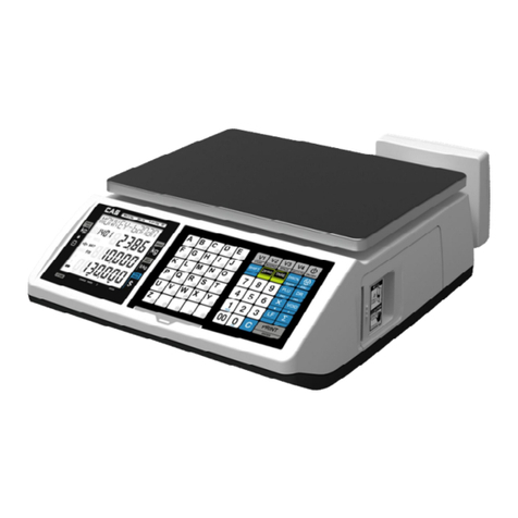
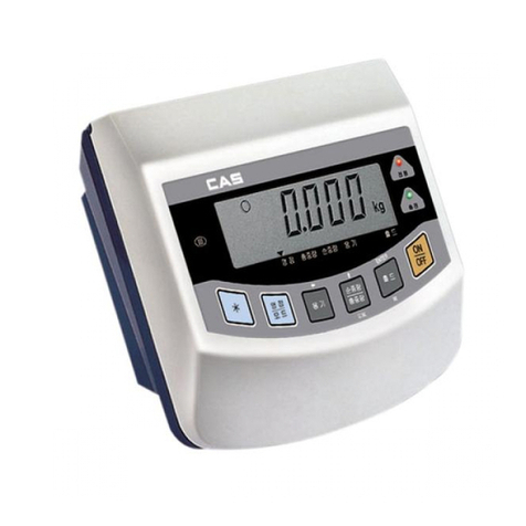
CAS NT-500 Series User manual

2

3
Table of Contents
1. Introduction......................................................................... 4
2. Features & Main function................................................ 6
3. Technical Specification...................................................... 7
4. Measure ofAppearance.................................................... 9
5. Front Panel........................................................................10
6. Rear Panel .........................................................................14
7. Installation & Connection..............................................15
8. Serial Communication (RS-232C) ...............................17
9. Test Mode...........................................................................20
10. Calibration Mode...........................................................24
11. Set Mode...........................................................................29
12. Weighing Mode ..............................................................46
13. Options.............................................................................53
14. Sealing Method...............................................................59
15. ErrorMessage & Troubleshooting.............................60

4
1. Introduction
Thank you for purchasing the CAS NT-500 Series weighing indicator. We have
designed this equipment with many advanced features, high quality construction,
and user-friendly menu driven programming. We are confident that you will find
the CAS NT-500 Series will meet all of your most demanding needs. CAS indicator
is shaped firmly and delicately designed to coincide with the special
requirements of several industrial fields and includes many functions and
various external interfaces. Also, it contains help display functions to be used
easily.
Before using NT-500 Series, It is recommended to read this manual carefully and
to apply the functionprecautions :
Precautions
Observe the following safety precautions :
Warning
When any damage or defect
occurs, contact your CAS
authorized dealer immediately
for proper repair.
Insert plug firmly to wall outlet to
prevent electric shock.
Scale must be grounded to
minimize electricity static. This
will minimize defect or electric
shock.
Do not pull the plug by its cord
when unplugging. Damaged
cord could cause electric shock
or fire.
To prevent from fire occurring,
Do not place or use the scale
near flammable or corrosive
gas.
To reduce electric shock or
incorrect reading, Do not spill
water on the scale or place it in
humid condition.

5
Avoid placing the scale near
heather or in direct sunlight.
Attention
For consistent and accurate
reading, maintain periodical
check by your CAS authorized
dealer.
Avoid sudden shock to the scale.
Internal mechanism could by
damaged.
Attach the rubber pad to the
bottom of the indicator.
Elimination is possible.
Place the scale on firm and
temperature consistent
environment.
Keep the scal away from othe electromagnetic generation devices.
This may interfere with accurate reading.
Our Dealers : CAS feels that each of its valued customers should get the best service
available. Whether it’s the initial installation of our product,
maintenance/repair work, or simply answering questions about our products,
CAS Corporation and all of its Authorized Dealers are highly trained to assist
you with any need regarding CAS products.

6
2. Features & Main Functions
1) Features
High quality, high accuracy
Appropriate for weight and measurement system
Easy operation and various options
Sub display of 12 digits(VFD) – Only NT-505A
RFI/EMI screened
Watchdog circuitry (System restoration)
Weight back up (Weight memory at sudden power failure)
2) Main Functions
Saving of date, time and calculated data at sudden power failure
Digital filter function
Adjustable A/D conversion speed (10~50 times/sec)
Various printer connection (serial, parallel)
Serial interface (RS-232C, RS-422/RS-485)
PC communication (PC command mode)
Set-point can save up to 50 batch operations
Users can set the max. weight and a division freely
External input 4 relay. (Refer to SET mode-F44)
External output 4 relay (zero, high, low, final) – Except NT-501A
Print date and time by built-in clock
Independent zero calibration
Display the high limit and the low limit at the VFD screen – Only NT-505A
Saving of measured weighing times
Self hardware test

7
3. Technical Specification
■Analog Part & A/D Conversion
Load Cell Excitation Voltage DC 9V, 8 x 350Ωload cells
Zero Adjustment Range 0.05mV 20mV∼
Input Sensitivity 1.2μV/D (H-44,OIML)
0.6μV/D (Non H-44,OIML)
System Linearity Within 0.01%of F.S.
A/D Internal Resolution 1 / 200,000
A/D External Resolution 5,000 dd (H-44,OIML)
10,000 dd (Non H-44, OIML)
A/D Conversion Speed Maximum 50 times/sec
■Digital Part
Span Calibration Full Digital Calibration : SPAC™
(Single automatic span calibration)
Display VFD (7 digit) : 6.0(W) x 13.0(H) mm
Sub Display (NT-505A) VFD (12 digit) : 3.3(W) x 8.0(H) mm
Division ×1, ×2, ×5
Display Below Zero Minus
Tare Subtraction Full capacity
“ST”(Stable) ▼LAMP Weight is stable
“HIGH” ▼LAMP Displays on/off status of high limit relay – Except NT-501A
“LOW” ▼LAMP Displays on/off status of low limit relay – Except NT-501A
“HOLD” ▼LAMP Hold function is activated
“NET” ▼LAMP ON(net weight), OFF(gross weight)
“TARE” ▼LAMP Tare is activated
“ZERO” ▼LAMP Current weight is “0” kg

8
■General Specification
Power AC 110V/220V, 50/60 Hz
Product Size 195(W) x 189(D) x 96 (H)
Temperature Range -10 ~ 40℃℃
Product Weight Approx. 2.5 kg
Fuse Capacity T250mA L250V
Power Consumption Approx. 10W
■Options
Option 1 RS-422/RS-485 serial interface
Option 2 BCD output
Option 3 Analog output(I-out : 0~24mA, V-out : 0~10V)

9
4. Measure of Appearance

10
5. Front Panel

11
1) Weight display - Display lamp (▼)
STABLE lamp : lights up when the weight is stable.
HIGH lamp : lights up when the high limit relay is activated.
LOW lamp : lights up when the low limit relay is activated.
HOLD lamp : lights up when you press HOLD key.
NET lamp : lights up when the display shows net weight.
TARE lamp : lights up when tare weight is stored.
ZERO lamp : lights up when current weight is 0 kg.
2) Sub display (NT-505A)
HIGH : It shows the high limit.
LOW : It shows the low limit.
3) Keyboard
NT-501A NT-502A, NT-505A
■Key
Used to remove small variations in the indicator’s zero. (user can set the zero range within
±2% or ±10% of the maximum capacity, see F10 at page 29).
Used to release tare.
Used to go to the “TEST” mode.

12
■Key
Toggles the display between gross weight weight. and net weight.
If tare weight is saved, tare plus item's weight is gross
weight and only item's weight is net weight. Used to go to the “SET” mode.
■Key (Weighed tare entry)
Used to weigh an item by using the container.
When this key is pressed, the scale stores current weight as the tare weight.
If you press key in unload condition, tare weight is released.
Used to enter the “CAL” mode.
■Key (Except NT-501A)
Used to see the high limit on the display, or change the high limit.
■Key (Except NT-501A)
Used to see the low limit on the display, or change the low limit.
■Key (Except NT-501A)
By pressing the key and then or key, high fall limit or low fall limit is shown on
the display
■Key
Manual Print Key. Designated printing form is printed.
Set print format in SET mode. (See F31 at page 32)
■or Key
Key Model Description
NT-501A Used to weigh live animals or an unstable items.
(Used as HOLD key)
NT-502A
NT-505A
F13 - 0 : Used as START key in packer mode.
F13 - 1 : Used to weigh live animals or an unstable item.

13
■or Key
Key Model Description
NT-501A
Manual tare entry. If the tare weight is previously known press
this key, and enter the tare weight by using the numeric keys,
and then press SET key register it.
(Used as MANUAL TARE key).
NT-502A
NT-505A
F13 - 0 : Used as STOP key in packer mode.
F13 - 1 : Manual tare entry.
If the tare weight is previously known press this key,
and enter the tare weight by using the numeric keys, and then
press SET key register it.
(Used as MANUAL TARE key).
■Key
Use (1) : Press “ID” key and type the ID code by pressing the numeric keys and then
the ID code is registered. Range of the ID code is 0 to 50.
Use (2) : Clear set-point by pressing this key for 2 seconds.
■Key
Use (1) : Used to clear erroneous entries.
Use (2) : Used to enter decimal point.
■Key
Used to save current condition and exit in Calibration, Test, Set mode.
■~ Key
Numeric Keys. Used to enter setting value, tare, ID code, etc.

1
4
6. Rear Panel
T250mA
■PRINTER : Parallel interface port
■INPUT : External input (Refer to SET mode-F44)
OUTPUT : External output (ZERO, HIGH, LOW, FINAL) - Except NT-501A
■SERIAL : RS-232C/422
■FUSE : 250mA 250V fuse.
■LOAD CELL : Port for connecting 4-wires, 6-wires load cell.
■OPTION : BCD output, Analog output (0-24mA or 0-10V)
■POWER : Power ON/OFF
PIN COLOR
1 (EXC+) RED
2 (SEN+) BROWN
3 (EXC-) WHITE
4 (SEN-) BLACK
5 (SIG+) GREEN
6 (SIG-) BLUE
7 (SHIELD) SHIELD
* Each lead cable that comes with NT-500
series contains color-coded wires as listed
above.

15
7. Installation & Connection
※This is L/C connector wire color enclosed with the product
1) Load cell connection
Connect load cell connector to load cell port which is in the backside of the indicator.
* Connecting method
Note 1. In case of 4 wires load cell, connect EX+ with SEN+, and connect EX- with SEN-.
Note 2. Wire color can be different depending on the load cell’s manufacturer or it’s model.
* Load cell output to Resolution
9V impression to loadcell
Max. load cell output Recommended resolution
2.4 mV 1/2,000 (Max.)
4.8 mV 1/4,000 (Max.)
6.0 mV 1/5,000 (Max.)

16
2) External input/output port connection
If you are away from indicator and you want to press key, please connect the indicator with
remote key via rear panel.
Multi Connector RELAY
1 ZERO RELAY
2 LOW RELAY
3 HIGH RELAY
4 FINAL RELAY
COM RELAY OUTPUT COM
RELAY OUTPUT
(Except NT-501A)
1 ZERO/TARE RELEASE/GROSS KEY
2 TARE/PRINT/NET KEY
3 GROSS/PRINT/HOLD/START KEY
4 GROSS/NET,GROSS/HOLD RELEASE
/STOP KEY
COM KEY INPUT COM
KEY INPUT
Refer to F44 at page
38.
3) AC Power
Adjusted to 220V 50/60Hz at factory.
(110V/220V jump wire is in the inner part of the indicator)
4) Internal load cell output switch
If the load cell output is too high, turn ON the Dip Switch 1
If the load cell output is too low or negative, turn ON the Dip Switch 2
(Load cell output switch is in the inner part of indicator)

1
7
8. Serial Communication (RS-232C)
1) RS232C connection
①How to Connect PC
Connect the serial port on the rear panel of the indicator to serial port of PC as follows.
RXD 3 ㅇ------------------------- ㅇ2 Transmit Data
TXD 2 ㅇ-------------------------- ㅇ3 Receive Data
GND 7 ㅇ-------------------------- ㅇ7 Signal Ground
┌─ ㅇ8 Carrier Detect
├─ ㅇ20 Data Terminal Ready
└─ ㅇ6 Data Set Ready
┌─ ㅇ4 Request to Send
└─ ㅇ5 Clear to Send
9pinport(Female) 25pinport(Male)
RS-232C port of NT-500 Series Serial port of computer
RXD 3 ㅇ------------------------- ㅇ3 Transmit Data
TXD 2 ㅇ-------------------------- ㅇ2 Receive Data
GND 7 ㅇ-------------------------- ㅇ5 Signal Ground
┌─ ㅇ1 Carrier Detect
├─ ㅇ4 Data Terminal Ready
└─ ㅇ6 Data Set Ready
┌─ ㅇ7 Request to Send
└─ ㅇ8 Clear to Send
9pinport(Female) 9pinport(Male)
RS-232C port of NT-500 Series Serial port of computer

1
8
How to Connect Sub Display (CD②-Series)
RXD 3 ㅇ------------------------- ㅇ2 Transmit Data
TXD 2 ㅇ-------------------------- ㅇ3 Receive Data
GND 7 ㅇ-------------------------- ㅇ7 Signal Ground
9pinport(Female) 9pinport(Male)
RS-232C port of NT-500 Series RS-232C port of sub-display
2) Data format
①Baud rate : 1200 bps - 19200 bps
Set Baud rate in SET mode. (See F20 at page 30)
②Data bit: 8, Stop bit: 1, Parity bit: None
Data bit: 7, Stop bit: 1, Parity bit: Even/odd
③Code : ASCII
④When data is sent to computer?
Set in SET mode(See F22 at page 31).
⑤Format
* 22 byte of CAS
. . .
DATA (8byte
)
CR LF
└─┘ └──┘ │└──────┐ │└──┘
US(Unstable) GS(GROSS weight) Device ID Lamp condition byte Empty Unit (kg/t)
ST(Stable) NT(NET weight)
OL(Overload)
- Device ID : Transmit 1 byte so that the receiver can receive data selectively which indicator
sent.(DeviceIDisselectedinF23.)
- Lamp condition byte
Bit 7 Bit 6 Bit 5 Bit 4 Bit 3 Bit 2 Bit 1 Bit 0
1 Stable 1 Hold Print Net Tare Zero
* 10 byte of CAS
DATA (8byte
)
CR LF
* 18 byte of AND
. .
DATA (8byte
)
CR LF
└─┘ └──┘ └──┘
US(Unstable) GS(GROSSweight) Unit(kg/t)
ST(Stable) NT(NET weight)
OL(Overload)

19
* Weight Data (8 byte)
a. 13.5kg : ' ', ' ', ' ', ' ', '1', '3', '.', '5'
b. 135kg : ' ', ' ', ' ', ' ', '1', '3', '5', ' '
c. -135kg : '-', ' ', ' ', ' ', '1', '3', '5', ' '
3) Command mode (F22-3 command mode)
Command Function Response
dd RW CR LF Reads the weight If dd RW CR LF is received, the indicator
will send the 22byte.
dd MZ CR LF Same as ZERO key
If dd MZ CR LF is received, the display
shows ZERO and dd MZ CR LF will be
sent to PC.
dd MT CR LF Same as TARE key
If dd MT CR LF is received, tare is activated
so ZERO, TARE lamp is on and dd MT CR
LF will be sent to PC.
dd HI 00000 CR LF Enter high limit value
(Except NT-501A)
Change the high limit value to 00000 (no
decimal point) and dd HI 00000 CR LF will
be sent to PC.
dd LO 00000 CR LF Enter low limit value
(Except NT-501A)
Change the lower limit value to 00000 (no
decimal point) and dd LO 00000 CR LF will
be sent to PC.
dd HE 00000 CR LF Enter high fall value
(Except NT-501A)
Change the high fall value to 00000 (no
decimal points) and dd HE 00000 CR LF
will be sent to PC.
dd LE 00000 CR LF Enter high fall value
(Except NT-501A)
Change the low fall value to 00000 (no
decimal point) and dd LE 00000 CR LF will
be sent to PC.
dd PN 00 CR LF Enter ID(00~50) Change the ID and dd PN 00 CR LF will be
sent to PC.
dd OP CR LF Use as START key
(Except NT-501A)
If dd OP CR LF is received, the indicator will
start in packer mode and dd OP CR LF will
be sent to PC.
(You have to set F40 to Packer mode)
dd EM CR LF Use as STOP key
(Except NT-501A)
If dd EM CR LF is received, the indicator
will stop in packer mode and dd EM CR LF
will be sent to PC.
(You have to set F40 to Packer mode)
dd : Device number☞
00000 : High limit value / low limit value/ high fall value/ high fall value☞
(If the setting value is “00345”, ASCII CODE is 0×30(hex), 0×30(hex), 0×33(hex),
0×34(hex), 0 ×35(hex))
* If the command is not accepted for any reason, I CR LF will be sent to PC.
* If an invalid character is received, ? CR LF will be sent to PC.

20
9. Test Mode
1) How to enter test mode
Turn on the power while pressing the key.
2) Available keys
~ key : used for changing preset value.
key : used for moving to initial test menu.
3) Test menu (TEST 1~9)
TEST 1 : Key test
TEST 2 : VF Display test
TEST 3 : Load cell test and A/D conversion test
TEST 4 : Serial interface test
TEST 5 : Printer test
TEST 6 : SRAM test
TEST 7 : External input/output test
TEST 8 : BCD output test
TEST 9 : Analog output test
TEST 1
FUNCTION : Key test
KEY VF
DISPLAY SUB
DISPLAY DESCRIPTION
: Menu selection
mode
Other keys: Perform test
1 1 tESt KEY Press any key to test then the display
shows its number and code.

21
< Key list >
KEY NO CODE KEY NO CODE KEY NO CODE
1 1
6 6
0 12
2 0
7 9
70 99
3 2
8 8
4 5
9 10
5 4
11 13
TEST 2
FUNCTION : VF Display test
KEY VF DISPLAY SUB
DISPLAY DESCRIPTION
:
Menu selection
mode
Other keys: Perform test
8.8.8.8.8.8.8.
▼▼▼▼▼▼▼
tESt2 VFd
888888888888
TEST 2 is performed.
TEST 3
FUNCTION : Load cell test and A/D conversion test
KEY VF DISPLAY SUB DISPLAY DESCRIPTION
: Menu selection
mode
5500 tESt3 AnALoG
The display shows digital
value of current weight.
This value means
converted digital value.
Note 1. Check whether the digital value is changing whenever you load or unload the weight
on the platter. If the digital value is fixed or zero is displayed, please check the
connection of loadcell.
This manual suits for next models
3
Table of contents
Other CAS Accessories manuals

CAS
CAS DH User manual

CAS
CAS SW II Series User manual

CAS
CAS CI-100A Installation and operating instructions

CAS
CAS CI-1500 User manual

CAS
CAS EXP-2000A User manual

CAS
CAS CI-600D Series User manual

CAS
CAS CI-2400BS User manual

CAS
CAS CI-502A User manual

CAS
CAS CI-2001AS User manual

CAS
CAS RW Series User manual