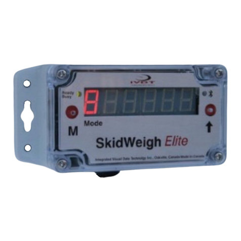
IVDT SkidWeigh ED2-SSL Series User manual

1
ED2-Series
SkidWeigh System
Automatic Check Weighing for Loading Shovels, Skid Steers, Loaders, Telehandlers and
Recycling Material Handling Vehicles
Ver.120706-22-SD4
ED2-L Series showing the load weight in t (tones)

2
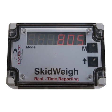
The ED2-SSL, ED2-CC and ED2-L Series SkidWeigh systems are an automatic heavy duty loader /forklift
checks weighing /overload warning system used to verify load weights on the move. This is not a “Legal for
Trade” scale, but an economical on-board check weighing system that will allow your loader operator to
increase vehicle utilization, increase productivity, provide operator safety and display the load weights
readout within +/-0.5% to +/-1% of the vehicle’s lifting capacity. The load weight readouts are available for
pounds, kilograms and tones.
Proper Operator Procedure for Weighing Loads
Dynamic Weighing Method
To obtain a load weight readout the lift truck operator is to lower the loaded bucket / forks to the ground,
wait until the indicator MODE shows the number
8
and then the load is being lifted without any
interruption until load weigh is shown on the indicator.
All load weighing must be performed at engine idle speed (or at designated engine RPM) and lift control
valve open fully.
As soon as the load has been lifted, the digital display will go blank for a moment and then the weight value
of the lifted load will be displayed. The load weight is automatically measured during an uninterrupted lift.
The current load weight will be shown on the display until the next time the load is being lowered.
Do not start to tilt the load in any other direction and keep the lifting cycle smooth and at the constant lifting
speed, engine idling and apply full lift.
Static Weighing Method
To obtain a load weight readout the lift truck operator is to lower the loaded bucket / forks to the ground,
wait until the indicator MODE shows the number
8
and then lift the load just above the ground. As soon
as the load has been lifted, the digital display will go blank for a moment and then the weight value of the
lifted load will be displayed. The lifted load weight will be shown on the display within few seconds. The
current load weight will be shown on the display until the next time the load is being lowered.
Do not attempt to slow down this operation. Do not start to tilt the load in any other direction and do not lift
the load to the different heights.
Note: The weighing / operational method must be determined during the normal calibration procedure.
Empty bucket on the ground
Load lifted just above the ground

3
Mounting Location for Digital Indicator
The compact design and light weight the ED2 Series digital indicator can easily be mounted within the
operator’s compartment. Select a suitable location and using the mounting bracket with the anti-vibration
mount install the digital indicator on the vehicle’s dashboard preferably on the right hand side. A bracket can
be bolted onto a lock striker plate, window frame or turret support.
Anti-vibration mount, ¼”-20 UNC (25 x 20 mm, vulcanized rubber, Duro5) supplied with every kit
Pressure Transducer Installation
1. The pressure transducer body itself has a male port ¼”-18 NPT. Standard pressure transducer
cable length is 6’ (1.5 meters).

4
2. The pressure transducer must be installed in the hydraulic line between the lift control valve
and the lift cylinder(s). If possible locate a hydraulic fitting that can be removed to allow drilling
and tapping. Failing this a hydraulic adaptor can be fitted. Connect appropriate fitting and hose to
allow pressure transducer to be mounted in a safe location. Connect the transducer to the hydraulic
line. Start the engine and bleed the air from the line, then tighten the transducer
Pressure Transducer Cable
1 Red, 2 White, 3 Black
Seven Wires Cable
Electrical connections
(For Vehicle Input Voltage’s from 12 to 55V DC)
RED Wire of pressure transducer cable to RED WIRE of the 7 wires cable from the indicator
BLACK Wire of pressure transducer cable to BLACK WIRE of the 7 seven wires cable from the
indicator
WHITE Wire
of pressure transducer cable to WHITE WIRE of the 7 wires cable from the indicator
ORANGE Wire
(+)
Connect to the ignition switch “ON” position
BROWN Wire
(-)
Connect to battery negative (Electric motor powered vehicles) or to the vehicle
chassis of combustion engine powered vehicles.
BLUE and GREEN Wires: Connection to the external overload warning, over/under load weight.
This is N.O. (normally open relay contacts, maximum 1A resistive load).

5
Digital Indicator Calibration / Setup Two Keys Description
Upper Right Key Labeled “M” (Calibration / MODE key)
Lower Right Key Labeled “⇑
⇑⇑
⇑” (0 – 9 numerical increments input key)
MODE Five Digits Load Weight Readout Display
8
Digit 5
Digit 4
Digit3
Digit 2
Digit 1
Note: Both keys, Mand ⇑
⇑⇑
⇑are used only during the system calibration/set up mode. They can be accessed
through two small holes on the polycarbonate cover. (Use a paper clip to activate the keys)
•The left most significant digit represents the MODE of operation
•The five other digits represent the load weight readout
Calibration / Setup Procedures Concept
The ED2 Series SkidWeigh systems calibration/setup procedures are very simple. There is no input of the
complicated codes as found on the majority of forklift / loader on-board weighing systems on the market;
but the simple procedure that utilize two buttons and few steps to complete the automatic calibration.
Automatic calibration of the empty forks/ bucket being lifted and than automatic calibration of the
known load weight being lifted is all what is required.
Note: At any point if you make a mistake, for whatever reason, turn the power to the system OFF / ON and
start all over. All final calibration and set-up values will be automatically stored after the calibration/setup
procedures are finished. If power to the ED2 Series is disconnected information will NOT BE LOST.
•The ED2 Series system has to be calibrated with a known load weight
•Use the customer’s floor scale or find a known load weight within the operating facility
•Keep that known load weight nearby to complete the calibration
•For best results, use at least 30% to 50 % known load weights of the particular lift truck’s lifting
capacity.

6
•Example: For 3000 pounds lifting capacity of the vehicle, use at least 1500 pounds or close to that
load weight to be used to calibrate the system.
•
Note: If you want the system to show load weight in pounds; use the known load weight in pounds
and enter that value accordingly. The same would apply if you want the weight display to show in
kilograms. Use a known load weight in kilograms and enter that value into the system accordingly.
Some customer prefers that load weight is displayed in tones. In this case you must order ED2-L
Series SkidWeigh.
Example: Display shows 1.670 t
Starting Point
There are two ways of taking a weight reading with the ED2 Series; either in DYNAMIC or in the STATIC
weighing method. In both cases the load weight is measured automatically, either by lifting the load just
above the ground or lifting the load without any interruption, at steady and smooth lifting speed until the load
weight value is displayed on the indicator. The DYNAMIC weighing method might be convenient to the
operator. STATIC weighing might provide you with better weight readout results. It is recommended to find
out the best weighing method for your application. Many external configuration on vehicle hydraulic lift
circuit such as safety blocking valves, unique mechanical linkages, double or single acting lift cylinder’s,
check valves, flow dividers, hydraulic accumulators, etc. will be the factor in determining the appropriate
weighing method.
Some telehandlers are equipped with a holding valve on lifting cylinder and there is no predisposition on
this valve to fit a pressure sensor. In addition the boom load of the telehandler the load might be is also
maintained by the tilting circuit through compensation cylinders and therefore the weight of the load is not
completely transmitted into the lifting cylinder.
The installation does not change and with simple two button ED2 automatic calibration procedure the
both weighing methods & calibration and testing can be done within few minutes.
Depending on your operational needs and the initial calibration results you will have to decide to use either
DYNAMIC or STATIC weighing method during the system calibration and the system usage.
Every time the power is turned on, the software version will be shown on the right hand side of the
display for a brief moment. Example of one of the software version is 9771. When bucket / forks are
lowered to the ground, the digital display will show number 8 in the Mode window.
MODE
Five Digits Load Weight Readout Display
8

7
STATIC Weighing Method & System Calibration
Calibration of the Empty Bucket / Forks
Lower the empty bucket or forks to the ground (No hydraulic pressure in the lifting circuit)
•To access the calibration function press the “M” key and hold it down for 5 seconds.
•After 5 seconds, the MODE display digit will show “0”. This means that the system is ready for
automatic zeroing of the scale.
MODE
Five Digits Load Weight Readout Display in %
0
•Lift the empty bucket (fully crowded) or forks or any other attachment just above the ground.
(Activate the lift control valve, as you would do during the normal lifting operation.
•
Wait a few seconds, the display will go blank and then it will show 0in the furthest right digit display
(Digit 1).
(If scale previously calibrated than could be 0 or any other number already in the system)
MODE
Five Digits Load Weight Readout Display in %
1
0
Automatic zeroing of lifted empty bucket / forks (or any other attachment) is done!

8
Calibration of Loaded Bucket / Forks
(Example: Known Load Weight is 1500)
•At this point, drive the vehicle into the skid with a known load weight. (If this is a typical pallet with
known weight, make sure that the forks are in the pallet and are lowered to the ground. In the
case of the bucket make sure that the loaded bucket fully crowded and lowered to the ground.
•Start entering a known load weight into the digital indicator. The first value of the known load
weight can be entered by pressing the “⇑
⇑⇑
⇑” key.
•The number will increment from 0 to 9 and will wrap around.
•To enter a second digit from the right, press the “M” key and the MODE digit will increment to 2.
•
Keep pressing “⇑
⇑⇑
⇑” to enter a second value of known load weight.
•Repeat this procedure until the MODE digit display is showing 5.
Note: In our example known load weight is 1500. Make sure that you enter 0in MODE 5, since the
known load weight has only 4 digits as in our example of 1500. This value of 1500 could represent
kilograms or pounds.
MODE
Five Digits Load Weight Readout Display
1
0
MODE
2
0
MODE
3
5
MODE
4
1
MODE
5
0
•Before going to MODE 6 please make sure that the “Known load weight” (in our example, 1500
pounds or kilograms) is ready to be lifted. The loaded forks must be on the ground (No hydraulic
pressure in the lifting hydraulic circuit).

9
•Press the “M” key to advance to MODE 6 and immediately lift the loaded bucket or forks just above
the ground.
•(Activate the lift control valve, as you would do during the normal lifting operation).
MODE
Five Digits Load Weight Readout Display
6
•The display will go blank. Wait a few seconds. (Do not move forks, do not tilt or activate side shift
lever)
•Within a 3-5 seconds the display will show the value of the calibrated “known load weight”, in our
case 1500. If you lower the load to the ground system will go automatically into operational mode.
•Number 8 will be shown in the MODE window. System is calibrated and ready to be used!
System Weigh Calibration Function is finished!

10
DYNAMIC Weighing Method & System Calibration
Calibration of the Empty Bucket / Forks
Lower the empty bucket or forks to the ground (No hydraulic pressure in the lifting circuit)
•To access the calibration function press the “M” key and hold it down for 5 seconds.
•After 5 seconds, the MODE display digit will show “0”. This means that the system is ready for
automatic zeroing of the scale.
MODE
Five Digits Load Weight Readout Display in %
0
•Lift the empty bucket (fully crowded) or forks or any other attachment at engine idle, a smooth
speed (Open lifting valve fully to raise the load), DO NOT stop the lift cycle until Mode number
changes from 8 to1.
•
Within a few seconds the display will go blank and then it will show 0in the furthest right digit
display (Digit 1).
(If scale previously calibrated than could be 0 or any other number already in the system)
MODE
Five Digits Load Weight Readout Display in %
1
0
Automatic zeroing of lifted empty bucket / forks or any other attachment is done!

11
Calibration of Loaded Bucket / Forks
(Example: Known Load Weight is 1500)
•At this point, drive the vehicle into the skid with a known load weight. (If this is a typical pallet with
known weight, make sure that the forks are in the pallet and are lowered to the ground. In the
case of the bucket make sure that the loaded bucket is fully crowded and lowered to the ground.
•Start entering a known load weight into the digital indicator. The first value of the known load
weight can be entered by pressing the “⇑
⇑⇑
⇑” key.
•The number will increment from 0 to 9 and will wrap around.
•To enter a second digit from the right, press the “M” key and the MODE digit will increment to 2.
•
Keep pressing “⇑
⇑⇑
⇑” to enter a second value of known load weight.
•Repeat this procedure until the MODE digit display is showing 5.
Note: In our example known load weight is 1500. Make sure that you enter 0in MODE 5, since the
known load weight has only 4 digits as in our example of 1500. This value of 1500 could represent
kilograms or pounds.
MODE
Five Digits Load Weight Readout Display
1
0
MODE
2
0
MODE
3
5
MODE
4
1
MODE
5
0
•Before going to MODE 6 please make sure that the “Known load weight” (in our example, 1500
pounds or kilograms) is ready to be lifted. The loaded bucket or forks must be on the ground (No
hydraulic pressure in the lifting hydraulic circuit).

12
•Press the “M” key to advance to MODE 6 and immediately start lifting the loaded bucket or forks at
engine idle at smooth speed (Open lifting valve fully to raise the load), DO NOT stop the lift cycle
until Mode number changes from 6to calibrated load weight entered into the system.
(With engine at the idle speed, activate lift control valve fully, do not stop until you get weight
readout).
MODE
Five Digits Load Weight Readout Display
6
•The display will go blank. Wait a few seconds.
•Within a 3-5 seconds the display will show the value of the calibrated “known load weight”, in our
case 1500. If you lower the load to the ground system will go automatically into operational mode.
•Number 8will be shown in the MODE window. System is calibrated and ready to be used!
System weigh calibration function is finished!
From this point on, the system weigh calibration/setup has been successfully done and all the calibrating
parameters are saved and will not be lost when the power to the system is turned off. The display will show
the load weight value until the forks are lowered to the ground. When the forks are lowered to the ground,
the display will automatically reset and the system will go into MODE 8 which is a starting point for all
weighing cycles.

13
If another weighing cycle is not to be initiated and the vehicle is in motion or the forks are lifted during
normal operation, the hydraulic pressure “spikes” will be introduced and some random readout value on the
digital display will be shown. The value displayed might be 0, 10, 20, 25, etc.
This readout value does not represent the load weight, but is only a readout value due to the vehicle motion
and the system automatic weight cycle.
Overload Warning Feature (Optional)
The ED2 Series or any other models with such features will allow the end user to enter any overload
warning value that is applicable for that particular operation. Once the pre-set “Overload Value” is entered
into the system, every time that pre-set overload value is reached, the indicator display will ”flash” and the
value of the overload load weight will be shown to the operator.
Overload warning buzzer is optional.
To stop the LED display ”flashing” (Overload warning), the operator must lower the load to the ground.
Overload Warning Input Value (MODE 7)
All ED2 Series SkidWeigh with such overload features require an additional step in the standard calibration
procedure. This Mode 7 will come up automatically on the ED2’s after the standard calibration procedure
is finished and loaded bucket or forks are lowered to the ground.
(As of example, we want to enter “Overload Warning Value” of 4000)
How to get to the MODE 7?
The ED2 SkidWeigh systems with “Overload Warning Input Feature” will have a MODE 7 as
a next step after system calibration procedure. As soon you have finished with the MODE 6
and the display is showing the current calibrated load weight (In our example it was 1500)
you must lower the loaded bucket or forks to the ground. As soon the loaded bucket or forks
are lowered to the ground the mode number will automatically advance to the MODE 7.
When in the MODE 7 you must enter the “Overload Warning Value” for that particular vehicle.
The MODE 7 digit will remain while entering the ‘Overload Warning Value”.

14
MODE Five Digits Load Weight Readout Display
7
0
•Using the same keys “M” and “⇑
⇑⇑
⇑”, enter the “Overload Weight Value”. In our example it’s 4000.
You will note that the MODE 7 digit remains throughout this operation. (Make sure that 5
th
digit is 0)
MODE Five Digits Load Weight Readout Display
7
0
MODE
7
0
MODE
7
0
MODE
7
4
MODE
7
0
On the last shift, (Utilizing “M” key, left shift) the MODE 7 digit will turn off. The “Overload Weight Value” will
be successfully stored in the memory.
MODE
Five Digits Load Weight Readout Display
7
0
4
0
0
0
The entered value of 4000 will be shown briefly on the digital display and the unit will return to the
normal operational MODE 8.
MODE
8
The System Calibration and the “Overload Warning Value”
Have Been Successfully Stored in the Memory

15
ED2 Series with Two Independent Weighing Channels
(Two position switch located on the top of the instrument housing)
The ED2-2X version of the SkidWeigh or any other models with such a feature has an additional weighing
channel that can be used to verify load weights on vehicles operating with other attachments (extension
forks, bucket, clamps or lifting container buckets, etc.) Some material handling operations require frequent
changes between the “normal forks” and other special attachments. This two channel Skidweigh is a
convenient and time saving way to continue check weighing regardless of the attachment type in usage on
the vehicle.
Calibration:
The system has a two-position switch located on top of the indicator housing.
Mode 8 (First Weighing Channel) and Mode 82 (Second Weighing Channel).
In Mode 8 perform the calibration procedure as outlined previously. When finished with calibration of first
weighing channel turn vehicle power OFF/ON, and than flip the switch to the Mode 82.
Once in the Mode 82 perform the same calibration procedure as done previously with first weighing
channel, only this time calibrate the system with another attachment.
“Example long extension forks, bucket, etc.”
Operator Usage Procedure:
The operating procedures are the same for both channels
Note: If the accumulative function or the onboard printer is utilized, you can switch between channels as
required. The system will automatically add the accumulative weighing loads for both weighing channels.

16
Accumulative Load Weight Function Without Onboard Printer:
Left Button:
Accumulative function for load weights
Every time the indicator shows the load weight and the left button is pressed, the load weight will be
added into a weighing counter and will show the current total weight of all load weights entered in the
counter. (A quick “blink” on the display indicates that the current load weight has been added into the
counter.)
To reset the current load weighing counter, press the right button. This will reset the current total and the
cycle will start all over.
Right Button
: Reset
Note: Weight loads can be added only while the indicator shows the current load weight. If the load weight
is lowered and Mode 8 is shown on the display, the last load weight will not be added even if the left
button is pressed.
The maximum number of load weights entered into the accumulative counter is 40. If 40 loads have been
reached, the display will show the current total weight of all 40 loads weight entered. This current total
weight will stay and “flash” on the instrument display for a moment. The current accumulative counter of all
40 loads weight will be reset automatically and you can start the new cycle again.

17
Accumulative Load Weight & Printouts With Onboard Printer:
Left Button:
Accumulative Function for load weights
Right Button
: Print/Reset
Every time the indicator display shows the load weight and the right button is pressed, the current load
weight ticket will be printed and the system load weight counter will be RESET.
Example of single load weight being printed:
IVDT Skidweigh
4380
Every time the indicator shows the load weight and the left button is pressed, the load weight will be added
into a load weighing counter. It will also show the current total weight of all load weights entered in the load
weight counter. (A quick “blink” on the display indicates that the current load weight has been added into the
counter)
At any point you can obtain a ticket for all entered load weights stored in the load weighing counter by
pressing the right button. The printout will show all individual load weights and total weight. As soon as
you lower the forks and the last load weight is no longer on the display, the system will be RESET.
Example of two load weights added in the weighing counter and being printed:
IVDT SkidWeigh
#01 = 01550
#02 = 01000
TOTAL = 2550
The maximum number of load weights entered into the accumulative load weigh counter is 40. If the
number of 40 loads has been reached, the display will show the current total weight of all 40-load weights
entered. This current total weight will stay and “flash” on the instrument display for a moment. The current
accumulative counter of all 40 load individual weights and total weight will be printed out. The system will
reset automatically and you can start the new cycle again.

18
Example of 40 load weights added in the weighing counter and being printed:
IVDT SkidWeigh
#01 = 01550
#02 = 01000
“ “
#40 = 01265
TOTAL = 42550

19
On-board Printer Mounting Bracket
Note:
-The onboard printer, (NCI Dot Matrix MiniPrinter Series or CEN-DM Thermal Printer) is 12V
-Printer can be powered only through IVDT Inc. wiring harness since power from the vehicle
can be anywhere from 12 to 55V DC. Only through original wiring harness the printer will
get 12V DC from the ED2-SkidWeigh Series Digital Indicator, regardless of the vehicle
operating voltage.
-Use the IVDT Inc. printer mounting bracket.
-Use two Anti-vibration mounts when printer is used
-Consult printer User’s Manual for installing the paper, printer ribbon, etc.

20
ED2 Series SkidWeigh MODE Description
MODE 8 Represents Standard Operational “Weighing Cycle Mode”
MODE 0 to 6 Represents standard calibration mode
MODE 7 Represents Optional “Overload Warning Input Value Set-up”
MODE
Description
Action
Remarks
8
Standard “Weighing Cycle Mode”
Lower the forks to the
ground
MODE 8
must be
shown to initiate
the weighing cycle
0
Automatic zeroing of empty forks
Forks must be lowered
to the ground. Lift the
empty forks
Lift empty forks
just above the
ground
1
Enter first value of known load weight
0 – 9 numerical
increments, use ⇑key
Press the “M” key
to advance to the
next MODE
2
Enter second value of known load weight
0 – 9 numerical
increments, use ⇑key
Press the “M” key
to advance to the
next MODE
3
Enter third value of known load weight
0 – 9 numerical
increments, use ⇑key
Press the “M” key
to advance to the
next MODE
4
Enter forth value of known load weight
0 – 9 numerical
increments, use ⇑key
Press the “M” key
to advance to the
next MODE
5
Enter fifth value of known load weight
0 – 9 numerical
increments, use ⇑key
Press the “M” key
to advance to the
next MODE
6
Automatic calibration mode with known
load weight on the forks
The forks must be on
the ground level. Lift
the forks with the
known load weight
After a few
seconds, the
display will show
the known load
weight value
7
Overload Warning Input Value Set-up
Enter Overload
Warning Value as per
instructions described
above.
Applies only for
systems with the
overload warning
option
This manual suits for next models
2
Table of contents
Other IVDT Accessories manuals

IVDT
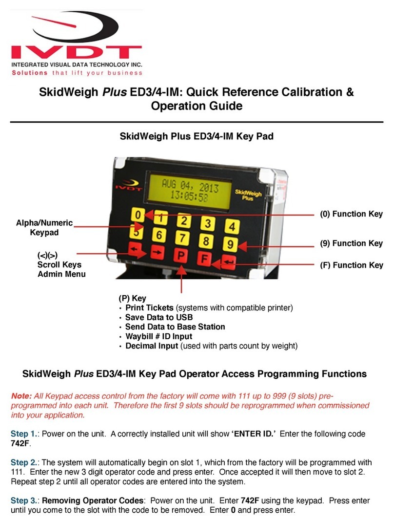
IVDT SkidWeigh ED2-AT Series Use and care manual

IVDT
IVDT SkidWeigh ED2E-EP Series Use and care manual

IVDT
IVDT SkidWeigh ED2 Series Setup guide

IVDT
IVDT SkidWeigh Plus ED3-IM User manual

IVDT
IVDT SkidWeigh ED2-EP Use and care manual

IVDT
IVDT SkidWeigh ED2-EPT Series User manual

IVDT
IVDT SkidWeigh ED7 Series Use and care manual