IVDT SkidWeigh ED2-AT Series Use and care manual

Installation & Calibration
ED2-AT Series SkidWeigh System
Lift Truck On-board Check Weighing With Accumulative Load Weight Total
ED2-AT Series SkidWeigh V.1.1
Integrated Visual Data Technology Inc. 3439 Whilabout Terrace, Oakville, Ontario, Canada L6L 0A7

General Installation Guide
This ED2-AT Series SkidWeigh system installation & calibration guide describes how to install, calibrate, test and use
your on-board check weighing unit. Following the instructions in this guide will enable you to get your system operating
quickly and easily. In the event that you require additional assistance, please contact customer support via e-mail at
Integrated Visual Data Technology Inc.
3439 Whilabout Terrace, Oakville, ON, Canada, L6L 0A7
Phone: 905-469-0985, Fax: 905-825-9494
Safety
Always disconnect the vehicle battery while installing SkidWeigh system or any other electronic product.
Make sure sure that unit, pressure transducer and any other associated cables are securely mounted and do not impede
any of the vehicle’s controls. Use care when routing the components cables. Route the cables where they will be
protected. Use commonly accepted install practices for after market industrial vehicle electronic devices.
The installation of the SkidWeigh systems should only be performed by an acknowledged lift truck dealer technician or
end user electro and hydraulic technical installer.
Here are two acceptable methods of making a wire connections:
* Soldering your connections (recommended)
* Crimp connectors ( with the use of the proper crimping tool)
Regardless of the method you choose, ensure that the connection is mechanically sound and properly insulated. Use
high quality electrical tape and shrink tubing where necessary.
This product is connected directly to the vehicle’s ignition switch, 12 to 55 V DC. There is no on-off switch on the unit.
Electro-Magnetic Compatibility
CE conformity to EC directive 89/336 (EMC) by application of harmonized standards: Interference stability EN 61000-6-2
and EN 61326-1 interference emit EN 61000-6-3, EN 61326-1 for the pressure transducer.
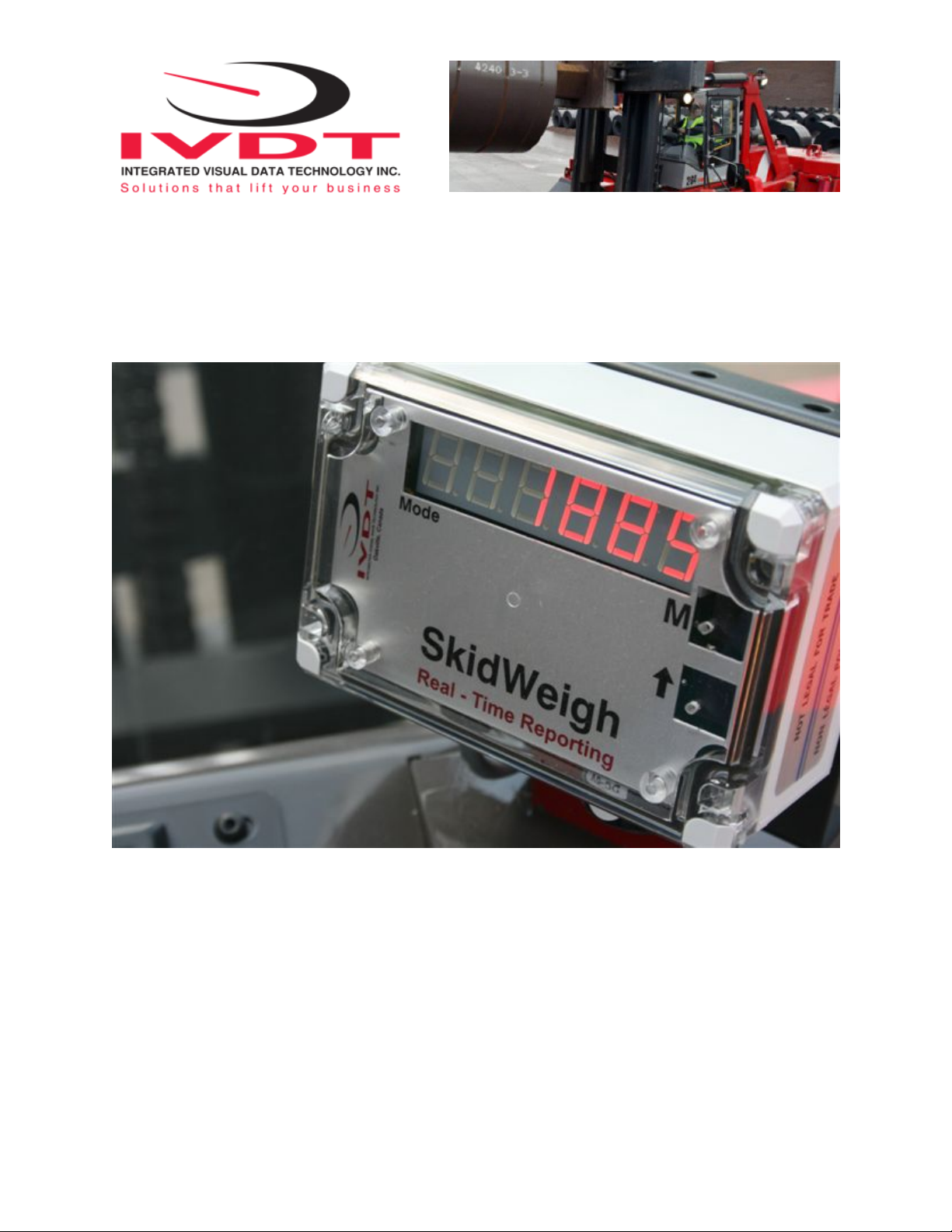
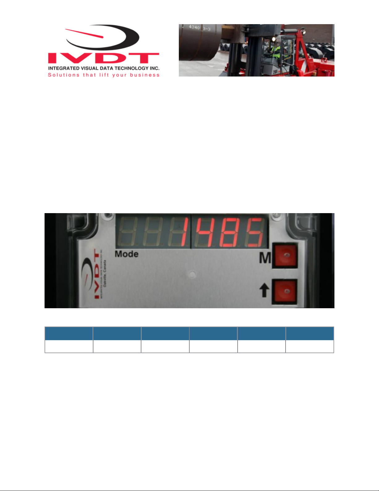
ED2 SkidWeigh Series
Our policy is one of continuous improvement and the information in this document is subject to change without notice.
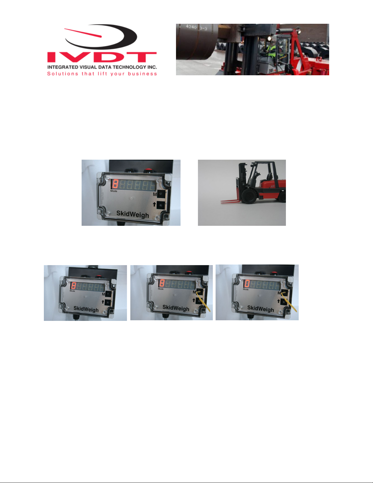
Check that software version displayed on LED is the one applicable for your application.
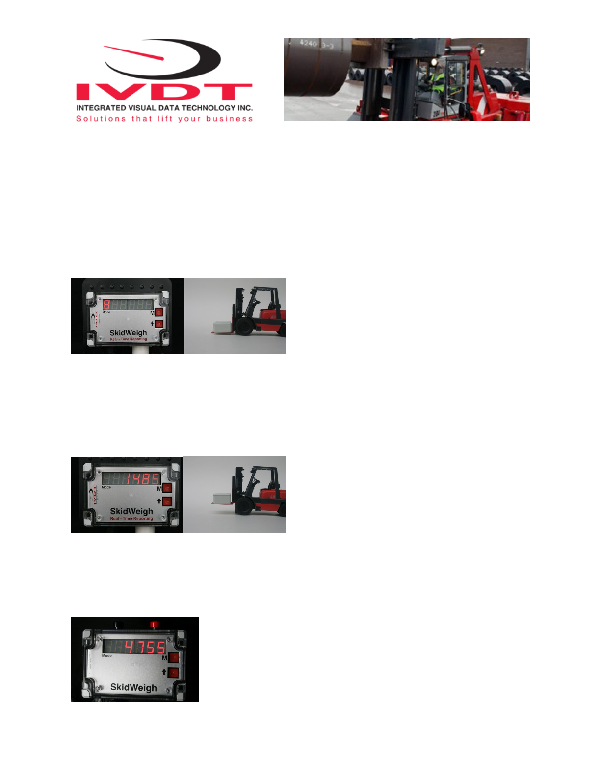
Overview of components
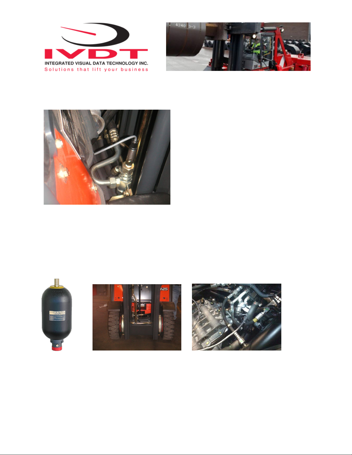
The standard ED2-AT SkidWeigh check weighing system consist of two main components:
* Digital indicator with wiring harness, mounting bracket and anti-vibration mount
* Hydraulic pressure transducer with 3 wires cable
* Installation & Calibration manual and operator usage instruction
Integrated Visual Data Technology Inc. 3439 Whilabout Terrace, Oakville, Ontario, Canada L6L 0A7

Operational principal
The ED2-AT Series SkidWeigh system operational principal is based on the hydraulic pressure transducer mounted in
the vehicle lifting hydraulic circuit that will automatically activate the “weighing cycle / specific algorithm ” every time a
skid load is lifted just above the ground. The increase in pressure is converted in an electronic signal at the sample rate of
16000 readings which is converted into a load weight reading.
Pressure transducer installation
The pressure transducer must be installed in the lifting hydraulic line between the lift control valve and lift
cylinder(s). Mount a T-piece in lifting hydraulic line. In some cases you can install the pressure transducer in the flow
divider, drilling and tapping for 1/4”-18 NPT male in spare plug (if only single or double mast configuration) or in the body
of the flow divider. Also, you can drill and tap on any “larger elbow” that might be available in the hydraulic lifting circuit
found in vehicles with larger hoses to accommodate larger vehicle lifting capacities.
Pressure transducer installation precautions
Before installation of the pressure transducer the hydraulic lift circuit must be pressure free.
There are two ways to do that:
1. Place the forks on the ground in their lowest position and make the hydraulic system pressure free by tilting the mast
forward. The chain(s) should be slack.
2. Lift the forks and position them on the top of a supporting fixture. Start lowering the lifting cylinder into its lowest
position. Be sure that chain(s) are slack.
Make sure that that installed pressure transducer will not touch any moving parts or assembly of the vehicle while in
normal operation. Pressure transducer has 1/4”-18 NPT male thread. Use thread seal to ensure tight fit.
Selecting the mounting location for digital indicator
Use the mounting bracket with the anti vibration mount and fasten digital indicator on the vehicle dashboard or side
railing preferably on the right hand side. There are many examples of mounting locations that will depend on the vehicle
model. However, additional mounting items such as a flat brackets may be needed to help secure the unit to upper right
corner of the guard or side railing.
Integrated Visual Data Technology Inc. 3439 Whilabout Terrace, Oakville, Ontario, Canada L6L 0A7

Choose the correct location and make sure that:
- Indicator is visible and within reach of the operator
- Location so that operator does not hit a head
Compact size
All of the SkidWeigh systems are compact size, housing dimension
of only 120 x 80 x 55 mm.
Electrical Connections
All SkidWeigh systems operate from 12 to 55 V DC.
Digital indicator with seven wires single cable
- Orange Wire (+) Ignition switch On position
- Brown Wire (-) Battery negative
- Red Wire, connect to RED wire of the pressure transducer cable
- Black Wire, connect to BLACK wire of the pressure transducer cable
- White Wire, connect to WHITE wire of the pressure transducer cable
Pressure transducer cable
Pressure transducer cable must be connected to the digital indicator seven wires single cable
-White Wire, signal 0 to 2,5 V
-Black Wire, signal negative
- Red Wire, power supply to pressure transducer + 11 V DC
Electrical power short circuit protection
- All of the SkidWeigh systems are internally short circuit protected with resettable fuse. There is no need to install
external inline fuse in orange wire connected to the ignition switch.
- Automotive 60 V load dump protection
- Reversal power supply protection
-Note: Any external devices connected to the SkidWeigh system, such as non standard onboard printer might require
external fuse.
Integrated Visual Data Technology Inc. 3439 Whilabout Terrace, Oakville, Ontario, Canada L6L 0A7

“Quick test to determine if electrical connections are done right”
Note: SkidWeigh weighing calibration function is not done
yet at this stage. This procedure is only to test if electrical
connections of the system installation into the vehicle is
done properly!
After you have connected electrical power and pressure
transducer cable you can “quickly” check the system
operation. - Lower the forks to the ground
- Turn On ignition switch
- Digital LED display will be activated, showing software
version and serial number
- Number 8 will be shown on LED display above the Mode
sign.
-Go ahead and lift the forks and engaged second mast to
increase pressure in lifting cylinder. Number 8will go off and some load weight will be shown on LED display.
If the above test is valid than the system electrical connections are done right. The next procedure will be to calibrate
the SkidWeigh weighing function.
Lift truck equipped with hydraulic accumulator
If the standard SkidWeigh system is installed on the lift trucks equipped with hydraulic accumulators, please contact us
to provide you with different digital indicator having specific software algorithm to obtain load weight accuracy within +/-
0.1 to 1% of vehicle maximum lifting capacity.
Weighing function calibration procedure
The ED2-AT Series SkidWeigh calibration is automatic and is done by lifting empty and loaded forks (or any other
attachment such as paper clamp) just above the ground. MAKE SURE THAT YOU HAVE A KNOWN LOAD WEIGHT
AND KEEP IT NEARBY TO COMPLETE THE CALIBRATION.
For the best results use at least minimum calibration load test weight of 30 to 50% of maximum lifting capacity of the lift
truck. Use customer floor scale or find a known skid load weight within the operational facility.
Integrated Visual Data Technology Inc. 3439 Whilabout Terrace, Oakville, Ontario, Canada L6L 0A7
Other manuals for SkidWeigh ED2-AT Series
1
Table of contents
Other IVDT Accessories manuals

IVDT
IVDT SkidWeigh Plus ED3-IM User manual

IVDT
IVDT SkidWeigh ED2E-EP Series Use and care manual

IVDT
IVDT SkidWeigh ED2-EPT Series User manual

IVDT
IVDT SkidWeigh ED7 Series Use and care manual

IVDT
IVDT SkidWeigh ED2 Series Setup guide

IVDT
IVDT SkidWeigh ED2-SSL Series User manual

IVDT
IVDT SkidWeigh ED2-EP Use and care manual