Regardless of the method you choose, ensure that the connection is mechanically sound and properly insulated. Use
high quality electrical tape and shrink tubing where necessary.
The system is connected directly to the vehicle’s ignition switch, 12 to 55 VDC. There is no on/off switch on the unit.
Electro-Magnetic Compatibility
CE conformity to EC directive 89/336 (EMC) by application of harmonized standards: Interference stability EN
61000-6-2 and EN 61326-1 interference emit EN 61000-6-3, EN 61326-1 for the pressure transducer.
ED7 Series
Our policy is one of continuous improvement and the information in this document is subject to change without notice.
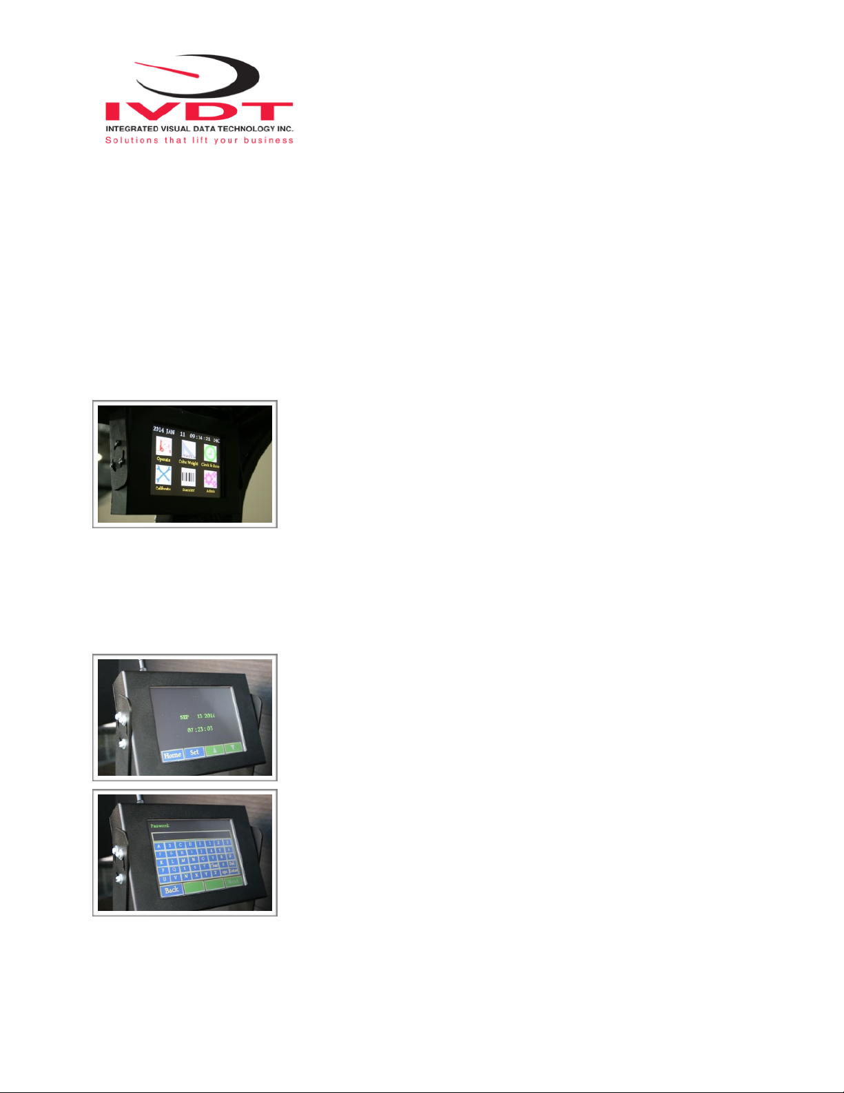
Check that software version displayed on LCD is the one applicable for your application.
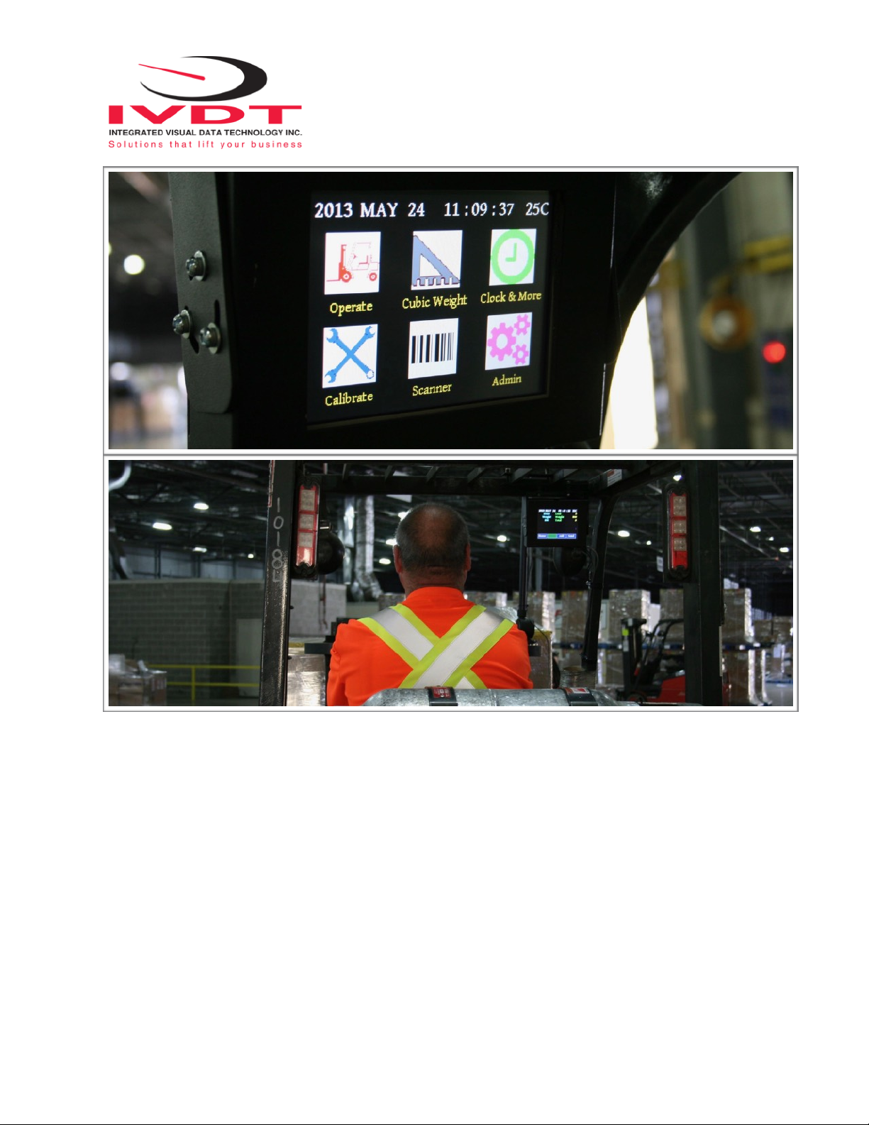
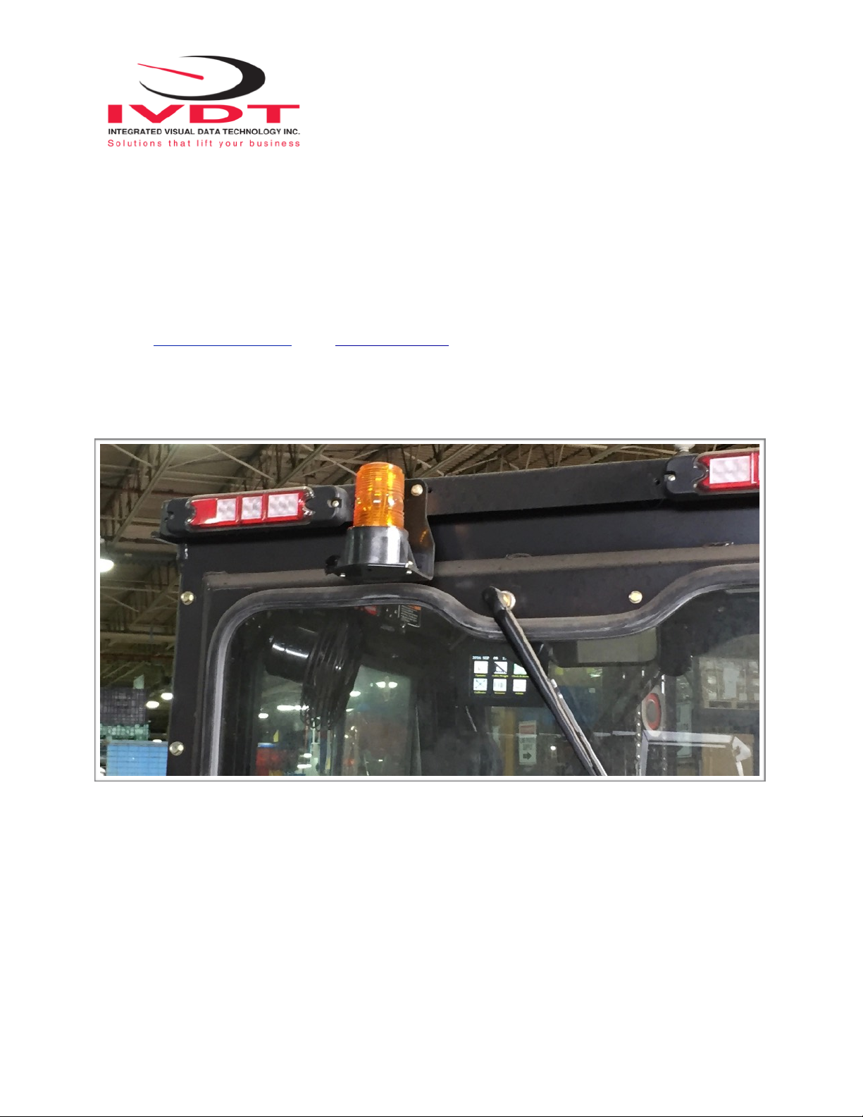
Overview of components
The standard SkidWeigh ED7 system consist of two main components:
* Digital indicator with wiring harness, mounting bracket
* Hydraulic pressure transducer with 3 wires cable
* Installation & calibration manual and operator usage instruction
Operational principal
The SkidWeigh ED7 system check weighing operational principal is based on the hydraulic pressure transducer
mounted in the vehicle lifting hydraulic circuit that will automatically activate the “weighing cycle / specific algorithm ”
every time a skid load is lifted just above the ground. The increase in pressure is converted in an electronic signal at
the sample rate of 16000 readings which is converted into a load weight reading. The ED7 system optional
equipped with the optional impact detection system have the impact module mounted inside the instrument
enclosure.
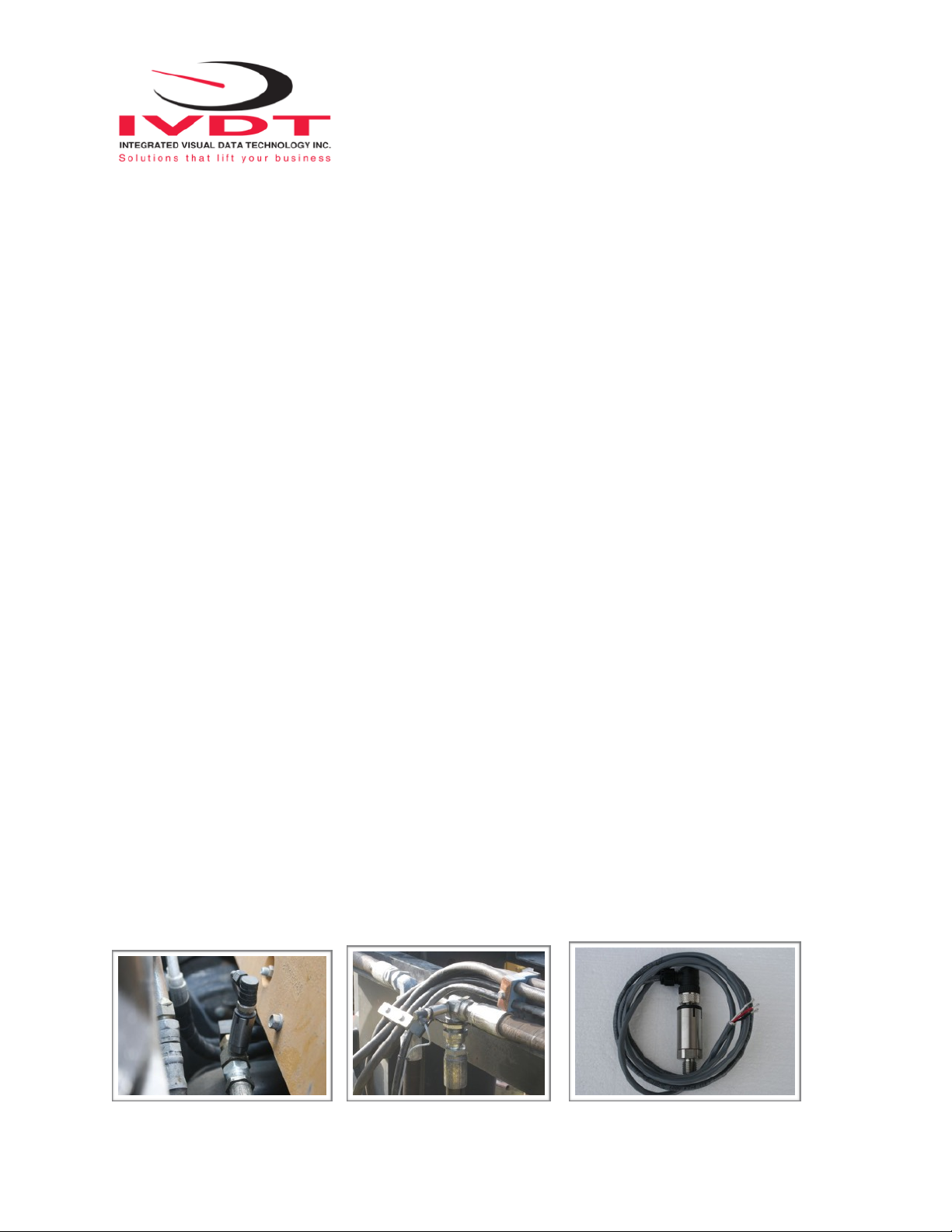
Pressure transducer installation
The pressure transducer must be installed in the lifting hydraulic line between the lift control valve and lift cylinder(s).
Mount a T-piece in lifting hydraulic line. In some cases you can install the pressure transducer in the flow divider,
drilling and tapping for 1/4”-18 NPT male in spare plug (if only single or double mast configuration) or in the body of
the flow divider. Also, you can drill and tap on any “larger elbow” that might be available in the hydraulic lifting circuit
found in vehicles with larger hydraulic hoses to accommodate larger vehicle lifting capacities.
!!