6
The seat can be adjusted as follows:
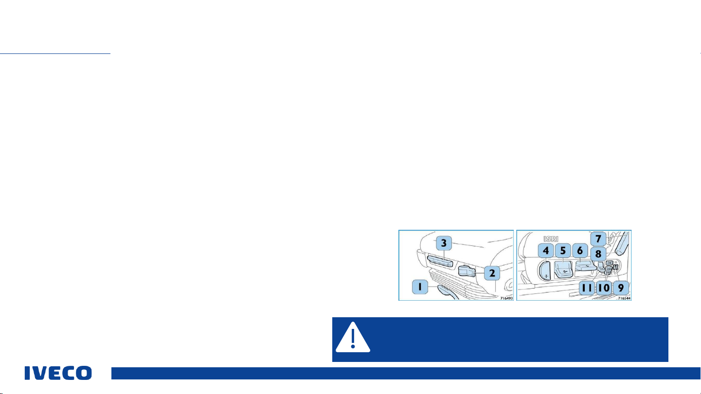
Adjustment in the longitudinal direction
▪Pull up the lever (1) to unlock the driver’s seat and push it freely forward or back; release
the lever, thereby locking it in the desired position.
Horizontal seat suspension
▪The control lever (2) of the horizontal pneumatic damper can (optionally) activate or
deactivate the horizontal isolator to absorb longitudinal impacts.
▪Lever in right position: Isolator activated
▪Lever in left position: Isolator deactivated
Adjustment of the seat back rest
▪Pull the lever (7) all the way to adjust the tilt of the back rest. Release the handle to block
the back rest in the desired tilt.
▪Shoulder adjustment(8) (optional) of the back rest: If you push the button on the top of the
lever (7), you can adjust the shoulder area of the back rest to the desired position.
Seat tilt
▪You can press the grip (5) to adjust the tilt of the seat.
ADJUSTING THE DRIVER’S SEAT
General specifications: The seat may only be adjusted when the vehicle is stopped;
afterwards, you must ensure that the seat has snapped into the desired position. If the
specification is not complied with, there is a significant health risk and the risk of
serious vehicle damage.
Adjusting the seat height
▪Pull the lever (6) up to lift the seat upward.
▪Push the lever (6) down to lower the seat. The higher the seat is lifted, the longer the spring
deflection will be. The hardness can be adjusted via the controller for “adjusting the seat
damper”.
Adjusting the seat damper (optional)
▪Pull the lever (11) up for softer suspension. Push the lever (11) down for harder
suspension. Continuous adjustment.
Lowering the seat (quickly venting air)
▪Press the button (4) down to move the seat to the lowest position. This makes it easier to
get in and out.


 Operator's manual")


