Ivoclar digital PrograMill Base User manual

ivoclardigital.com
PrograMill Base
Operating Instructions


Table of Contents
3
Table of Contents
1 About this Document 5
1.1 Target groups 5
1.2 Signs and symbols 6
1.3 Revision and validity 7
1.4 Supporting documents 7
2Safety 8
2.1 Intended use 8
2.2 Hazardous areas on the PrograMill Base 9
2.3 Safety instructions for individual operating phases 10
3 Design and Function 11
3.1 Complete system 11
3.2 Overview of PrograMill Base 13
3.3 Suggestion for the placement of items within the drawer 15
4 Transportation and Assembly 17
4.1 Choosing the location site 17
4.2 Transportation of the PrograMill Base 17
4.3 Unpacking the PrograMill Base 18
4.4 Checking delivery contents and condition 18
5 Initial Operation 19
5.1 Setting up the PrograMill Base 19
5.2 Placing the PrograMill milling machine onto the PrograMill Base 20
5.3 Setting up the PrograMill accessories 22
6 Cleaning 26
7 Technical Data 27
7.1 Measurements, weight 27
7.2 Ambient conditions 27

About this Document
5
1 About this Document
These Operating Instructions will familiarize you with the PrograMill Base features. The
PrograMill Base will be referred to as “base cabinet” from now on.
This product is a cabinet for accessories, tools and discs / blocks from the PrograMill milling
systems.
The Operating Instructions are an integral part of the product. They describe the safe and
correct use in all operating processes.
Improper use can be dangerous. Please observe the relevant safety instructions and read the
Operating Instructions carefully.
These Operating Instructions only apply together with the Operating Instructions from the
milling systems PrograMill PM3, PM5 and PM7 (“Supporting documents”, page 7). Read the
instructions carefully before using PrograMill Base, in particular the chapter regarding safety
instructions and warnings.
Should you lose these Operating Instructions, you can download them from
www.ivoclarvivadent.com.
For all types of technical questions, please contact your authorized service partner.
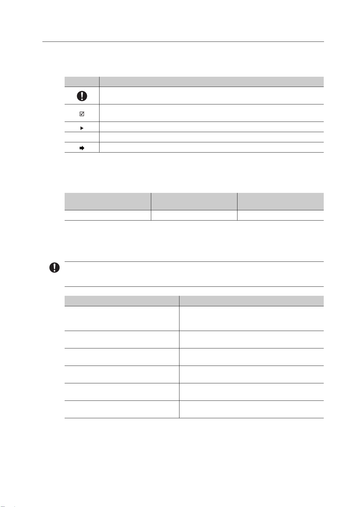
1.1 Target groups
Target group Duties
Operator •Keep these Operating Instructions
available at the place where the unit is
operated, also for future use.
•Request personnel read and observe
these instructions and the applicable
documents included. This applies in
particular for the safety instructions and
warnings (“Safety”, page 8).
•Observe additional product-related
stipulations and regulations.
Dental technician •Read and observe these Operating
Instructions and the applicable
documents, in particular safety
instructions and warnings (“Safety”,
page 8).
Qualified dental staff
CNC technician
Authorized Ivoclar Vivadent service partner

About this Document
6
1.2 Signs and symbols
1.2.1 Warnings
Warnings are used in these Operating Instructions to warn you of a risk of injury to persons
and/or damage to property.
1. Always read and observe these warnings.
2. Follow all measures marked with the warning symbol and warning word.
Depending on the severity and probability of the danger, the following warning levels are
distinguished:
Clarification of the structure of a warning:
WARNING! Name of source of danger, cause of hazard or type of risk.
Consequences of non-compliance with instructions.
Action in order to avoid danger.
Hazard example:
WARNING! Risk of injury from the PrograMill Base tipping over or falling down.
Crushing extremities.
Damage to the PrograMill Base.
Only use suitable means of transportation (e.g. fork lift trucks, capacity > 500 kg).
Secure the PrograMill Base with suitable transport straps to prevent falling (e.g. tension
belts).
Avoid impact, jerky movements and vibration during transportation.
Stay well clear of suspended loads or raised parts.
Warning
symbol Warning word Danger level
Consequences resulting
from non-observance
DANGER Immediate imminent
danger
Death, severe personal
injury
WARNING Potential danger Death, severe personal
injury
CAUTION Potential danger Slight personal injury
- NOTICE Potential danger Damage to property

About this Document
7
1.2.2 Signs and symbols
1.3 Revision and validity
1.4 Supporting documents
You can obtain information about the applicable documents from your local sales partner or
in the download area of Ivoclar Vivadent at: http://www.ivoclarvivadent.com.
Symbol Significance
Additional information, e.g. for better understanding, for simplifying
workflows or for further information
Prerequisite which must be followed before the subsequent actions can be
performed
Individual steps which you must perform
1., 2. Several steps that you must perform in the given order
The result indication of an operation step or several steps, for success control
Version Date
Amendments to the
previous version
1.0 30-11-2017 Initial creation date
Document Clarification
Checklist for your PrograMill system Information about requirements that must be
observed for transport, installation and use of
the PrograMill system
Operating Instructions PrograMill PM3 Instructions on operating the milling machine
PrograMill PM3 and the PrograMill Tank
Operating Instructions PrograMill PM5 Instructions on operating the milling machine
PrograMill PM5 and the PrograMill Tank
Operating Instructions PrograMill PM7 Instructions on operating the milling machine
PrograMill PM7 and the PrograMill Tank
Operating Instructions PrograMill
Suction Unit
Important information about the use of the
PrograMill Suction Unit (optional)
Safety Data Sheet PrograMill Fluid Important information about the use of the
PrograMill Fluid coolant concentrate

Safety
8
2Safety
These Operating Instructions only apply together with the Operating Instructions from the
milling systems PrograMill PM3, PM5 and PM7 (“Supporting documents”, page 7). Read the
instructions carefully before using PrograMill Base, in particular the chapter regarding safety
instructions and warnings.
WARNING! Improper use of the product.
Danger to the user.
The safety chapter contains important information on the safety of the product: Please
read thoroughly prior to use.
The product is built according to state-of-the-art technology and recognized safety
regulations. Nevertheless, its use could constitute a risk of injury of the user or third party or
possibly cause impairment to the product and other property.
2.1 Intended use
PrograMill Base is designed for use in the dental technical field as a place to stand the
PrograMill PM3, PM5 or PM7 milling systems and store accessories, cleaning materials, tools
and discs / blocks. Use the PrograMill Base exclusively for this purpose.
In the case of damage caused by improper use or failure to observe the Operating Instructions,
all liability and warranty claims are void.
2.1.1 Potential improper use
Equipment, accessories and components whose weight exceeds the load-bearing capacity of
PrograMill Base and built-in pull-out shelf must not be placed on or in PrograMill Base.
The following is considered as misuse of the system:
•Non-compliance with the intended use, intended operator specifications or intended
environment
•Modifications, maintenance and repairs without the permission of Ivoclar Vivadent
•Operation with unsuitable parameters
Improper use of the PrograMill Base can lead to the following:
•Danger for operating personnel
•Impairment of the operability of the PrograMill Base
Ivoclar Vivadent assumes no liability for damage resulting from improper use.

Safety
9
2.2 Hazardous areas on the PrograMill Base
No. Hazardous areas Safety measures Protective effect
1 Pull-out shelf Lock on the handles Secures against unintentional
movement when doors are opened
or work is carried out on the
PrograMill milling machine or
PrograMill Base.
11

Safety
10
2.3 Safety instructions for individual operating phases
2.3.1 Transportation
Only transport the PrograMill Base according to the description in these Operating
Instructions (“Transportation and Assembly”, page 17).
2.3.2 Use
Keep unauthorized persons, such as patients, children and animals, away from the
product.
Do not use a damaged, non-functioning product or accessories, instead notify the
authorized service partner.
To ensure the stability of the PrograMill system, only operate the CNC milling machine
with a crossbeam mounted on the PrograMill Base.
2.3.3 Improper maintenance, modifications and repairs
Improper service and improper repairs or modifications will endanger users and result in
damage to the product.
Should you carry out any maintenance to the system or modifications to the product without
prior written consent by an authorized service partner, all warranty claims are void.
Maintenance and repair of damaged safety equipment or other parts of the PrograMill
Base should only be performed by an authorized Ivoclar Vivadent service partner.

Design and Function
11
3 Design and Function
3.1 Complete system
2
5
4
3
1

Design and Function
12
No. Description Function
1 PrograMill Base cabinet •Installation site for the milling
machine
•Storage of accessories, tools and
discs / blocks
2 CNC milling machine PrograMill PM7
(exemplary for PrograMill series
including PM3, PM5, PM7)
Milling of discs / blocks
3 PrograMill Suction Unit (optional) Extraction of milling dust, milling
vapours and other dental material
particles in dry operation
4 PrograMill Suction Unit separator
(optional)
5 PrograMill Tank and Filter Wet operation:
•Part of the coolant fluid circuit, intake
and delivery of the coolant fluid
•Filter for the used coolant fluid
before it is (re-)used in the milling
chamber

Design and Function
13
3.2 Overview of PrograMill Base
The PrograMill Base has been specifically designed to meet the needs of the PrograMill
systems. It has sufficient load-bearing strength to support the PrograMill milling machines
and their accessories and is designed to store discs / blocks and tools.
14 13 11
1
2
4
5
6
7
8
1012
3
9
10

Design and Function
14
No. Description Function
1 Pull-out shelf with indentations (in the
illustration part of the front panel has
been faded out for better visibility)
•Holds the PrograMill Suction Unit
•The indentations ensure proper
positioning of PrograMill Suction
Unit
2 Exhaust air outlet Removal of exhaust air to the
PrograMill Suction Unit
3 Service wheels Only for the service partner
4 Drawer Storage of tools, discs / blocks and
cleaning agents
5 Storage space Position for the milling machine
6 Indentations for device feet Secure positioning of the milling
machine on the PrograMill Base
7 Tube and cable access Cable and tube guides
8 Handle Pulling the shelf out and pushing it
back in
9 Tube holder The water outlet tube and the water
inlet tube are attached in the tube
holder during cleaning and
maintenance work
10 Lock Securing the pull-out shelf against
unwanted movement
11 Device feet Height adjustment of the PrograMill
Base cabinet
12 Energy chain •Laying cables and tubes
•Kink protection for cables and tubes
13 Wheels Pulling the shelf out and pushing it
back in
14 Crossbeam Ensures the stability of the PrograMill
system

Design and Function
15
3.3 Suggestion for the placement of items within the drawer
You can store the accessories for your PrograMill system in the drawer of the PrograMill Base
cabinet as follows:
The following picture shows an assembly example for the components supplied with the
PrograMill PM7 milling machine.
Further information on the scope of delivery of your respective PrograMill milling machine
can be found in the operating instructions for the device (“Supporting documents”, page 7).
21 93 4 6 75 8

Design and Function
16
No. Description
1 PrograMill disc holder for PM3, PM5, PM7
2 Torque wrench
•0.45 Nm for all zirconium oxide and wax materials
•2.8 Nm for all PMMA materials and non-precious metals
3Disc
4 Tool disc with tools for the milling machine without interchangeable tool
magazine
(optional, estimated to be available from Q4/2018)
5 PrograMill tool pliers
6 Tool magazine (optional, available for PrograMill PM7, use supplied foam insert,
see “Delivery form”, page 28)
7 Foam insert for tool magazine (only for PrograMill PM7)
8 Used Tool Library with labelled matrix for accommodating used tools
9 Spindle maintenance set

Transportation and Assembly
17
4 Transportation and Assembly
Transportation and assembly are carried out by your sales or service partner and a Digital
Instructor as part of your PrograMill System Instruction.
Do not perform the tasks described below alone!
4.1 Choosing the location site
Before setting up the PrograMill Base, select a suitable location site for your device.
Make sure the following requirements are complied with:
Place the PrograMill Base on a stable, level, non-slip and clean surface (load bearing
capacity min. 500 kg).
Further information on choosing a suitable site can be found in the operating instructions for
the PrograMill milling machine and in the checklist for your PrograMill system (“Supporting
documents”, page 7).
4.2 Transportation of the PrograMill Base
WARNING! Risk of injury from the PrograMill Base tipping over or falling down.
Crushing of extremities.
Damage to the PrograMill Base.
Only use suitable means of transportation (e.g. fork lift trucks, capacity > 500 kg).
Secure the PrograMill Base with suitable transport straps to prevent falling (e.g. tension
belts).
Avoid impact, jerky movements and vibration during transportation.
Stay well clear of suspended loads or raised parts.

Transportation and Assembly
18
WARNING! Risk of injury due to heavy lifting.
Injuries to the back due to overloading.
Only lift the PrograMill Base with the aid of a fork lift.
Unpack the PrograMill Base after transportation.
Move the product in its original packaging by means of a fork lift to the defined location
site.
4.3 Unpacking the PrograMill Base
WARNING! Risk of injury from heavy lifting, falling over or dropping the PrograMill Base.
Crushing of extremities.
Injuries to the back due to overloading.
Lift the PrograMill Base with at least 4 persons from the Euro pallet.
The PrograMill Base is delivered on a Euro pallet.
Location site selected (“Choosing the location site”, page 17)
1. Cut the transport bands with scissors.
2. Remove the transport box.
3. Open the PrograMill Base doors.
4. Open the lock on the handles of the
pull-out shelf (“Overview of PrograMill
Base”, page 13).
5. Lift the pull-out shelf (1). Remove it
from the cabinet over the crossbeam (2).
6. Lift the PrograMill Base from the Euro
pallet.
4.4 Checking delivery contents and condition
1. Unpack the product after delivery (“Unpacking the PrograMill Base”, page 18).
2. Check that all contents are complete (“Delivery form”, page 28).
3. Check all components for transport damage.
4. Report any transport damage or missing components immediately.
1.
1.
2.
2.2.

Initial Operation
19
5 Initial Operation
The set-up is carried out by your sales or service partner and a Digital Instructor as part of your
PrograMill System instruction.
Do not perform the tasks described below alone!
If you need to move the PrograMill system due to renovation or relocation, please contact
your sales or service partner first.
5.1 Setting up the PrograMill Base
A set of rolling wheels have been included in the delivery (part (3) in the picture in section
“Overview of PrograMill Base”, page 13) to make moving the PrograMill Base easier during
renovation, cleaning and maintenance work within the laboratory.
In order to move the PrograMill Base using the wheels during later transportation, screw the
standing feet out as far as possible so that the rolling wheels can be fitted.
Then screw the standing feet back in so that the weight of the PrograMill Base is no longer
supported by the feet, but by the rolling wheels. The PrograMill Base can now be moved using
the wheels. After the cabinet has been placed into the correct position, repeat the above steps
in reverse order to disassemble the rolling wheels.
WARNING! Risk of injury due to the PrograMill Base rolling away or the PrograMill milling
machine falling down due to unsecured rolling wheels.
Crushing of extremities.
Damage to the PrograMill milling machine.
Before placing the PrograMill milling machine on top of the PrograMill Base, unscrew the
standing feet so that the weight of the machine rests exclusively on the feet, not on the
mounted rolling wheels.
Then, disassemble the wheels and store for later use.
NOTICE! Damage to cables and tubes.
Defective or damaged PrograMill Suction Unit.
Adjust the feet so that the distance between the sides of the PrograMill Base and the floor
is at least 15 mm.

Initial Operation
20
Location site selected (“Choosing the location site”, page 17)
PrograMill Base unpacked (“Unpacking the PrograMill Base”, page 18)
1. Set up the PrograMill Base in the chosen location site.
2. Adjust the height of the feet using the Allen key according to the above specifications.
3. Use the spirit level to check whether PrograMill Base is perfectly level.
4. Loosen the Allen screws (1) and remove
the crossbeam (2).
5.2 Placing the PrograMill milling machine onto the PrograMill Base
WARNING! Risk of injury from the PrograMill Base tipping over or falling down.
Crushing of extremities.
Damage to the PrograMill milling machine.
Only use suitable means of transportation (e.g. fork lift trucks, capacity > 500 kg).
Secure the PrograMill milling machine with suitable transport straps to prevent falling
(e.g. tension belts).
Avoid impact, jerky movements and vibration during transportation.
Stay well clear of suspended loads or raised parts.
Always move the PrograMill milling machine from the fork lift truck to the location site
with at least 6 people (weight of the milling machine approx. 210 kg).
WARNING! Risk of injury due to heavy lifting.
Injuries to the back due to overloading.
Only lift the PrograMill milling machine with the aid of a fork lift truck.
2.
2.
1.
1.
Other manuals for PrograMill Base
1
Table of contents
Other Ivoclar digital Dental Equipment manuals