3
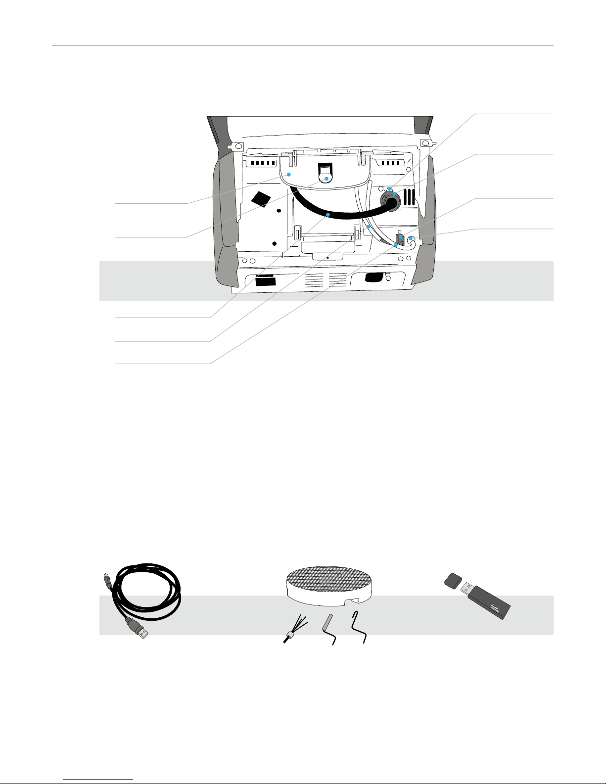
List of parts 4
1. Introduction / Signs and Symbols 7
1.1 Introduction
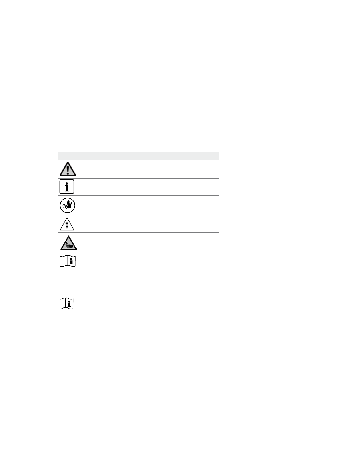
1.2 Signs and symbols contained in these Operating Instructions
1.3 Notes regarding the Operating Instructions
1.4 Notes on the different voltage versions
1.5 Notes on the images in the Operating Instructions
2. Safety First 9
2.1 Indications
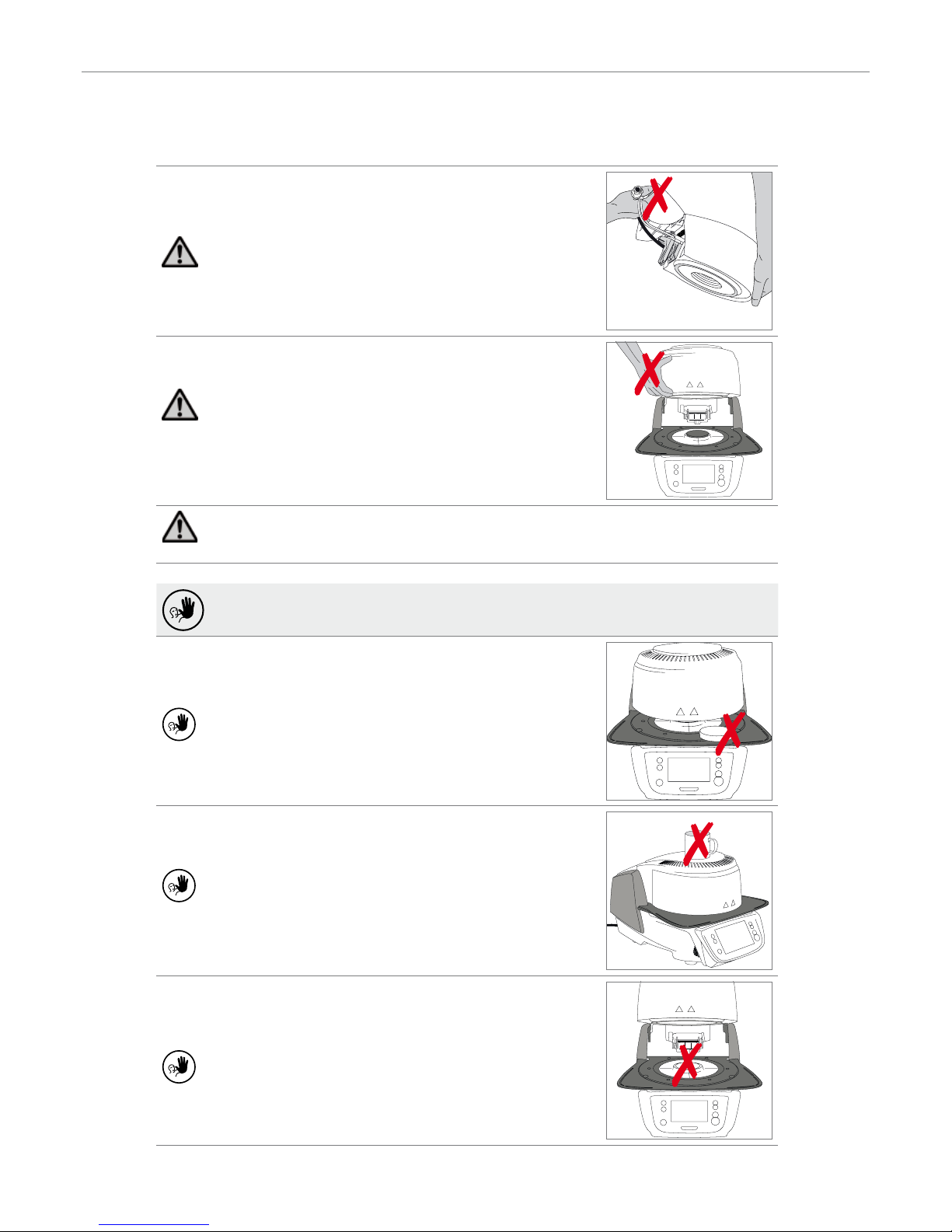
2.2 Health and safety instructions
3. Product Description 14
3.1 General aspects
3.2 Hazardous areas and safety equipment
4. Installation and Initial Start-Up 15
4.1 Unpacking and checking the contents
4.2 Selecting the location
4.3 Assembly
4.4 Removing the furnace head
4.5 Initial start-up
5. Operation and Configuration 22
5.1 Introduction to the operation
5.2 Firing programs and programming options
5.3 Advanced functions of the furnace
6. Practical Use 50
6.1 Firing with an Ivoclar Vivadent program
6.2 Firing with an individual program
7. Maintenance, Cleaning, Diagnosis 53
7.1 Monitoring and maintenance
7.2 Cleaning
7.3 Service note
7.4 Stand-by
7.5 Power-saving mode
8. What If ... 55
8.1 Error messages
8.2 Additional error messages
8.3 Technical malfunctions
8.4 Repair
8.5 Resetting to factory settings
9. Product Specifications 61
9.1 Delivery form
9.2 Technical data
9.3 Acceptable operating conditions
9.4 Acceptable transportation and storage conditions
10. Appendix 63
10.1 Program table
Table of Contents