10
2.1.6
Contraindication
Never use the furnace without the
sinter tray. Use only the original S1
sinter tray. Do not use the firing trays
or honey-combed trays from conven-
tional ceramic furnaces. Furthermore,
check the sinter tray for damage, cracks
or contamination before every sintering
cycle. If the table is damaged, it must no
longer be used. A maximum of one
sinter tray is to be placed in the
sintering chamber. Do not stack the
sinter trays.
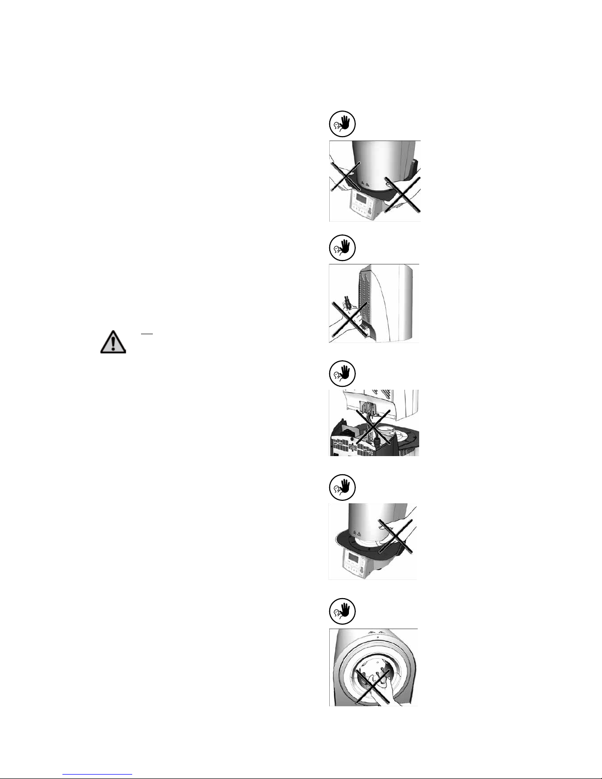
2.1.7
Contraindication
Firing trays must not be placed in the
area surrounding the firing table, since
this will obstruct the closing of the fur-
nace head.
2.1.8
Contraindication
Foreign objects must not be placed on
the furnace head or the air vents.
Make sure that no liquids or other for-
eign objects enter the air vents, since
this may result in an electrical shock.
2.1.9
Contraindication
Make sure that no liquids or other
foreign objects enter the furnace.
2.1.10
Contraindication
Do not insert any foreign objects into
the air vents. There is a risk of
electrical shock.
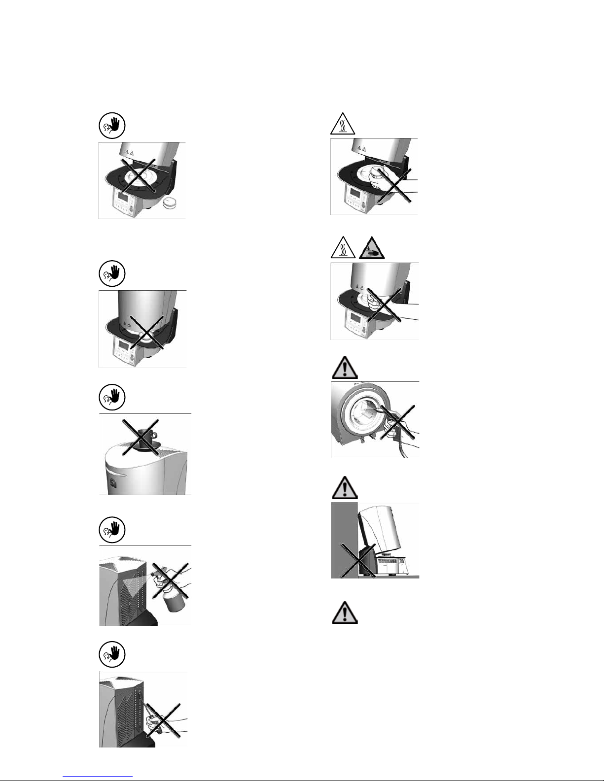
2.1.11
Burn hazard
Never place objects in the sintering
chamber by hand, since there is a burn
hazard. Always use the sinter tray fork
(accessories) supplied for this purpose.
Never touch the hot surface of the
furnace head, as there is a burn
hazard. Please also refer to the
warnings on the furnace.
2.1.12
Risk of crushing and burn hazard
Never reach under the furnace head
with the hand or other parts of the
body during operation, since there is a
risk of crushing and a burn hazard.
2.1.13
Risks and dangers
This product contains ceramic fibres
and may release fibre dust. Do not use
compressed air, or blow, on the
furnace, thus distributing the dust in
the environment, and observe the
additional notes on page 11.
2.1.14
Risks and dangers
Do not use the furnace without
spacer, since the distance to the back
wall has to be kept!
2.1.15
Risks and dangers
The furnace must not be operated if the heating element
in the sintering chamber is damaged. There is a risk of
electric shock upon contact with the heating wire.