12 13
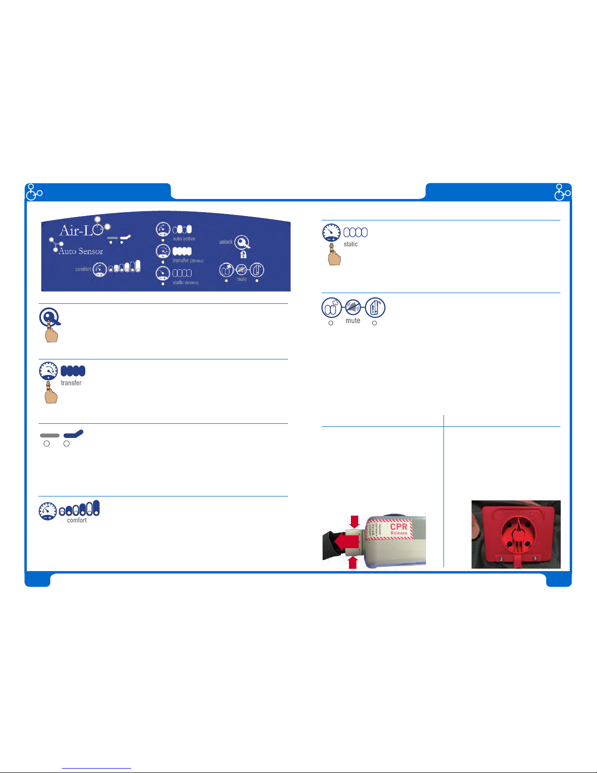
Control Unit Operation
Unlocking the system
After start up, or after 5 minutes without user input, the system will
automatically lock to prevent tampering. The Unlock LED will light up
to indicate this. To change any settings, simply press AND HOLD the
Unlock Button for 2 seconds then release to activate controls.
Positioning or transferring patient on bed
To position the patient on the mattress or to generally
manoeuvre or transfer the patient, press the transfer button.
This will inflate the mattress to maximum pressure and
provide a stable surface. The system will automatically revert to the
previous mode after 20 minutes.
Auto Patient Profiling
The system is programmed to automatically sense the profile
of the patient - when the sensor in the head end of the
mattress detects more than 20 degrees incline then it will
switch to incline mode and automatically add more pressure into the mattress.
Note: only provide the minimum incline necessary for intubation or feeding
- excessive inclines can limit the effectiveness of the mattress.
Auto Sensor Adjustment
After initial inflation, the system will automatically enter a
weight detect mode. During this 7 minute period, all
comfort lights will flash on and off. If a patient is on the
mattress at this time, then the system will auto calculate the correct pressure
setting. This auto detect mode can be used at any time by pressing the comfort
button once only. It is best if the system is in static mode and the patient is
totally reclined for more accuracy. The auto setting can be overridden at any
time by pressing and holding the comfort button and then manually selecting.
Control Unit Operation
Static Mode
Static mode can be selected to cease any alternation
whilst remaining at the programmed or selected comfort
setting. This can be beneficial for meal breaks when the
bed is inclined for back support. It gives a stable surface
and a break from therapy. Static Mode will automatically
revert back to Active Mode after 1 hour.
Alarms and Diagnostics:
The control unit features an audio visual alarm
diagnostic which will activate if there is a malfunction.
If the left button flashes and alarms, it indicates that
there is a problem with the mattress or an air leak inside the control unit. If
the right button flashes and alarms, it indicates that there is an electrical or
mechanical malfunction within the control unit itself.
Both these audio alarms can be silenced by pressing the mute button.
This will mute the alarm for 20 minutes. If the malfunction has not been
resolved however, the alarm will re-activate.
For more information on alarms and faults with the system, please see the
Troubleshooting section of this manual.
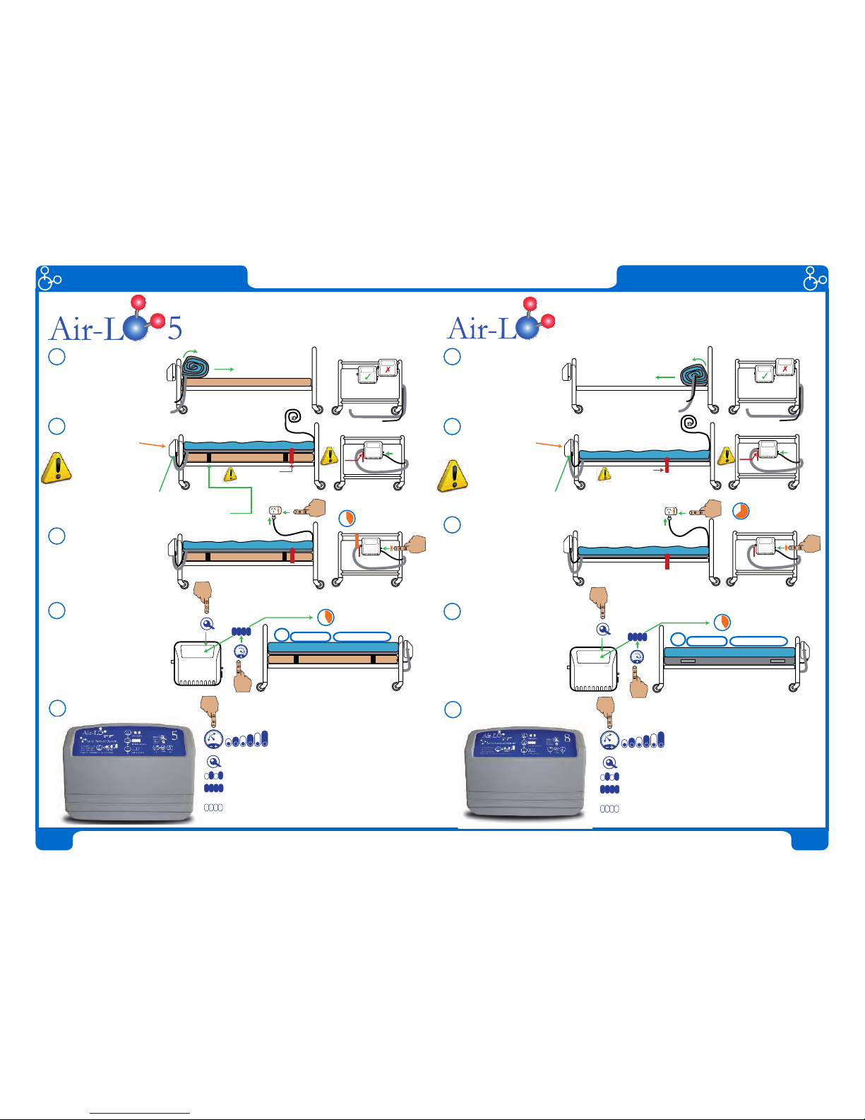
CPR Operation - AirLo3 CPR Operation - AirLo5/AirLo8
1
1
2
The CPR operation of this system
is located at the Control Unit. It
is designed to be easy to find and
activate quickly in the event of a CPR
emergency.
Step 1: Squeeze side levers.
Step 2: Whilst both side levers are
still squeezed, pull out to detach.
The CPR operation for these systems
is located along the right hand side
of the mattress near the head end. A
red location tag indicates its position.
Step 1: Locate the tag and lift the
flap to expose the CPR twist valve.
Step 2: Twist right to “CPR” position