iWALKFree iWALK 2.0 User manual
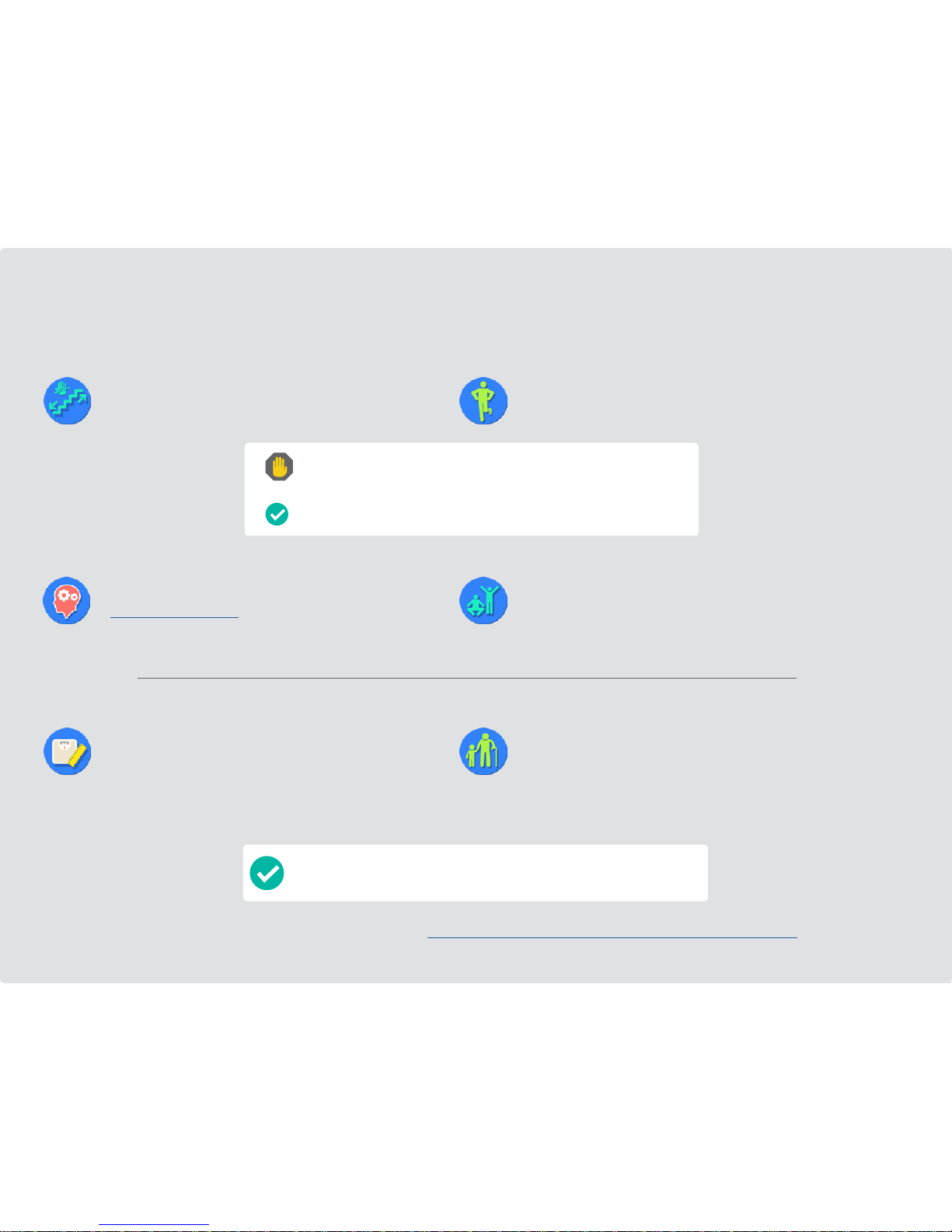
Before you start! Is iWALK 2.0 right for you?
Physical Abilities Requirements
Other Requirements
Sizing Limitations Age Limits
• If you cannot perform both of these tests, then iWALK2.0 is not going to
work for you. Please contact us for a return authorization number.
• If youcanperformboth,thencontinuereviewing theremaining requirements.
1. Stair Test
Before your injury, could you uidly walk up and down stairs at
normal speed, without using the hand rail?
• You commit to reading and following all of the instructions in this
manual or in our video tutorials at
www.iwalk-free.com/help
• You're willing to allow 5-20 minutes to allow your body to learn and
adapt to using the iWALK2.0
• Height - You are between 4'10" and 6'6", however, leg length
proportions vary considerably, so if you are under 5'1" and above
6'1" consult our sizing chart on page 3
• You weigh 275lbs (125kg) or less
• Your thigh circumference at the top of your leg is 28" (71cm) or less
2. Balance Test
Can you balance on one foot for at least 30 seconds?
• Before your injury, you could walk normally without assistive devices
• Your injury is below the knee and your uninjured leg is fully functional
• You can bend your injured leg 90 degrees at the knee
If you're over 55, pay careful attention - iWALK2.0 might not work for you.
Physical ability is more important than how old you are. And it varies from
person to person, especially as we age.
So regardless of your age, if you do not meet ALL the requirements listed above,
then iWALK2.0 isn't going to work for you.
If you meet the requirements listed above, iWALK2.0 will work for you.
More details on qualications can be found at http://www.iwalk-free.com/hands-free-crutches/how-to-use/

iWALK 2.0 SIZE CHART - based on user's height
iWALK 2.0 SIZE CHART - based on user's leg length
If your height falls into either of the blue sections in the chart on the left, there’s a
95% or greater chance the iWALK2.0 will t you, but before you buy, conrm it will
t using the Leg Length Chart below.
Measure both upper and lower leg as shown. If you fall within the ranges shown,
iWALK2.0 will t you, no matter what your height is.
Still not sure?
If you are not certain that iWALK2.0
is right for you, contact our technical
support at 562 653-4222 or e-mail
your inquiry to info@iwalk-free.com
5’1” to 6’1”4’10”to 5’1” 6’1” to 6’6”
155.0 cm to 185.5 cm
The iWALK2.0 will t you.
Review the Leg
Length Diagram
below.
Review the Leg
Length Diagram
below.
147.5 cm to 155.0 cm 185.5 cm to 198.0 cm
Leg Length
(Crotch to
floor)
Upper Leg Length
Lower Leg Length
min 12.00” (30.5 cm)
max 18.00” (46.0 cm)
min 25.75”
(65.5 cm)
max 38.00”
(96.5 cm)
min 13.75” (35.0 cm)
max 20.00” (51.0 cm)
Side Front
IWALK 2.0 LEG LENGTH DIAGRAM
• More info about sizing
• Why do Upper and Lower leg
lengths matter?
• iWALK2.0 Capacities
• Potential Knee Comfort Issues
Extra links:
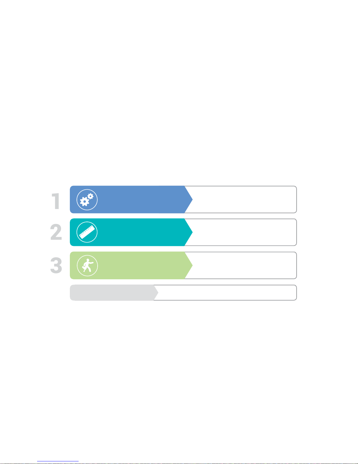
LEARN TO USE YOUR iWALK 2.0 IN
3 EASY STEPS
ASSEMBLY
FITTING
USE
Repackaging
1
2
3
5 to 7
8 to 17
18 to 25
26 to 30
Index 4

STEP 1
With the Handle facing forward, insert the Upper Assembly tubes
into the sockets of the Knee Platform.
Push down rmly on the
Handle to make sure both
tubes are fully bottomed out
in the sockets. You may have
to pull down on the left side
tube in order for it to reach the
bottom.
Make sure that the holes at
the bottom of the tubes align
with the holes in the side of
the Knee Platform.You may
need to pull down and/or rotate
the left side tube for it to align.
WARNING – do not
continue with assem-
bly unless both left and
right side holes have
aligned.
Assembly
Instructions
WANT TO LEARN FASTER? View our instructional video on how
to assemble your iWALK2.0 at www.iwalk-free.com/help
Assembly 5
Upper Assembly Lower Assembly
3. Handle
2. Thumb Screws
12. Knee Platform
13. Calf Strap Mount
14. Height Adjustment
Spring – Lower
5. Height
Adjustment
Spring – Upper
4. Nut (underside
thigh support)
15. Foot
7. Support Tubes
8. Clamp
8a. Clamp Bolt
8b. Clamp Nut
9. Thigh Strap
1. Thigh Support
6. Gate Strap
10. Knee Strap
11. Calf Strap

STEP 3
STEP 2
Attach the Lower Assembly to the Knee
Platform by pressing in the spring head
at the top of the Lower Assembly tube
and inserting the tube into the socket
of the Knee Platform. Grasping the tube,
pull down forcibly to insure that the two
parts are securely locked together.
A) Identify the Right side Support Tube by the small“R” stamped near the top.
B) While pushing down on the Upper Assembly tube , press in the silver spring head and insert the
Support Tube into the bottom of the Knee Platform socket until the spring head engages in the
holes of the Upper Assembly tube AND the Knee Platform. All three must be locked together.
C) Test the connection by rmly grasping the Upper Assembly tube with one hand and the Support
Tube with the other and forcibly try to pull them apart. If you cannot pull them apart, you have
assembled the three components correctly.
D) Insert the Left side Support Tube using the same procedures. You may need to rotate the tube
in order to align the hole.
CBA
WARNING – Aggressively test both connections (left and right). If the Support Tube, Knee
Platform and Upper Assembly tubes are not locked together, instability and injury can result.
Assembly 6

STEP 4 STEP 5
Insert the Thumb Screw into the slot on either side of the top of the Handle. Align
the hole in the top of the Thigh Support with the threaded end of the Thumb Screw.
Thread theThumb Screw into the nut located on the underside of theThigh Support
(you can see it from underneath). Do not fully tighten yet, you should be able to
rotate the Thigh Supports in and out.
Note – If the Thumb Screw will not fully tighten, check the underside of the
Thigh Support and make sure there is a silver nut nested in the hex shaped
cavity. Be careful not to accidentally push this nut out when pushing the
Thumb Screw down.
If you lose the nut, don’t panic – you can call us for a replacement or nd one at a
local hardware store. The specication is M5 x .8 (metric, 5mm, .8 pitch)
Note – Clamp should be centered between the
Support Tube ends. Realign if necessary using
a screwdriver or similar.
The Clamp should be
positioned between
the at ends of the
Support Tubes. If
not, you can remove
the Support Tube
and reinstall. Gently
push on the ends of
the Support Tubes
to align the holes
with the hole on the
Clamp, then insert
the Clamp Bolt and
secure with the Clamp Nut. Do not tighten yet.
Thumb
Screw
Nut
Assembly 7

STEP 1
Fitting
Instructions
Make sure that Thigh Supports can rotate
freely. If necessary, loosen Thumb Screws.
Proper t is essential!But it’s also easy. Get these three things right and you’ll be
iWALKing in minutes. We’ll show you how.
Height
Adjust both the upper
and lower section of the
crutch to the correct
height.
Tight
For control and stability,
you want the straps tight!
Really, really tight!
Vertical Alignment
Essential for quick
learning, and often
overlooked, the vertical
angle controls where the
foot will be positioned.
WANT TO LEARN FASTER? View our instructional video on how to
t your iWALK2.0 at www.iwalk-free.com/help
Fitting 8

STEP 2
Foot Positioning (for Left or Right) - Position the Foot so that
the curved edge is toward the outside of your leg. To reposition
the foot,
1. Loosen the Clamp Bolt.
2. Press in the height adjustment springs as shown below.
3. Continue pressing; simultaneously grasp and rotate the Foot
180 degrees until the spring heads pop out of the adjustment
holes.
Note - The Foot and lower tube will rotate . The upper
tube stays stationary.
Right Foot
Incorrect Correct
Incorrect Correct
Left Foot
Improper orientation of the Foot causes instability which
could result in a fall and/or injury.
Loosen Clamp Bolt rst
180˚
Fitting 9
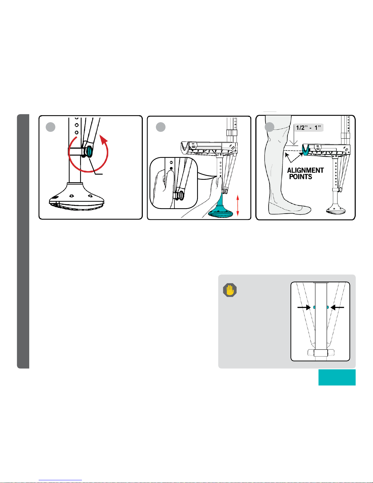
STEP 3
Lower Leg Height Adjustment - The“V”at the back of the Knee Platform
should align with a point ½” – 1” below the bottom of your kneecap.
This will result in your iWALK leg being slightly shorter than your human
leg. If in doubt about the correct height setting, it’s better to adjust the
crutch slightly too low than too high.
To adjust the height:
A) Loosen the Clamp Nut and Bolt.
B) Press in the two silver spring heads. Grasp the Foot and rotate slightly
back and forth while pulling or pushing to the desired length. When
both spring heads are fully engaged in their new position, tighten the
Clamp Nut and Bolt.
C) Conrm correct height setting before proceeding.
Note – After you gain basic prociency, you will readjust the lower leg height
to achieve equal leg length.
Before putting
weight on the
crutch, make
certain that both spring
heads are fully engaged
(“popped out”) in the
adjustment holes. Then
tighten the Clamp Bolt.
Failure to do so could
result in a fall and / or
injury.
A B C
Loosen
Clamp Bolt
Fitting 10
Other manuals for iWALK 2.0
1
Table of contents
Other iWALKFree Mobility Aid manuals


Popular Mobility Aid manuals by other brands


Rhythm Healthcare
Rhythm Healthcare B3800F manual

AMF-BRUNS
AMF-BRUNS PROTEKTOR installation manual

Drive DeVilbiss Healthcare
Drive DeVilbiss Healthcare OTTER Instructions for use

Rhythm Healthcare
Rhythm Healthcare C500U Assembly and Fitting Instructions

Lumex
Lumex RJ4200A manual

Rebotec
Rebotec Jumbo user manual