iWare iW-RainboW-G40M Installation manual

i.MX 8M Plus OSM LGA Module Hardware User Guide
iWave Systems Technologies Pvt. Ltd.
REL0.1
Page 1 of 68
iW-RainboW-G40M
i.MX 8M Plus Quad/QuadLite/Dual
OSM LGA Module
Hardware User Guide
DRAFT VERSION SUBJECT TO CHANGE

i.MX 8M Plus OSM LGA Module Hardware User Guide
iWave Systems Technologies Pvt. Ltd.
REL0.1
Page 2 of 68
Document Revision History
Document Number
iW-PRGLZ-UM-01-R1.0-REL0.1-Hardware
Revision
Date
Description
0.1
6th Dec 2021
Draft Release Version
PROPRIETARY NOTICE: This document contains proprietary material for the sole use of the intended recipient(s). Do
not read this document if you are not the intended recipient. Any review, use, distribution or disclosure by others is
strictly prohibited. If you are not the intended recipient (or authorized to receive for the recipient), you are hereby
notified that any disclosure, copying distribution or use of any of the information contained within this document is
STRICTLY PROHIBITED. Thank you. “iWave Systems Tech. Pvt. Ltd.”

i.MX 8M Plus OSM LGA Module Hardware User Guide
iWave Systems Technologies Pvt. Ltd.
REL0.1
Page 3 of 68
Disclaimer
iWave Systems reserves the right to change details in this publication including but not limited to any Product
specification without notice.
No warranty of accuracy is given concerning the contents of the information contained in this publication. To the
extent permitted by law no liability (including liability to any person by reason of negligence) will be accepted by iWave
Systems, its subsidiaries or employees for any direct or indirect loss or damage caused by omissions from or
inaccuracies in this document.
SoC and other major components used in this product may have several silicon errata associated with it. Under no
circumstances, iWave Systems shall be liable for the silicon errata and associated issues.
Trademarks
All registered trademarks, product names mentioned in this publication are the property of their respective owners
and used for identification purposes only.
Certification
iWave Systems Technologies Pvt. Ltd. is an ISO 9001:2015 Certified Company.
Warranty & RMA
Warranty support for Hardware: 1 Year from iWave or iWave's EMS partner.
For warranty terms, go through the below web link,
http://www.iwavesystems.com/support/warranty.html
For Return Merchandise Authorization (RMA), go through the below web link,
http://www.iwavesystems.com/support/rma.html
Technical Support
iWave Systems technical support team is committed to provide the best possible support for our customers so that
our Hardware and Software can be easily migrated and used.
For assistance, contact our Technical Support team at,
Email : support.ip@iwavesystems.com
Website : www.iwavesystems.com
Address : iWave Systems Technologies Pvt. Ltd.
# 7/B, 29th Main, BTM Layout 2nd Stage,
Bengaluru, Karnataka,
India –560076

i.MX 8M Plus OSM LGA Module Hardware User Guide
iWave Systems Technologies Pvt. Ltd.
REL0.1
Page 4 of 68
Table of Contents
1. INTRODUCTION ............................................................................................................................................7
1.1 Purpose .............................................................................................................................................................7
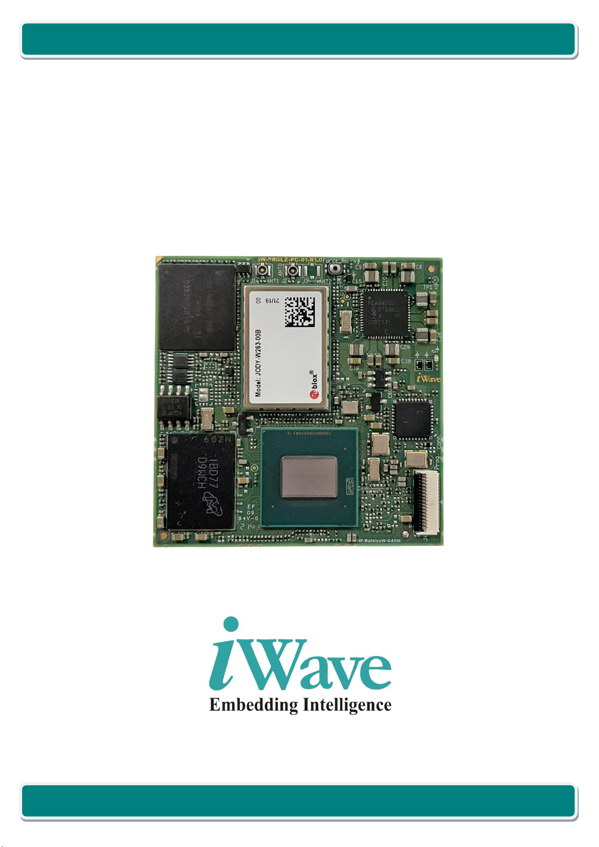
1.2 OSM LGA Module Overview .............................................................................................................................7
1.3 List of Acronyms................................................................................................................................................7
1.4 Terminology Description...................................................................................................................................9
1.5 References ........................................................................................................................................................9
1.6 Important Note ...............................................................................................................................................10
2. ARCHITECTURE AND DESIGN....................................................................................................................... 11
2.1 i.MX 8M Plus OSM LGA Module Block Diagram .............................................................................................11
2.2 i.MX 8M Plus SOM Features...........................................................................................................................12
2.3 i.MX 8M Plus SoC ............................................................................................................................................14
2.4 PCA9450C PMIC ..............................................................................................................................................15
2.5 Memory...........................................................................................................................................................15
2.5.1 LPDDR4 RAM...............................................................................................................................................15
2.5.2 eMMC Flash ................................................................................................................................................15
2.6 Network & Communiation..............................................................................................................................16
2.6.1 Wi-Fi and Bluetooth Interface.....................................................................................................................16
2.6.2 RTC Controller .............................................................................................................................................17
2.7 OSM BGA.........................................................................................................................................................18
2.7.1 RGMII Interface...........................................................................................................................................36
2.7.2 USB3.0 OTG Interface..................................................................................................................................38
2.7.3 USB3.0 Host Interface .................................................................................................................................39
2.7.4 USB 2.0 Host Interface ................................................................................................................................40
2.7.5 PCIe Interface ..............................................................................................................................................42
2.7.6 MIPI CSI Interface........................................................................................................................................43
2.7.7 HDMI TX Interface.......................................................................................................................................44
2.7.8 MIPI DSI/LVDS Display Interface .................................................................................................................45
2.7.9 Audio Interface............................................................................................................................................46
2.7.10 SPI Interface ................................................................................................................................................47
2.7.11 Data UART...................................................................................................................................................47
2.7.12 OSM GPIOs ..................................................................................................................................................48
2.7.13 CAN Interface ..............................................................................................................................................49
2.7.14 I2C Interface ................................................................................................................................................50
2.7.15 Control Signals ............................................................................................................................................50
2.7.16 Boot Select...................................................................................................................................................51
2.7.17 Power and GND...........................................................................................................................................51
2.8 Other Features................................................................................................................................................53
2.8.1 Programming Header..................................................................................................................................53
2.9 i.MX 8M Plus Pin Multiplexing on OSM BGA ..................................................................................................54
3. TECHNICAL SPECIFICATION.......................................................................................................................... 60

i.MX 8M Plus OSM LGA Module Hardware User Guide
iWave Systems Technologies Pvt. Ltd.
REL0.1
Page 5 of 68
3.1 Electrical Characteristics .................................................................................................................................60
3.1.1 Power Input Requirement ...........................................................................................................................60
3.1.2 Power Input Sequencing..............................................................................................................................61
3.1.3 Power Consumption ....................................................................................................................................62
3.2 Environmental Characteristics........................................................................................................................63
3.2.1 Environmental Specification........................................................................................................................63
3.2.2 Heat Sink/ Heat Spreader............................................................................................................................63
3.2.3 RoHS Compliance ........................................................................................................................................64
3.2.4 Electrostatic Discharge................................................................................................................................64
3.3 Mechanical Characteristics .............................................................................................................................65
3.3.1 i.MX 8M Plus OSM LGA Module Mechanical Dimensions...........................................................................65
4. ORDERING INFORMATION .......................................................................................................................... 66
5. APPENDIX................................................................................................................................................... 67
5.1 i.MX 8M Plus Development platform .............................................................................................................67

i.MX 8M Plus OSM LGA Module Hardware User Guide
iWave Systems Technologies Pvt. Ltd.
REL0.1
Page 6 of 68
List of Figures
FIGURE 1: I.MX 8M PLUS OSM LGA MODULE BLOCK DIAGRAM ................................................................................................................ 11
FIGURE 2: I.MX 8M PLUS BLOCK DIAGRAM ............................................................................................................................................... 14
FIGURE 3: WI-FI AND BLUETOOTH ANTENNA CONNECTOR ............................................................................................................................ 16
FIGURE 4: OSM LGA/BGA BALLS ........................................................................................................................................................... 18
FIGURE 5: POWER INPUT SEQUENCING ...................................................................................................................................................... 61
FIGURE 6: I.MX 8M PLUS OSM DEVELOPMENT PLATFORM.......................................................................................................................... 67
List of Tables
TABLE 1: ACRONYMS &ABBREVIATIONS ...................................................................................................................................................... 7
TABLE 2: TERMINOLOGY ........................................................................................................................................................................... 9
TABLE 3: OSM BGA PINOUTS ................................................................................................................................................................. 19
TABLE 4: PROGRAMMING HEADER PIN ASSIGNMENT .................................................................................................................................... 53
TABLE 6: I.MX 8M PLUS SOCIOMUX FOR OSM EDGE CONNECTOR INTERFACES ............................................................................................ 54
TABLE 7: POWER INPUT REQUIREMENT...................................................................................................................................................... 60
TABLE 8: POWER SEQUENCE TIMING......................................................................................................................................................... 61
TABLE 9: POWER CONSUMPTION.............................................................................................................................................................. 62
TABLE 10: ENVIRONMENTAL SPECIFICATION ............................................................................................................................................... 63
TABLE 11: ORDERABLE PRODUCT PART NUMBERS ....................................................................................................................................... 66

i.MX 8M Plus OSM LGA Module Hardware User Guide
iWave Systems Technologies Pvt. Ltd.
REL0.1
Page 7 of 68
1. INTRODUCTION
1.1 Purpose
This document is the Hardware User Guide for the NXP’s i.MX 8M Plus (Quad/QuadLite/Dual) Application processor
based OSM v1.0 specification compatible LGA module. This board is fully supported by iWave Systems Technologies
Pvt. Ltd. This Guide provides detailed information on the overall design and usage of the i.MX 8M Plus OSM Module
from a Hardware Systems perspective.
1.2 OSM LGA Module Overview
The OSM V1.0 (“Open Standard Modules™”) is a future proof and versatile standard for small size, low-cost embedded
computer modules. Combining the following key characteristics like Completely machine processible during soldering,
assembly and testing, Pre-tinned LGA package for direct PCB soldering without connector.
The OSM Module definition targeting application that requires low power, low costs, and high performance. The
Modules are used as building blocks for portable and stationary embedded systems. The core SoC and support circuits,
including DRAM, boot flash, power sequencing, SoC power supplies are concentrated on the Module. The Modules
are used with application specific Carrier Boards that implement other features such as audio CODECs, touch
controllers, wireless devices, etc. The modular approach allows scalability, fast time to market and upgradability while
still maintaining low costs, low power and small physical size.
NXP’s i.MX 8M Plus SoC based OSM LGA Module is rich with i.MX 8M Plus features along with on SOM LPDDR4, eMMC,
USB2.0 Hub, Wi-Fi & BT module and comes in compact 45mm x 45mm form factor (Size L). The Module PCB has 662
contacts which can be mounted as LGA/BGA on OSM carrier card.
1.3 List of Acronyms
The following acronyms will be used throughout this document.
Table 1: Acronyms & Abbreviations
Acronyms
Abbreviations
ARM
Advanced RISC Machine
BT
Bluetooth
CAN
Controller Area Network
CODEC
Coder-Decoder
CPU
Central Processing Unit
CSI
Camera Serial Interface
CTS
Clear to Send
DP
Display Port
DRAM
Dynamic Random Access Memory
DSI
Display Serial Interface

i.MX 8M Plus OSM LGA Module Hardware User Guide
iWave Systems Technologies Pvt. Ltd.
REL0.1
Page 8 of 68
Acronyms
Abbreviations
eMMC
Enhanced Multi Media Card
EMS
Electronics manufacturing services
ESAI
Enhanced Serial Audio Interface
FLEXCAN
Flexible Control Area Network
FlexSPI
Flexible Serial Peripheral Interface
GB
Giga Byte
Gbps
Gigabits per sec
GPIO
General Purpose Input Output
GPU
Graphics Processing Unit
HDCP
High-bandwidth Digital Content Protection
HDMI
High-Definition Multimedia Interface
I2C
Inter-Integrated Circuit
I2S
Inter-Integrated Sound
IC
Integrated Circuit
JTAG
Joint Test Action Group
LPDDR4
Low Power Double Data Rate4
MHz
Mega Hertz
MIPI
Mobile Industry Processor Interface
MLB
Media Local Bus
OSM
Open Standard Module
OTG
On-The-Go
PCB
Printed Circuit Board
PCIe
Peripheral Component Interconnect express
PMIC
Power management integrated circuits
RAM
Random Access Memory
RGMI
Reduced gigabit media-independent interface
RoHS
Restriction of Hazardous Substances
RTC
Real Time Clock
RTS
Request to Send
SAI
Serial Audio Interface
SATA
Serial Advanced Technology Attachment
SD
Secure Digital
SDIO
Secure Digital Input Output
SoC
System on Chip
SOM
System On Module
SPDIF
The Sony/Philips Digital Interface
SPI
Serial Peripheral Interface
UART
Universal Asynchronous Receiver/Transmitter
USB
Universal Serial Bus
VPU
Video Processing Unit
Wi-Fi
Wireless Fidelity

i.MX 8M Plus OSM LGA Module Hardware User Guide
iWave Systems Technologies Pvt. Ltd.
REL0.1
Page 9 of 68
1.4 Terminology Description
In this document, wherever Signal Type is mentioned, below terminology is used.
Table 2: Terminology
Terminology
Description
I
Input Signal
O
Output Signal
IO
Bidirectional Input/output Signal
CMOS
Complementary Metal Oxide Semiconductor Signal
HCSL
High speed Current Steering Logic
LVDS
Low Voltage Differential Signal
HDMI
High-Definition Multimedia Interface Differential Signal
DP
Display Port Differential Signal
GBE
Gigabit Ethernet Signal
PCIe
PCIe differential pair signals
SATA
Serial Advanced Technology Attachment differential pair signals
USB HS
Universal Serial Bus High Speed differential pair signals
USB SS
Universal Serial Bus Super Speed differential pair signals
MIPI
Mobile Industry Processor Interface differential pair signals
OD
Open Drain Signal
OC
Open Collector Signal
Power
Power Pin
PU
Pull Up
PD
Pull Down
NA
Not Applicable
NC
Not Connected
Note: Signal Type does not include internal pull-ups or pull-downs implemented by the chip vendors and only includes
the pull-ups or pull-downs implemented On-OSM SOM.
1.5 References
•IMX8MPXEC_Rev_x.pdf
•iMX_8M_Plus_RM_Revx.pdf
•OSM Specification V1.0

i.MX 8M Plus OSM LGA Module Hardware User Guide
iWave Systems Technologies Pvt. Ltd.
REL0.1
Page 10 of 68
1.6 Important Note
In this document, wherever i.MX 8M Plus SoC signal name is mentioned, it is followed as per below format for easy
understanding.
•If SoC pin doesn’t have multiplexing option or used for dedicated functionality then the signal name is
mentioned as functionality name.
“Functionality Name”
Example: ENET1_RGMII_TXC
In this signal, ENET1_RGMII_TXC pad is used for same functionality.
•If SoC pin selected as GPIO function, then the signal name is mentioned as
“Functionality Description (GPIO Number)”
Example: BCONFIG_0(GPIO1_05)
In this signal, BCONFIG_0 is the GPIO functionality and GPIO1_05 is the GPIO number.
Note: The above naming is not applicable for other signals which are not connected to SoC.

i.MX 8M Plus OSM LGA Module Hardware User Guide
iWave Systems Technologies Pvt. Ltd.
REL0.1
Page 11 of 68
2. ARCHITECTURE AND DESIGN
This section provides detailed information about i.MX 8M Plus OSM LGA Module SOM and Hardware architecture with
high level block diagram.
2.1 i.MX 8M Plus OSM LGA Module Block Diagram
‘
iWave Systems Technologies Pvt. Ltd.
i.MX 8M Plus
RGMII x 2
LPDDR4 (32bit)
LPDDR4-2GB
(Upgradable) ENET1,
ENET_QOS
USB2_3.0 USB3.0 x 1
DDRC
MMC (8bit)
eMMC –16GB
(Upgradable) uSDHC1
I2C
RTC Controller
USB2_2.0
uSDHC3
WiFi-BT
Module
UART1
PMIC
UART x 1
MIPI DSI x 1
SAI3
SAI
iW-RainboW-G40M-i.MX 8M Plus OSM Block Diagram
USB2.0
1:4 Hub
USB2.0 x 1
eCSPI1,
eCSPI2
MIPI_DSI
HDMI x 1
UART4 Debug UART x 1
I2C1
Boot mode
USB[0]
SD1 (4bit)
USB[2]
Wi-Fi
ANT Conn.
HDMI
USB[1]
SPI x 2
LVDS0,
LVDS1 LVDS0 x 2
JTAG JTAG x 1
OSM BGA
Balls
USB3.1 x 1
USB1_2.0,
USB1_3.0
USB[3]
PCIe PCIe x 1
uSDHC1 SDIO x 1
MIPI CSI0,
MIPI CSI1* MIPI CSI x 2
CAN1,
CAN2 CAN x 2
I2C2,
I2C3 I2C x 2
SAI5 I2S x 1
UART2,
UART3, UART x 2
GPIO GPIO x 16
uSDHC3
UART1
GPIO
uSDHC3
UART1
ANT_MAIN
ANT_MAIN
Power to
Peripherals 5V
On-Board
Regulators
PWM PWM x 4
Boot mode
WL_PCIe x 1
WL_PCIe x 1
BT
ANT Conn.
ANT_AUX
*Supported through Vendor Defined pins.
Figure 1: i.MX 8M Plus OSM LGA MODULE Block Diagram

i.MX 8M Plus OSM LGA Module Hardware User Guide
iWave Systems Technologies Pvt. Ltd.
REL0.1
Page 12 of 68
2.2 i.MX 8M Plus SOM Features
i.MX 8M Plus OSM LGA Module supports the following features.
SoC
•i.MX 8M Plus Applications Processor
oi.MX 8M Plus Quad : 4 x Cortex-A53, 1 x Cortex-M7, GPU, VPU, NPU, ISP & HiFi4 Audio DSP
oi.MX 8M Plus QuadLite : 4 x Cortex-A53, 1 x Cortex-M7 & GPU
oi.MX 8M Plus Dual : 2 x Cortex-A53, 1 x Cortex-M7, GPU, VPU, NPU, ISP & HiFi4 Audio DSP
Power
•PCA9450C PMIC
Memory
•LPDDR4 - 2GB (Expandable up to 8GB)1,2
•eMMC Flash - 16GB (Expandable up to 128GB)2
Other On-SOM Features
•IEEE 802.11 a/b/g/n/ac/ax Wi-Fi & BT 5.0 (ax is optional)
•USB 2.0 High Speed 4-Port Hub
•RTC Controller
•Programming Header
OSM LGA Interfaces
•RGMII x 2
•SDIO x 2 (4-bit x 1, 8-bit x 1)3
•USB 3.0 x 2
•USB 2.0 x 2
•PCIe 3.0 x 1 Ports
•HDMI 2.0 Transmitter x 1 Port
•MIPI DSI 4 lane x 1
•LVDS x 2 Channel
•SAI/I2S (Audio Interface) x 1 Port
•SPI x 2 Port
•Data UART (with CTS & RTS) x 1 Port6
•Data UART (without CTS & RTS) x 2 Port (One port can be used as Debug Port)4
•OSM GPIOs
•CAN FD x 2 Port
•I2C x 2 Ports

i.MX 8M Plus OSM LGA Module Hardware User Guide
iWave Systems Technologies Pvt. Ltd.
REL0.1
Page 13 of 68
General Specification
•Power Supply : 5V, 2.5A
•Form Factor : 45mm X 45mm (OSM V1.0 Specification)
1. The i.MX 8M Plus supports upto 4GB of RAM. It can support 8GB RAM (32-bit)if LPDDR4 chip is available.
2. Memory Size will differ based on iWave’s SOM Product Part Number.
3. In default configuration, If on SOM Wi-Fi module is used, SD1 will not be supported on OSM BALL.

i.MX 8M Plus OSM LGA Module Hardware User Guide
iWave Systems Technologies Pvt. Ltd.
REL0.1
Page 14 of 68
2.3 i.MX 8M Plus SoC
iW-RainboW-G40M OSM LGA Module can support i.MX 8M Plus SoCs from NXP. The i.MX 8M Plus Family consists of
three processors: i.MX 8M Plus Quad, I.MX 8M Plus QuadLite & i.MX 8M Plus Dual. The Major Difference between
i.MX 8M Plus SoCs are:
•i.MX 8M Plus Quad : 4 x Cortex-A53, 1 x Cortex-M7, GPU, VPU, NPU, ISP & HiFi4 Audio DSP
•i.MX 8M Plus QuadLite : 4 x Cortex-A53, 1 x Cortex-M7 & GPU
•i.MX 8M Plus Dual : 2 x Cortex-A53, 1 x Cortex-M7, GPU, VPU, NPU, ISP & HiFi4 Audio DSP
The i.MX 8M Plus processors along with ARM core supports integrated NPU of 2.3 TOPs, OpenCL GPU, Image Signal
Processor, 1080p60 video encode and decode capable VPU, 3 x display controllers, multiple display output options,
including MIPI-DSI, HDMI 2.0, and LVDS. Memory interfaces supporting LPDDR4, Quad SPI/Octal SPI (FlexSPI), eMMC
5.1, SD 3.0 and a wide range of peripheral I/Os such as PCIe 3.0 provide wide flexibility.
Figure 2: i.MX 8M Plus Block Diagram
Note: The i.MX 8M Plus processor offers numerous advanced features, please refer the latest i.MX 8M Plus Datasheet
& Reference Manual for Electrical characteristics and other information, which may be revised from time to time.

i.MX 8M Plus OSM LGA Module Hardware User Guide
iWave Systems Technologies Pvt. Ltd.
REL0.1
Page 15 of 68
2.4 PCA9450C PMIC
The i.MX 8M Plus OSM LGA Module uses one PCA9450C PMIC (U3) for module power management. The PCA9450C
features six high efficiency step-down regulators and five linear regulators. It is a high-performance power
management integrated circuit (PMIC) that provides a highly programmable/configurable architecture with fully
integrated power devices and built-in one-time programmable memory stores key start up configurations, drastically
reducing external components typically used to set output voltage and sequence of external regulators. Regulator
parameters are adjustable through high-speed I2C after start up offering flexibility for different system states. The
PCA9450C PMIC comes in 56pin 7x7 QFN Package and is placed on the Top side of the SOM.
2.5 Memory
2.5.1 LPDDR4 RAM
The i.MX 8M Plus OSM LGA Module supports 2GB LPDDR4 RAM memory by default using 32bit DDR_CH0 channel of
i.MX 8M Plus SoC to support LPDDR4 up to 2GHz. LPDDR4 part U12 is placed on Top side of the SOM. The RAM size
can be expandable up to maximum of 8GB (if chips are available). To customize the LPDDR4 memory size, contact
iWave.
2.5.2 eMMC Flash
The i.MX 8M Plus OSM LGA Module supports 16GB eMMC as default boot and storage device. This is directly
connected to uSDHC3 controller of the i.MX 8M Plus SoC and operates at 1.8V (I/O supply) and 3.3V (NAND core
supply) Voltage levels.
The eMMC flash memory (U2) is physically located on bottom side of the LGA Module. The memory size of the eMMC
Flash can be customised based on the requirement by contacting iWave Support Team.

i.MX 8M Plus OSM LGA Module Hardware User Guide
iWave Systems Technologies Pvt. Ltd.
REL0.1
Page 16 of 68
2.6 Network & Communiation
2.6.1 Wi-Fi and Bluetooth Interface
The i.MX 8M Plus OSM LGA Module is integrated with u-blox’s “JODY-W263” or “JODY-W374” based Wi-Fi & Bluetooth
module. The JODY-W2/W3 series are compact modules based on the Marvell 88W8987 AEC-Q100 compliant chipset.
They enable Wi-Fi, Bluetooth, and Bluetooth low energy communication. The JODY-W2 modules can be operated in
the following modes:
• Wi-Fi 1x1 802.11a/b/g/n/ac in 2.4 GHz or 5 GHz
• Dual-mode Bluetooth 5, including audio, can be operated fully simultaneous with Wi-Fi
The JODY-W3 modules can be operated in the following modes:
• Wi-Fi6 802.11a/b/g/n/ac/ax in 2.4 GHz or 5 GHz
• Bluetooth/Bluetooth LE 5.1 including audio, can be operated fully simultaneous with Wi-Fi
The JODY-W2 undergoes extended automotive qualification according to ISO 16750-4 and is manufactured in line with
ISO/TS 16949. Connection to a host processor is through SDIO, or High-Speed UART interfaces. The i.MX 8M Plus
Module uses processor’s UART1 interface for Bluetooth and USDHC1 interface for Wi-Fi in a default configuration. In
the OSM module, antenna pins of JODY-W2/W3 Bluetooth and Wi-Fi are connected to J1, J2 and J3 connectors.
Figure 3: Wi-Fi and Bluetooth Antenna Connector
Connector Part Number - : RECE-20449-001E-01 from Taoglas Limited / MM4829-2702RA4 from Murata.
Antenna Part Number - : FXP830.24.0100B from Taoglas Limited / 2042811100 from Molex
Note: Contact iWave support team if JODY-W3 Support is required.

i.MX 8M Plus OSM LGA Module Hardware User Guide
iWave Systems Technologies Pvt. Ltd.
REL0.1
Page 17 of 68
2.6.2 RTC Controller
The i.MX 8M Plus OSM LGA Module by supports external RTC Controller “PCF85263” On-SOM for Real time clock
support. This external RTC Controller is connected to i.MX 8M Plus SoC through I2C3 Interface and operates at 3.3V
voltage level. In SOM power off condition, this device will take power from OSM ball #W17 (VRTC_3V0) coin cell power
and continues to keep the current time.

i.MX 8M Plus OSM LGA Module Hardware User Guide
iWave Systems Technologies Pvt. Ltd.
REL0.1
Page 18 of 68
2.7 OSM LGA/BGA Balls
OSM LGA/BGA Balls has standard pinout as per OSM Specification V1.0 The interfaces which are available at 662
contacts are explained in the following sections.
Figure 4: OSM LGA/BGA Balls
Number of contacts - : 662

i.MX 8M Plus OSM LGA Module Hardware User Guide
iWave Systems Technologies Pvt. Ltd.
REL0.1
Page 19 of 68
Table 3: OSM Pinouts
OSM Pins
Signal
SIZE 0
M18
NC
N18
NC
U19
BOOT_SEL#
AB17
FLEXCAN1_RX(SAI5_RXD2)
AC17
FLEXCAN1_TX(SAI5_RXD1)
AB19
FLEXCAN2_RX(SAI5_MCLK)
AC19
FLEXCAN2_TX(SAI5_RXD3)
V17
CARRIER_PWR_ON
A15
GND
A16
OSM_ANT0
A17
GND
A18
GND
A19
GND
A20
OSM_ANT1
A21
GND
B15
GND
B16
GND
B17
GND
B18
GND
B19
GND
B20
GND
B21
GND
C15
NC
C17
NC
C19
NC
C21
NC
AC18
JTAG_MOD
F15
NC
E16
NC
R15
ENET_QOS_RGMII_RXC
M15
ENET_QOS_RGMII_RX_CTL
L16
NC
N15
ENET_QOS_RGMII_RD2
P15
ENET_QOS_RGMII_RD3
J15
ENET_QOS_RGMII_TXC
K16
ENET_QOS_RGMII_TX_CTL
H16
ENET_QOS_RGMII_TD2
G16
ENET_QOS_RGMII_TD3
K15
ENET_QOS_RGMII_RD0

i.MX 8M Plus OSM LGA Module Hardware User Guide
iWave Systems Technologies Pvt. Ltd.
REL0.1
Page 20 of 68
OSM Pins
Signal
L15
ENET_QOS_RGMII_RD1
H15
ENET_QOS_RGMII_TD0
G15
ENET_QOS_RGMII_TD1
N16
NC
T16
ENET_QOS_MDC
T15
ENET_QOS_MDIO
D18
GND
E15
GND
E21
GND
F16
GND
F20
GND
J16
GND
J20
GND
L18
GND
M16
GND
M20
GND
P18
GND
R16
GND
R20
GND
V16
GND
V20
GND
Y18
GND
AA14
GND
AA17
GND
AA19
GND
AA22
GND
AB15
GND
AB21
GND
D17
OSM_GPIO_A_0(SAI1_TXD6_GPIO4_18)
E17
OSM_GPIO_A_1(SAI1_TXD7_GPIO4_19)
F17
OSM_GPIO_A_2(SAI1_RXFS_GPIO4_0)
G17
OSM_GPIO_A_3(SAI1_RXC_GPIO4_1)
H17
OSM_GPIO_A_4(SAI1_RXD0_GPIO4_2)
J17
OSM_GPIO_A_5(SAI5_RXC_GPIO3_20)
K17
OSM_GPIO_A_6(SAI2_RXC_GPIO4_22)
L17
OSM_GPIO_A_7(SAI2_RXFS_GPIO4_21)
D19
OSM_GPIO_B_0(SAI3_RXFS_GPIO4_28)
E19
OSM_GPIO_B_1(SAI1_RXD1_GPIO4_3)
F19
OSM_GPIO_B_2(SAI5_RXFS_GPIO3_21)
G19
OSM_GPIO_B_3(SPDIF1_EXT_CLK_GPIO5_5)
H19
OSM_GPIO_B_4(NAND_DQS_GPIO3_21)
Table of contents
Popular Control Unit manuals by other brands

Danfoss
Danfoss PVG 128 installation guide

Distech Controls
Distech Controls SOLSTYCE Series installation guide

Harvia
Harvia XENIO COMBI CX30C-U1 Instructions for installation and use

Aventics
Aventics ED07 operating instructions

Woodward
Woodward easYlite-200 manual

resideo
resideo V8200 installation instructions

Haier
Haier GE WE04X27596 Part Install Instructions

Espressif
Espressif ESP32--MINI--1 user manual

VBK technology
VBK technology Uniquom manual

Mitsubishi Electric
Mitsubishi Electric MN Converter installation manual

Advanced Micro Controls Inc.
Advanced Micro Controls Inc. 1700 Series user manual

Bosch
Bosch rexroth 4WS2EM10 5X XH Series operating instructions