ixtur MAP-6 Instruction sheet

22.01.2019
IXTUR OY | VARESPELLONTIE 6, FI-21500 KAARINA FINLAND, WWW.IXTUR.COM
Product Instructions
PNEUMATIC MAGNET IXTUR MAP-6
Original User Manual

Ixtur Ltd / MAP-6
1
Content
Introduction and Warnings ............................................................................................................................ 2
Technical Specifications ................................................................................................................................ 3
Holding Force .................................................................................................................................................. 4
Installing the Product ...................................................................................................................................... 6
Using MAP-6 pneumatic magnet .................................................................................................................. 8
Maintenance and inspections ....................................................................................................................... 8
Warranty ........................................................................................................................................................... 8
Patent Pending ................................................................................................................................................ 8
Declaration of Conformity .............................................................................................................................. 9

Ixtur Ltd / MAP-6
2
Introduction and Warnings
MAP-6 is a pneumatic magnet meant for attaching ferromagnetic parts in lifting, work holding or
automation applications. The magnet’s state, attached or detached, can be changed pneumatical-
ly. MAP-6 pneumatic magnet doesn’t need compressed air to keep its state. Air pressure is needed
only to change the state from attached to detached or vice versa.
•Please read this manual carefully before deployment to ensure safe use of the device.
•This device includes a source of magnetic field. A fluctuating magnetic field is produced
during the use in the proximity of the device.
•This device produces a magnetic field that may interfere with medical devices such as
metallic implants or cardiac pacemakers. Do not use this device and keep out of close
proximity unless you have approval from the manufacturer of the medical device or from
your physician.
•Do not disassemble or replace the device parts. Only pneumatic connectors are user
changeable.
•The device must not be used for lifting or transporting people.
•Always pay special attention to the factors that may decrease the holding force of the
magnet.
•The permitted holding force must not be exceeded.
•Do not operate a damaged or malfunctioning device.
•The designer and manufacturer of other systems should always ensure that systems where
this device will be integrated to meet local and national safety regulations.

Ixtur Ltd / MAP-6
3
Technical Specifications
Dimensions:
-Height: 35.0 mm
-Diameter: 35.0 mm
-Weight: 0.19 kg
Capacity:
-Holding force: minimum 177 N (S235 S ≥4 mm)
-Rated lifting capacity with safety factor 3: 6.0 kg (S235 S ≥4 mm)
-Residual holding force: maximum 0.3 N
Environmental conditions:
-Operating temperature: 0 °C … +50 °C
-Storage temperature: -20 °C … +50 °C
-Humidity: 0 % … 90 %
-IP67 (The product is protected from dust and temporary immersion up to 1 m)
Requirements for compressed air:
-Recommended pressure: 6.0 bar
-Functional range: 5.0 … 8.0 bar
-Water separating
-Particle filtering 5µm
Information related to medical implants
-Safety distance for a person with active implanted device is 50 cm of air or other non-
magnetic material. The distance is measured from the magnet or magnetic material
attached to it.
oMaximum static magnetic field of MAP-6 is 200 mT on the gripping surface.
oInterference with active implanted devices, e.g. cardiac pacemakers – Action level for expo-
sure to static magnetic fields is 0,5 mT [Directive 2013/35/EC].

Ixtur Ltd / MAP-6
4
Holding Force
Holding force and rated lifting capacity of MAP-6 can only be applied when the forces are perpen-
dicular to the magnet's gripping surface.
Three factors affect magnet’s holding force:
-Material properties
-Thickness of the load
-Distance between gripping surface and attached load (airgap)
Holding force and lifting capacity of MAP-6 pneumatic magnet are rated with steel EN S235. Most
other steel materials produce lower holding force. Also hardened steel produces lower holding
force.
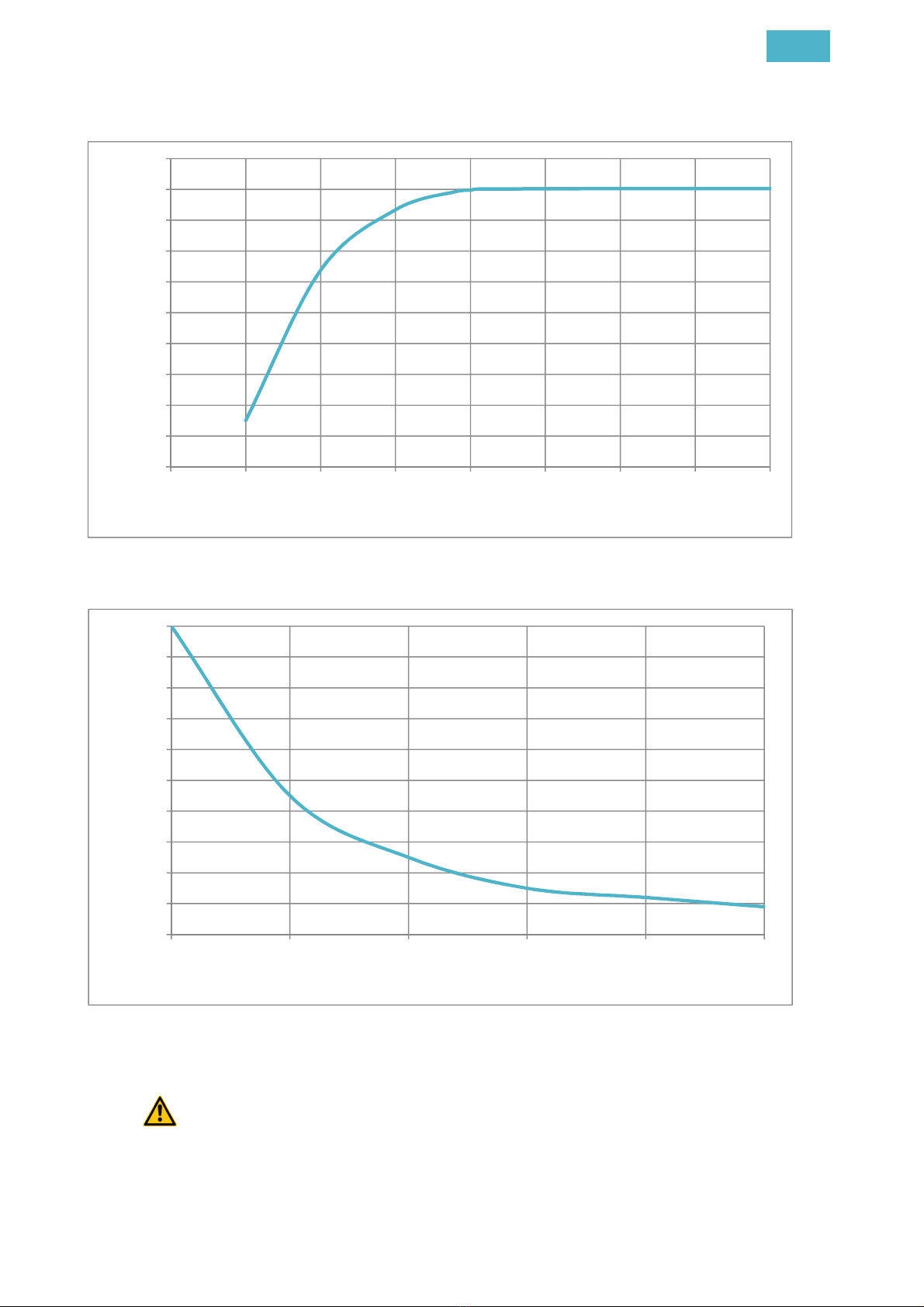
Material’s capacity to conduct magnetic field depends on its thickness. A thinner material has
weaker capacity compared to a thicker material. Increasing material thickness increases the mate-
rial’s capability to conduct magnetic field until a magnet specific maximum value is reached. See
figure 2: MAP-6 holding force in proportion to material thickness
Any material that separates the magnet's gripping surface from the surface of the load reduces the
total magnetic holding force. Reduction can be caused by non-magnetic materials or by materials
with weak magnetic qualities, such as, zinc or paint or similar coating, rust, frost or air. The dis-
tance between the surfaces caused by materials above is commonly called as airgap.
Surfaces must be clean and the airgap zero to achieve maximum holding force. The load surface
must also be flat and it must occupy the gripping surface of the device completely. See figure 3:
MAP-6 holding force in proportion to airgap.
Figure 1. The gripping surface and magnetic poles of MAP-6.

Ixtur Ltd / MAP-6
5
Figure 2. MAP-6 holding force in proportion to material thickness
Figure 3. MAP-6 holding force in proportion to airgap
Holding force of 177 N is determined with steel EN S235 with material thickness 4.0
mm. Most other magnetic materials result in lower holding force.
0
20
40
60
80
100
120
140
160
180
200
012345678
Holding force [N]
Material thickness [mm]
0
10
20
30
40
50
60
70
80
90
100
0 0,1 0,2 0,3 0,4 0,5
Holding force %
Airgap [mm]

Ixtur Ltd / MAP-6
6
When lifting a piece from a stack, note that also the piece below the lifted piece can be
attached to the magnet.
The forces caused by acceleration must be considered. For example, sudden moves
cause stronger forces than slow and smooth moves.
Before magnet attachment, both the magnet's gripping surface and the load material
surface must be cleaned of foreign materials to minimize the airgap that reduces the hold-
ing force.
Due to residual magnetism, the magnet's lifting surface may contain minor magnetic
particles or pieces which reduce the holding force.
The load material surface may bend, which produces an airgap and reduces the hold-
ing force. Especially thin materials may cause this effect.
Installing the Product
MAP-6 pneumatic magnet has to be installed using an M5 screw according to Figure 6. The pneu-
matic connections have to be made using 4.0 mm hose.
Figure 4. Mounting dimensions of MAP-6

Ixtur Ltd / MAP-6
7
Figure 5. Recommended mounting dimensions in adapter
Figure 6. Mounting dimensions of MAP-6. Top view.

Ixtur Ltd / MAP-6
8
Using MAP-6 pneumatic magnet
When the air pressure in the upper pneumatic connection is at least 5.0 bar higher than in the low-
er connection, the magnet is set ON (attach the metal). When the air pressure in the lower pneu-
matic connection is at least 5.0 bar higher than in the upper connection, the magnet is set OFF
(detach the metal). The same pressure in both air hose contacts or no pressure at all keeps the
magnet’s current state.
Maintenance and inspections
MAP-6 pneumatic magnet itself is maintenance free.
If MAP-6 pneumatic magnet has been dropped down or it has been exposed to some other impact,
it must be inspected for any damages before continuing its use.
Do not use the device if you find any damages or malfunctions!
Warranty
The product has a 12 months warranty from the date of delivery. The warranty covers material and
manufacturing defects. Warranty does not cover defects caused by a misuse of the product against
the instructions and regulations in this manual. The warranty does not cover normal wear and tear.
Patent Pending
Several patent applications are pending related to MAP-6 and Ixtur pneumatic magnet technology.

Ixtur Ltd / MAP-6
9
Declaration of Conformity
Declaration of incorporation of partly completed machinery
Directive 2006/42/EC
We hereby declare that this partly completed machinery, Pneumatic Magnet MAP-6, complies with
the essential requirements of the Directive 2006/42/EC on Machinery and the following harmonized
standards have been applied and fulfilled:
-EN ISO 12100:2010
-ISO/TR 14121-2:2007
-EN 13155:2003+A2:2009
The technical documents of partly completed machinery is compiled in accordance with section B
of Annex VII of Directive 2006/42/EC, that can be transmit, in response to a reasoned request by
the national authorities.
Partly completed machinery must not be put into service until the final machinery into which it is to
be incorporated has been declared in conformity with the provisions of the Directive 2006/42/CE on
Machinery.

22.01.2019
DECLARATION
OF INCORPORATION OF PARTLY COMPLETED MACHINERY
Trans ation of the origina
Directive 2006/42/EC
Ixtur Oy
Ixtur OyIxtur Oy
Ixtur Oy
Varespe ontie 6
21500 KAARINA
Fin and
Hereby dec ares that the fo owing part y comp eted machinery
Description
DescriptionDescription
Description Pneumatic magnet Gripper
Mode
ModeMode
Mode MAP-6
ID number
ID numberID number
ID number 815B … 099B
fu fi s the fo owing essentia requirements of Directive 2006/42/EY:
•Annex I: 1.1.2 a, 1.1.3, 1.1.5, 1.3.2, 1.3.4, 1.5.10
The technica documents of part y comp eted machinery is compi ed in accordance with section B of Annex VII of the
Directive 2006/42/EC.
The fo owing harmonized standards have been app ied:
•EN 13155:2003+A2:2009
•EN ISO 12100:2010
•ISO/TR 14121-2:2007
A re evant information about the part y comp eted machinery wi be transmitted by post or e ectronica y, in re-
sponse to a reasoned request by the nationa authorities.
Part y comp eted machinery must not be put into service unti the fina machinery into which it is to be incorporated
has been dec ared in conformity with the provisions of the Directive 2006/42/CE.
Person authorized to compi e the technica documentation:
Juho Suominen, Address: Varespe ontie 6, FI-21500 Kaarina, Fin and
The origina document of this dec aration is pub ished in Finnish Jan 22
nd
2019
P ace and date: Kaarina Jan 22
nd
2019
Markku Oksanen
Managing Director
Ixtur Oy
Table of contents
Other ixtur Industrial Equipment manuals

ixtur
ixtur MRP-100NK User manual

ixtur
ixtur MRP-42K User manual

ixtur
ixtur MRP-130F User manual

ixtur
ixtur MAP-40 Instruction sheet

ixtur
ixtur MRP-45 User manual

ixtur
ixtur MRP-31F User manual

ixtur
ixtur MRP-28NK User manual

ixtur
ixtur MRP-20NK User manual

ixtur
ixtur MRP-30F User manual

ixtur
ixtur MRP-31FK User manual
Popular Industrial Equipment manuals by other brands

Shimano
Shimano SG-8C20 Service manual

Magikist
Magikist MagikMinder MM100 operating manual

XpressFill
XpressFill XF4400 manual

ABB
ABB XAC23983 Operation manual

Schroeder America
Schroeder America 675-0153 Installation instruction, parts list and configuration guide

Bomar
Bomar Workline Series operating instructions