J-Power Nano Warbirds P-47 User instructions

Assembly and Operating Manual
Specification:
*Length:19‐1/10"(485mm)
*WingSpan:21‐7/10"(550mm)
*FlyingWeight:6oz(175g)
NanoWarbirds
P‐47

Assembly and Operating Manual Nano warbirds p-47
2
Dear customer,
Congratulations on your choice of a
factory-assembled model aircraft from the jpower
Nano warbirds range and thank you for placing
your trust in us.
The model can very quickly be completed ready to
fly. Please read right through these instructions
and the separate information sheets before
attempting to assemble and fly the model, as this
will make it much easier to complete the tasks
required.
All directions, such as “right-hand”, are as seen
from the tail of the model, looking forward.
Notes on the power system
Abrushless outrunner motor, propeller and spinner
are factory-installed.
The motor is connected to the speed controller,
ready to use, and the controller is correctly set up
at the factory.
To complete the power system all you have to do
is connect the LiPo flight battery.
The radio control system
For this model you require a radio control system
with at least four channels. We particularly
recommend 2.4 GHz systems.
The receiving system is powered by the speed
controller’s integral BEC system.
Before you check the model’s working systems,
set the control surfaces to neutral from the
transmitter (transmitter sticks and trims central).
Before operating the model always move the
throttle stick to the “motor stopped” position before
switching the transmitter on. Only then connect the
flight battery.
To switch off, first disconnect the flight pack from
the speed controller, and only then switch the
transmitter off.
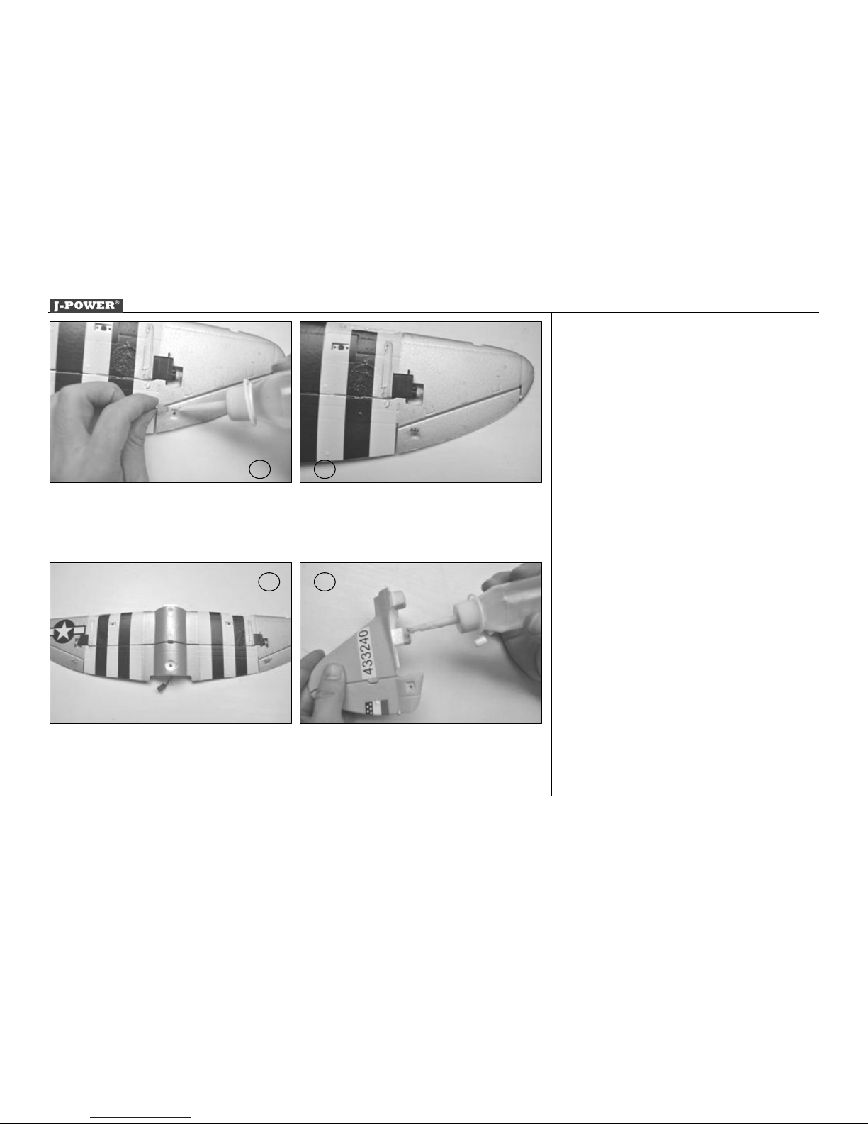
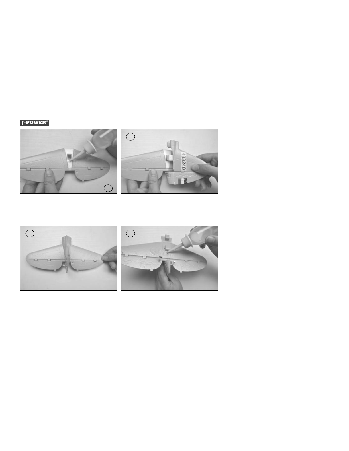
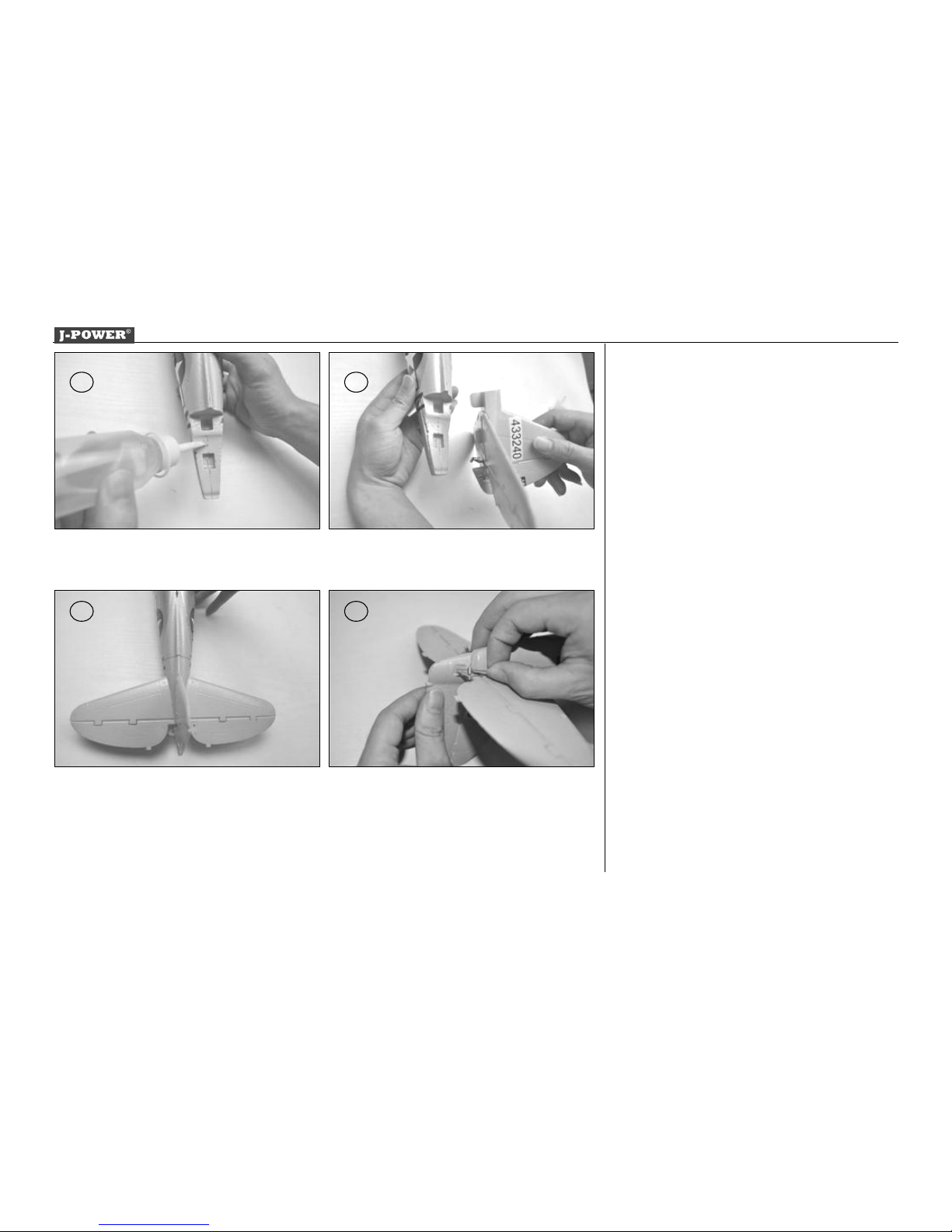
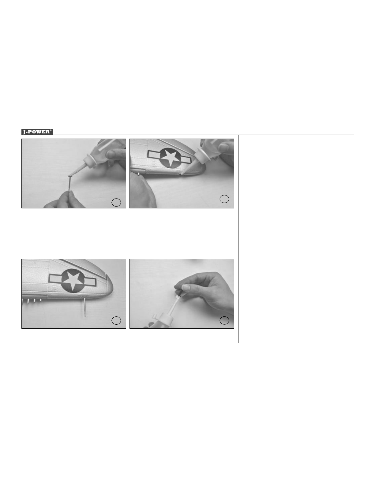
Glued joints, suitable adhesives
Foam safe epoxy is recommended and available
from most reputable model retail shops.
Trial-fit all parts “dry” before applying glue.
Follow the recommended curing time suggested
by the glue manufacturer. Allow the glue to fully
cure (harden) to the point where the joint can be
placed under stress.
Kit contents
Fuselage, complete with motor, speed controller
and servo.
Integral wing panels with L.H / R.H. ailerons and
servos
Tail plane and elevator
Fin
Factory-fitted propeller and spinner
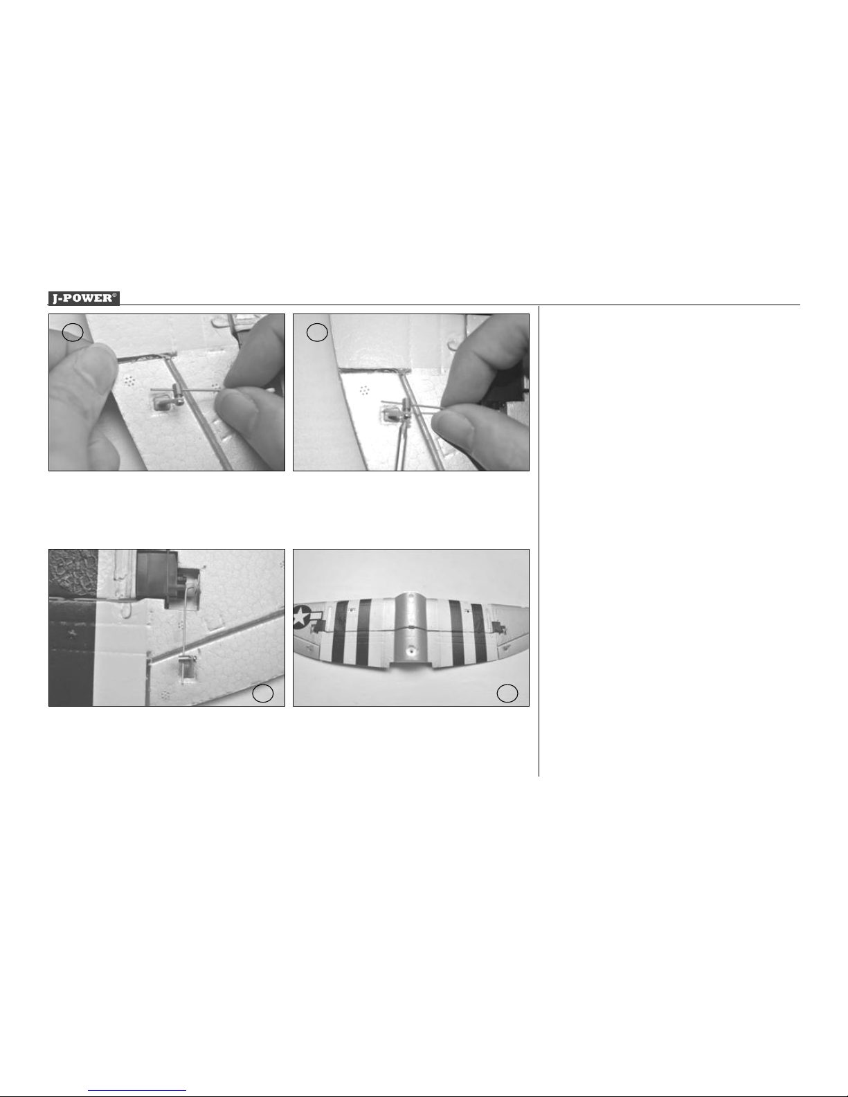
2 X Aileron pushrod, one Z-bend
1 X Elevator pushrod, one Z-bend.
1 X Vertical pushrod, one Z-bend.
4 X Control surface horn
1 X 2S1P LiPo battery,450 mAh, 25C

Assembly and Operating Manual Nano warbirds p-47
3
Fig. 1
- Glue the control rod to Horizontal tail. (glue not
included)
Fig. 2
- Remove any excess glue and hold in position until
glue sets. The photo shows the finished view.
Fig. 3
- Glue the control rod to vertical tail. (glue not
included)
Fig. 4
- Remove any excess glue and hold in position until
glue sets. The photo shows the finished view.
1 2
3 4

Assembly and Operating Manual Nano warbirds p-47
4
Fig. 5
- Glue the control rod to wing set. (glue not included)
Fig. 6
- Remove any excess glue and hold in position until
glue sets. The photo shows the finished view.
Fig. 7
- Reverse the procedure to the left side. The photo
shows the finished view.
Fig. 8
- Apply glue to the vertical tail (glue not included)
5
7 8
6

Assembly and Operating Manual Nano warbirds p-47
5
Fig. 9
- Apply glue to the horizon tail (glue not included)
Fig. 10
- Remove any excess glue and hold in position until
glue sets.
Figs. 11
- Photo shows the finished view.
Figs. 12
- Apply glue to the horizon tai (glue not included)
9
10
11 12

Assembly and Operating Manual Nano warbirds p-47
6
Figs. 13
- Apply glue to the fuselage (glue not included)
Figs. 14
- Assemble the horizon tail and vertical tail to
fuselage
Figs. 15
- Photo shows the finished view.
Figs. 16
- Connect the control rod to the vertical tail.
14
15 16
13

Assembly and Operating Manual Nano warbirds p-47
7
Figs. 17
- Tighten the control rod with screw.
Figs. 18
- Connect the control rod to the horizon tail.
Figs. 19
- Tighten the control rod with screw.
Figs. 20
- Connect the wing panel push rod to the servo arm
at third hole.
17
20
19
18

Assembly and Operating Manual Nano warbirds p-47
8
Figs. 21
- Assemble the elevator push rod to the wing set.
Figs. 22
- Tighten the elevator push rod with screw.
Figs. 23
- The photo shows the finished view.
Figs. 24
- Reverse the procedure to the left wing. The photo
shows the finished view.
21 22
23 24

Assembly and Operating Manual Nano warbirds p-47
9
Figs. 25
- Apply glue to the scatter-gun.
Figs. 26
- Apply glue to the wing panel.
Figs. 27
- Assemble the scatter-gun to the wing panel ,photo
shows the finished view.
Figs. 28
- Reverse the procedure to the left wing. The photo
shows the finished view.
25 26
27 28

Assembly and Operating Manual Nano warbirds p-47
10
Figs. 29
- Apply glue to the single scatter-gun.
Figs. 30
- Apply glue to the wing panel.
Figs. 31
- Assemble the single scatter-gun to the wing panel,
photo shows the finished view.
Figs. 32
- Apply glue to the antenna.
29 30
31 32

Assembly and Operating Manual Nano warbirds p-47
11
Figs. 33
- Assemble the antenna to the fuselage.
Figs. 34
- Photo shows the finished view.
Figs. 35
- Apply glue to the radiator.
Figs. 36
- Assemble the radiator to fuselage.
3635
3433

Assembly and Operating Manual Nano warbirds p-47
12
Figs. 37
- Photo shows the finished view.
Figs. 38
- Reverse the procedure to the right side. The photo
shows the finished view.
Figs. 39
- Assemble the main wing to the fuselage. Photo
shows the finished view .
Figs. 40
- Tighten the fixup presser.
38
39 40
37

Assembly and Operating Manual Nano warbirds p-47
13
Figs. 41
- Apply glue to the fuel tank.
Figs. 42
- Apply glue to fuselage.
Figs. 43
- Assemble the fuel tank to fuselage ,photo shows
the finished view.
Figs. 44
- Apply glue to missile
41
43
42
44

Assembly and Operating Manual Nano warbirds p-47
14
Figs. 45
- Apply glue to wing set.
Figs. 46
- Assemble the missile to wing set ,photo shows the
finished view .
Figs. 47
- Reverse the procedure to the right side. The photo
shows the finished view.
Figs. 48
45
47 48
46

Assembly and Operating Manual Nano warbirds p-47
15
- Fix the main landing gear with screw.
Figs. 49
- Photo shows the finished view.
Figs. 50
- Reverse the procedure to the left side. The photo
shows the finished view.
Figs. 51
- Photo shows the finished view.
Figs.52
- Apply A little glue to the nose cone.
52
51
5049

Assembly and Operating Manual Nano warbirds p-47
16
Figs. 53
- Apply glue to the fuselage.
Figs. 54
- Assemble the nose cone to fuselage, photo shows
the finished view.
Figs. 55
-Assemble the propeller to motor.
Figs. 56
- Fix the propeller with screw.
55 56
53 54

Assembly and Operating Manual Nano warbirds p-47
17
Figs. 57
- Connect to the receiver and place the receiver in
the middle of the fuselage.
Figs. 58
- Photo shows battery leads connected to the speed
controller.
Figs. 59
- Place the flight battery in the fuselage.
Figs. 60
- Opening and closing the canopy:
The canopy is retained by the cowl at the front,
and by a tongue at the rear
- To open the canopy, slide it forward, raise it at
the rear and lift it off
57 58
59
60
59

Assembly and Operating Manual Nano warbirds p-47
18
- Reverse the procedure to replace the canopy.
Figs. 61
- Place the battery in the model of balancing; do not
connect it.
- Make the Centre of Gravity on both sides.
- Support the model at the marked C.G. and allow it
to hang freely. The model is correctly balanced
when it hangs level, ideally with the nose inclined
slightly down.
- Adjust the position of the flight battery if necessary.
- Mark the battery location in the fuselage, so that
you can be confident of replacing it in the same
position after removing it.
Figs. 62
- Photo shows the balancing weight.
Fig. 63
- Charge the flight battery; connect the Equalizer
lead using and adapter lead matching your charger
(adapter lead not included).
61 62
63
62

Assembly and Operating Manual Nano warbirds p-47
19
Fig. 64
- Switch the transmitter on, and move the throttle
stick to the “Motor OFF” position. (Diagram MODE
1 right throttle control stick)
-
Fig. 65and 66
- Check the channel assignment of the control
surfaces, and swap over the connectors at the
- Check the neutral position of the control surfaces.
Make adjustments to the clevises if necessary.
- Stand behind the model.
- Check the direction of rotation of the servos.
- When you move the aileron stick to the right (a),
the right-hand aileron (a) should rise, the left-hand
aileron (b) fall.
- Pull the elevator stick back towards you (c), and
the rear edge of both elevators should rise (c).
- If either control surface function works the wrong
way round, correct it using your transmitter’s servo
reverse facility for that function.
- Check that all the linkages are firmly fixed, but
free-moving.
We recommend that you set around 50% Expo on
64
65 66

Assembly and Operating Manual Nano warbirds p-47
20
the aileron and elevator functions
Fig. 67 checking the electric power system
- Caution: position the throttle stick in such a way
that the motor cannot possibly start running
69
67
Table of contents
Other J-Power Toy manuals

J-Power
J-Power Explorer Prop User instructions

J-Power
J-Power P38 User manual

J-Power
J-Power P51 User manual

J-Power
J-Power A-7 User manual

J-Power
J-Power AJO THUNDERBOLT User manual

J-Power
J-Power Nano Warbirds T-28 User instructions

J-Power
J-Power F5E Tiger 2 User manual

J-Power
J-Power Grob 120TP User instructions

J-Power
J-Power KATANA User instructions

J-Power
J-Power SKY SURFER User manual
Popular Toy manuals by other brands

Bontempi
Bontempi 10 2010 owner's manual

Volantex
Volantex VECTOR SRG5 user manual

ROBBE
ROBBE LIMIT PRO Instruction and user's manual

DERBEE
DERBEE F4U CORSAIR manual

The World Models Manufacturing
The World Models Manufacturing MIDGET MUSTANG MINI EP instruction manual

Fisher-Price
Fisher-Price HEAD SPINNERTAIL W1392 user manual