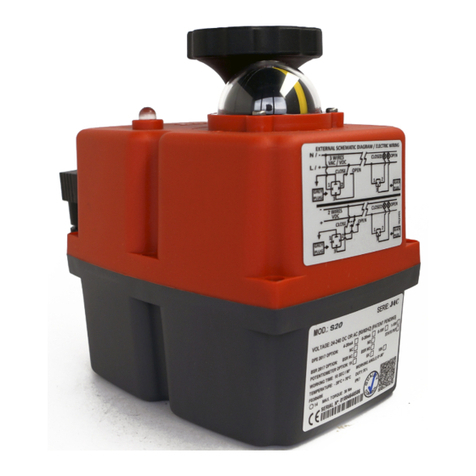
J4C 20 User manual

Installaon instrucons 2402 V3
(EN) J4C 20 TO 300 INSTALLATION INSTRUCTIONS
(ES) INSTUCCIONES PUESTA EN MARCHA J4C 20 A 300
(FR) INTRUCTIONS D’INSTALLATION J4C 20 A 300
(IT) ISTRUZIONI DI INSTALLAZIONE J4C DA 20 A 300
(DE) KURZANLEITUNG J4C S20-S300
www.jjbcn.com

J4C 20 TO 300 INSTALLATION INSTRUCTIONS (ENGLISH)
VOLTAGE ...................................................................................................................................................................... 03
ELECTRICAL CONNECTORS ........................................................................................................................................... 03
LOCAL VISUAL POSITION INDICATOR............................................................................................................................ 04
EMERGENCY MANUAL OVERRIDE FACILITY .................................................................................................................. 05
EXTERNAL LED LIGHT STATUS....................................................................................................................................... 05
BSR-NC/NO SET-UP ...................................................................................................................................................... 07
DPS .............................................................................................................................................................................. 07
KITS BSR/KIT DPS ......................................................................................................................................................... 08
HEATER ........................................................................................................................................................................ 08
MOUNTING TO COMPONENT BEING ACTUATED.......................................................................................................... 08
INSTUCCIONES PUESTA EN MARCHA J4C 20 A 300 (ESPAÑOL)
VOLTAJE ....................................................................................................................................................................... 09
CONECTORES ............................................................................................................................................................... 09
INDICADOR VISUAL ...................................................................................................................................................... 10
MANDO MANUAL DE EMERGENCIA............................................................................................................................. 11
INDICADOR LUMINOSO................................................................................................................................................ 11
BSR-CONFIGURACIÓN BSR NC - BSR NO....................................................................................................................... 13
DPS .............................................................................................................................................................................. 13
KITS BSR/KIT DPS ......................................................................................................................................................... 14
CALEFACTOR ................................................................................................................................................................ 14
MONTAJE DE LOS COMPONENTES AL ACTUADOR........................................................................................................ 14
INTRUCTIONS D’INSTALLATION J4C 20 A 300 (FRANÇAIS)
TENSION ...................................................................................................................................................................... 15
CONNECTEURS............................................................................................................................................................. 15
INDICATEUR VISUEL ..................................................................................................................................................... 16
COMMANDE MANUALLE D’URGENCE.......................................................................................................................... 17
INDICATEUR LUMINEUX ............................................................................................................................................... 17
BSR-CONFIGURATION BSR NC - BSR NO ....................................................................................................................... 19
DPS .............................................................................................................................................................................. 19
KITS BSR/KIT DPS ......................................................................................................................................................... 20
HEATER ........................................................................................................................................................................ 20
MONTAGE DES COMPOSANTS DE L’ACTIONNEUR ........................................................................................................ 20
ISTRUZIONI DI INSTALLAZIONE J4C DA 20 A 300 (ITALIANO)
TENSIONE..................................................................................................................................................................... 21
CONNETTORI................................................................................................................................................................ 21
INDICATORE ................................................................................................................................................................ 22
COMANDO MANUALE D’EMERGENZA.......................................................................................................................... 23
SPIA LUMINOSA ........................................................................................................................................................... 23
BSR-CONFIGURAZIONE BSR NC - BSR NO ..................................................................................................................... 25
DPS .............................................................................................................................................................................. 25
KITS BSR/KIT DPS ......................................................................................................................................................... 26
HEATER ........................................................................................................................................................................ 26
MONTAGGIO DEI COMPONENTI ALL’ATTUATORE ......................................................................................................... 26
KURZANLEITUNG J4C S20-S300 (DEUTSCH)................................................................................................ 27
INDEX

(ENGLISH)J4C 20 TO 300 INSTALLATION INSTRUCTIONS_3
INDEX
Read these instructions before connecting the actuator. Damage caused by non compliance
of these instructions is not covered by our warranty.
J4C Electric actuators operate with the use of live electricity. It is recommended that only qualified electrical
engineers be allowed to connect or adjust these actuators.
VOLTAGE
• All our actuators model S20 to S300 are ready to work from 24-240 VDC/VAC.
• All our actuators model B20 to B300 are ready to work at 12 VDC/VAC.
ELECTRICAL CONNECTORS
Warning: Before connecting ensure that the voltage to be applied to the actuator is within the range shown on the
water tightness.
Connector Small Black Big Grey or Black
EN175301-803 Form CI EN175301-803 Form A
Model min. Ø max. Ø min. Ø max. Ø
J4C 20 to 300 5 mm 6 mm 8 mm
Warning:
the cable be sure that sealing 5 and 9 are well installed. Failure to do so could allow water ingress and damage
123
4
5
6
7
8910
11
1. Gasket
2. Terminal strip
4. Housing
5. Washer
6. Grommet
7. Gland - nut
8. Gasket
9. Washer
11. ESD cap
ELECTROSTATIC DISCHARGE IMMUNITY (ESD): The added ESD cap
(11) serves as component aimed at preventing any adverse effects
of electrostatic discharges. Its primary function is to ensure optimal
performance and extended durability for the actuator. Acting as a
safeguard, this additional component strengthens the actuator’s
immunity to ESD, signicantly enhancing its overall lifespan.

(ENGLISH)J4C 20 TO 300 INSTALLATION INSTRUCTIONS_4
INDEX
LOCAL VISUAL POSITION INDICATOR
All J4C actuators are supplied with a local visual position indicator comprises a black base with a yellow
Opening = Closing =
A
A
B
B
ON - OFF VDC
A= Power supply plug (Grey plug)
B= Volt free contact plug (Black plug)
A B
ON - OFF VAC
A= Power supply plug (Grey plug)
B= Volt free contact plug (Black plug)
A
A
C
C
B
B
POSITIONER VAC VDC
A= Power supply plug (Grey plug)
B= Volt free contact plug (Black plug)
C
Important!
(risk of self adjustment)
MAX 10V

(ENGLISH)J4C 20 TO 300 INSTALLATION INSTRUCTIONS_5
INDEX
EMERGENCY MANUAL OVERRIDE FACILITY
J4C
half of the actuator housing (Fig 7).
•
•
EXTERNAL LED LIGHT STATUS
LED status light provides visual communication between the actuator and the user.
LED light:
Warning:mecha
nism to become loose and will cause irreparable damage to the actuator’s gearbox.Removing
this screw will invalidate the warranty.
When “AUTO” position is selected:
actuator could suffer unrepairable damages.
Fig. 7 J4C 20 TO 85 Fig. 7 J4C 140 TO 300
1.
3.
4.
•
automatically again.
•
actuator and it could operate automatically again.

(ENGLISH)J4C 20 TO 300 INSTALLATION INSTRUCTIONS_6
INDEX
ACTUATOR ON-OFF OPERATIONAL STATUS
Actuator without power being supplied
Open Actuator
Close Actuator
connection (Standard mode only)
Actuator opening
Actuator closing
Actuator in middle position. For a 3 position actuator only
Actuator without power and working with the
LED STATUS
ACTUATOR WITH POSITIONER OPERATIONAL STATUS
Actuator without power supply
Actuator in the correct position
Actuator opening
Actuator closing
For 3 min Max.
For 3 min Max.
LED STATUS

(ENGLISH)J4C 20 TO 300 INSTALLATION INSTRUCTIONS_7
INDEX
BSR plug-in failsafe system,
NO (Normally Open) or NC (Normally Close).
Set up by using the SELDIR Jumper (Fig.9): NC: jumper on / NO: jumper off.
B
(Fig. 11).
A. plug - Connect voltage to the actuator in the following way:
VAC: PIN1 (neutral) and PIN2 (phase).
Fig.10
Place the DIPS (Fig. 10) according to the signal you need to work with.
J4C 20 to 85 J4C 140 to 300
Jumper SELDIR
Jumper SELDIR
Fig. 9 Fig. 9
BSR -NC/NO SET-UP
DPS
External adjustment
BSR - NC/NO SET-UP
BSR
NO (Normally Open) or NC (Normally Close).
Set up by using the SELDIRNC: jumper on / NO: jumper off.
DPS
Place the DIPS (Fig. 10) according to the signal you need to work with.
C.
A.
4/20 mA
NC 0/10 V
NC
1/10 V
NC
4/20 mA
NO
0/10 V
NO
1/10 V
NO
BSR plug-in failsafe system,
NO (Normally Open) or NC (Normally Close).
Set up by using the SELDIR Jumper (Fig.9): NC: jumper on / NO: jumper off.
B
(Fig. 11).
A. plug - Connect voltage to the actuator in the following way:
VAC: PIN1 (neutral) and PIN2 (phase).
Fig.10
Place the DIPS (Fig. 10) according to the signal you need to work with.
J4C 20 to 85 J4C 140 to 300
Jumper SELDIR
Jumper SELDIR
Fig. 9 Fig. 9
BSR -NC/NO SET-UP
DPS
External adjustment

(ENGLISH)J4C 20 TO 300 INSTALLATION INSTRUCTIONS_8
INDEX
*
Cplug
C.
Fig. 11
J4C 20 to 85 COVER J4C 140 to 300 COVER
A C B A C B
KITS BSR / KIT DPS
HEATER
MOUNTING TO COMPONENT BEING ACTUATED (Ex:1/4 turn valve)
wherever possible as it greatly assists in ensuring the concentricity of mounting the actuator to the valve.
drive when the assembly is bolted together.
Failure to comply with these instructions will cause uneven wear and dramatically reduce the working life of the valve and actuator.
.
diagram on the label of the actuator. We recommend that
could protect the actuator against other electrical devices.
separately for proper management before being deposited
at the collection facilities. Batteries may contain hazardous
substances that can harm the environment and human
are selective collection programs for used batteries in
Num: RII-AEE: 8760

(ESPAÑOL) INSTUCCIONES PUESTA EN MARCHA J4C 20 A 300 _9
ÍNDICE
Lea atentamente estas instrucciones antes de la conexión del actuador. el incumplimiento de
estas instrucciones deja sin efecto todo tipo de garantía.
solo personal especializado efectúe las conexiones o ajustes del actuador.
A continuación explicaremos la función de cada uno y como manipularlos.
VOLTAGE
• 24-240 VDC/VAC.
• 12 VDC/VAC.
CONECTORES
Atención:
Conector Pequeño negro Grande gris o negro
EN175301-803 Form CI EN175301-803 Form A
Modelo min. Ø max. Ø min. Ø max. Ø
J4C 20 a 300 5 mm 6 mm 8 mm
Es muy importante
tengan las respectivas juntas bien montadas.
123
4
5
6
7
8910
11
1 Junta
2 Base conector
4 Conector
5 Junta cable
6 Grapa sujeción
7 Tuerca
8. Junta tornillo
9. Arandela
11. tapón ESD
INMUNIDAD A DESCARGAS ELECTROSTÁTICAS (ESD): La tapa ESD
agregada (11) sirve como componente destinado a prevenir cualquier
efecto adverso de las descargas electrostáticas. Su función principal es
garantizar un rendimiento óptimo y una mayor durabilidad del actuador. Al
actuar como protección, este componente adicional fortalece la inmunidad
del actuador a ESD, mejorando signicativamente su vida útil general.

(ESPAÑOL) INSTUCCIONES PUESTA EN MARCHA J4C 20 A 300 _10
ÍNDICE
ON - OFF VAC
A
B= Contactos auxiliares (conector negro)
INDICADOR VISUAL
La barra amarilla nos indica la posición del actuador y el sentido de rotación (Fig. 6 ). Cuando la barra
se encuentra en posición de cerrado.
A
A
B
B
ON - OFF VDC
A
B= Contactos auxiliares (conector negro)
A B
A
A
C
C
B
B
POSICIONADOR VAC VDC
A
B= Contactos auxiliares (conector negro)
C
Importante!
(riesgo de autoajuste)
MÁX 10V

(ESPAÑOL) INSTUCCIONES PUESTA EN MARCHA J4C 20 A 300 _11
ÍNDICE
MANDO MANUAL DE EMERGENCIA
•
•
INDICADOR LUMINOSO
ATENCIÓN
Cuando el actuador se encuentra en posición “AUTO
mente y nunca debe ser obstruido o detenido este movimiento.
Fig. 7 J4C 20 A 85 Fig. 7 J4C 140 A 300
Tornillo
seguridad
1.
3.
4. Si la palanca selectora se encuentra en “MAN
• a) Con el actuador en posición “MAN
AUTO
• b) Posicionar la palanca selectora de “MANAUTO

(ESPAÑOL) INSTUCCIONES PUESTA EN MARCHA J4C 20 A 300
ÍNDICE
ESTATUS OPERACIONAL DEL ACTUADOR ON-OFF
Actuador sin alimentación
Actuador abierto
Actuador cerrado
Desconexión de motor por tiempo
Actuador en posición intermedia.
Solo para actuadores de 3 posiciones
Actuador sin alimentación.
Max. 3 min.
LUMÍNICA
ESTATUSOPERACIONALDELACTUADORCONPOSICIONADOR
Actuador sin alimentación
Actuador en la posición correcta
Desconexión de motor por tiempo
Actuador
Max. 3 min.
LUMÍNICA

(ESPAÑOL) INSTUCCIONES PUESTA EN MARCHA J4C 20 A 300 _13
ÍNDICE
BSR plug-in failsafe system,
NO (Normally Open) or NC (Normally Close).
Set up by using the SELDIR Jumper (Fig.9): NC: jumper on / NO: jumper off.
B
(Fig. 11).
A. plug - Connect voltage to the actuator in the following way:
VAC: PIN1 (neutral) and PIN2 (phase).
Fig.10
Place the DIPS (Fig. 10) according to the signal you need to work with.
J4C 20 to 85 J4C 140 to 300
Jumper SELDIR
Jumper SELDIR
Fig. 9 Fig. 9
BSR -NC/NO SET-UP
DPS
External adjustment
BSR-Configuración BSR NC - BSR NO
Si la unidad dispone de un sistema BSR
“NONCSELDIR
NCNO
DPS
trabajar.
Autoregulación externa
Conector C - Hacer un cruce entre el PIN1 (PIN derecha) y el PIN TIERRA (PIN inferior). (Fig.11) Conector
A - Conectar voltaje al actuador de la siguiente manera:
VAC: PIN1 (neutro) y PIN2 (fase).
VAC: PIN1 (negativo) y PIN2 (positivo).
4/20 mA
NC 0/10 V
NC
1/10 V
NC
4/20 mA
NO
0/10 V
NO
1/10 V
NO
BSR plug-in failsafe system,
NO (Normally Open) or NC (Normally Close).
Set up by using the SELDIR Jumper (Fig.9): NC: jumper on / NO: jumper off.
B
(Fig. 11).
A. plug - Connect voltage to the actuator in the following way:
VAC: PIN1 (neutral) and PIN2 (phase).
Fig.10
Place the DIPS (Fig. 10) according to the signal you need to work with.
J4C 20 to 85 J4C 140 to 300
Jumper SELDIR
Jumper SELDIR
Fig. 9 Fig. 9
BSR -NC/NO SET-UP
DPS
External adjustment

(ESPAÑOL) INSTUCCIONES PUESTA EN MARCHA J4C 20 A 300 _14
ÍNDICE
*
l actua
Fig. 11
J4C 20 to 85 COVER J4C 140 to 300 COVER
A C B A C B
KITS BSR / KIT DPS
interior de los respectivos kits.
CALEFACTOR
MONTAJE DE LOS COMPONENTES AL ACTUADOR
actuador.
Recomendamos que el actuador tenga un sistema independiente
de fusibles para protegerle de otros aparatos
(p.e. bombas).
importante extraerlas antes de su depósito en las instalaciones
de recogida de estos residuos. Las pilas y baterías pueden
ambiente y la salud humana si se manejan de manera
incorrecta o se eliminan incorrectamente.
tiendas de electrónica u otros establecimientos donde se
pueden depositar las pilas y baterías para su posterior tratamiento
y reciclaje adecuado. Num: RII-AEE: 8760

(ENGLISH)J4C 20 TO 300 INSTALLATION INSTRUCTIONS_15
INDEX
(FRANÇAIS) INTRUCTIONS D’INSTALLATION J4C 20 A 300_15
ces instructions annule tout type de garantie
Les actionneurs J+J Séries J4C 20 à 300 utilisent de l’énergie électrique pour leur fonctionnement. Nus
rappelons que, seul, le personnel spécialisé peut effectuer les branchements ou les réglages de l’actionneur.
VOLTAGE
S20 à S300 sont prêts à fonctionner à partir de 24-240 VDC/VAC.
B20 à B300VDC/VAC.
ELECTRICAL CONNECTORS
Attention :
CONNECTEUR Petit NOIRE Grand GRIS ou NOIRE
EN175301-803 Form CI EN175301-803 Form A
MODÈLE min. Ø max. Ø min. Ø max. Ø
J4C 20 to 300 5 mm 6 mm 8 mm
Il est important
123
4
5
6
7
8910
11
1 Joint connecteur
2 Base connecteur
4 Connecteur
7. Écrou
8. Joint vis
9. Rondelle
11. ESD cap
IMMUNITÉ AUX DÉCHARGES ÉLECTROSTATIQUES (ESD) : Le capuchon
ESD ajouté (11) sert de composant visant à prévenir tout effet néfaste
des décharges électrostatiques. Sa fonction principale est d’assurer
des performances optimales et une durabilité prolongée de l’actionneur.
Agissant comme une protection, ce composant supplémentaire renforce
l’immunité de l’actionneur contre les décharges électrostatiques,
augmentant ainsi considérablement sa durée de vie globale.
Register.

(ENGLISH)J4C 20 TO 300 INSTALLATION INSTRUCTIONS_16
INDEX
(FRANÇAIS) INTRUCTIONS D’INSTALLATION J4C 20 A 300_16
Raccorder l’alimentation au connecteur gris “A
Raccorder le retour de position au connecteur noir “B
A
A
B
B
A B
A
A
C
C
B
B
INDICATEUR VISUEL
Fig. 6 90 = ouvert
Raccorder l’alimentation au connecteur gris “A
Raccorder le retour de position au connecteur noir “B
Raccorder l’alimentation au connecteur gris “A
B
connecteur central “C
Important !
MAX 10V

(ENGLISH)J4C 20 TO 300 INSTALLATION INSTRUCTIONS_17
INDEX
(FRANÇAIS) INTRUCTIONS D’INSTALLATION J4C 20 A 300_17
COMMANDE MANUALLE D’URGENCE
•
•
ATC
INDICATEUR LUMINEUX
ATTENTION :
Fig. 7 J4C 20 A 85 Fig. 7 J4C 140 A 300
Vis de
sécurite
1.
2.
3.
4. Si le levier se trouve sur “MAN
a) Avec l’actionneur sur “MAN
b) Positionner le levier de “MANAUTO

(ENGLISH)J4C 20 TO 300 INSTALLATION INSTRUCTIONS_18
INDEX
(FRANÇAIS) INTRUCTIONS D’INSTALLATION J4C 20 A 300_18
ÉTAT DE LA LED
Déconnexion programmée du moteur
RESET est nécessaire.
STATUT OPERATIONNEL DE L’ACTIONNEUR AVEC POSITIONNEUR
STATUT OPERATIONNEL DE L’ACTIONNEUR ÉTAT DE LA LED
(-) + PIN2+3 (F) o (+) (Modus Standard)
Déconnexion programmée du moteur
- INTRUCTIONS D’INSTALLATION J4C 20 A300
06
INDEX
FRANÇAIS

(ENGLISH)J4C 20 TO 300 INSTALLATION INSTRUCTIONS_19
INDEX
(FRANÇAIS) INTRUCTIONS D’INSTALLATION J4C 20 A 300_19
BSR plug-in failsafe system,
NO (Normally Open) or NC (Normally Close).
Set up by using the SELDIR Jumper (Fig.9): NC: jumper on / NO: jumper off.
B
(Fig. 11).
A. plug - Connect voltage to the actuator in the following way:
VAC: PIN1 (neutral) and PIN2 (phase).
Fig.10
Place the DIPS (Fig. 10) according to the signal you need to work with.
J4C 20 to 85 J4C 140 to 300
Jumper SELDIR
Jumper SELDIR
Fig. 9 Fig. 9
BSR -NC/NO SET-UP
DPS
External adjustment
BSR: configuration BSR NC - BSR NO
· NC: jumper monté
· NO: jumper non monté.
DPS
signal à utiliser
VAC :
VDC :
4/20 mA
NC 0/10 V
NC
1/10 V
NC
4/20 mA
NO
0/10 V
NO
1/10 V
NO
BSR plug-in failsafe system,
NO (Normally Open) or NC (Normally Close).
Set up by using the SELDIR Jumper (Fig.9): NC: jumper on / NO: jumper off.
B
(Fig. 11).
A. plug - Connect voltage to the actuator in the following way:
VAC: PIN1 (neutral) and PIN2 (phase).
Fig.10
Place the DIPS (Fig. 10) according to the signal you need to work with.
J4C 20 to 85 J4C 140 to 300
Jumper SELDIR
Jumper SELDIR
Fig. 9 Fig. 9
BSR -NC/NO SET-UP
DPS
External adjustment

(ENGLISH)J4C 20 TO 300 INSTALLATION INSTRUCTIONS_
INDEX
(FRANÇAIS) INTRUCTIONS D’INSTALLATION J4C 20 A 300
* IMPORTANT :
central de l’actionneur « C »
Fig. 11
J4C 20 to 85 COVER J4C 140 to 300 COVER
A C B A C B
KITS BSR / KIT DPS
respectifs.
HEATER
MONTAGE DES COMPOSANTS DE L’ACTIONNEUR
substances dangereuses qui peuvent nuire à l’environnement
Num: RII-AEE: 8760
This manual suits for next models
5
Table of contents
Languages:
Other J4C Controllers manuals
Popular Controllers manuals by other brands

Monoprice
Monoprice RVC25-70 Quick install guide

All Motion
All Motion EZ Stepper Ez4Axis quick guide

Syntec
Syntec S08-SMD-33B Series installation instructions

Mitsubishi Electric
Mitsubishi Electric MELSEC Q Series user manual

Agilent Technologies
Agilent Technologies TwisTorr 74 FS user manual

Superwinch
Superwinch 06702 owner's manual

MKS
MKS 250E instruction manual

Hydrofarm
Hydrofarm autopilot APC8400 user manual

National Instruments
National Instruments myRIO-1950 instructions

Quantum
Quantum NE PLUS Basic operation instructions

BADU
BADU BNR 300 Installation & operating instructions

Emerson
Emerson Asco 642 Series Installation and maintenance instructions