manuals.online logo
Brands
  1. Home
  2. •
  3. Brands
  4. •
  5. jablotron
  6. •
  7. Controllers
  8. •
  9. jablotron GD-06 ALLEGRO User manual

jablotron GD-06 ALLEGRO User manual

GD-06 ALLEGRO GSM dealer 1/2 MHG51302
GD-06 ALLEGRO GSM Dialer
The GD-06 ALLEGRO is a universal GSM dialer and
controller. It can be used for both home and industrial
automation purposes, for security applications or any remote
data transfer project. Triggering of any of the inputs will
cause the sending of a reporting SMS message to
preprogrammed phone numbers or a direct call to a
telephone number. By using specific text messages, you can
switch on or off the remote controlled outputs. In the basic
setting, the GD-06 provides 4 inputs and 3 outputs.
The device can be programmed using programming SMS
messages or via the Internet using Jablotron’s GSMLink web
page.
The Expert mode enables full programming of all inputs and
outputs, trigeering a listening-in mode, GPRS data
communication and analogue data transmission.
1. Specification
Power supply voltage 8 - 15 V DC
Current consumption 20 mA (stand-by), 500 mA
(maximum)
GSM band E-GSM/GPRS 900/1800MHz
(2 W @ GSM900, 1 W @
GSM1800)
Terminals (P1 - P6): Input mode - triggered when
connected to GND (200 ms
filter is used)
Output mode - transistor output (max. 100 mA), switches to
GND
Relay output over-switching contact (NC-C-
NO), max. 2A / 24V
Dimensions 76 x 110 x 33 mm (antenna -
125 mm)
Complies with EN 60950, EN 301489-7, ETSI
EN 301489-7, EN55022, EN
50130-4, EN 301511
Hereby, Jablotron Ltd., declares that this GD-06 complies with the
essential requirements and other relevant provisions of Directive
1999/5/EC. Original conformity assessment can be found at the web
page www.jablotron.cz, section Technical support.
2. Installation
The GD-06 ALLEGRO is designed for indoor use only.
Check the GSM signal strength before installing the product
(e.g. with a GSM phone using a SIM card for the same
operator).
1) Insert a SIM card into a GSM phone and disable its PIN.
If you cannot disable it, set it to 1234.
2) Insert the SIM card into the GD-06.
3) Connect the power supply.
4) The LED will start flashing until the SIM card registers
into the GSM operator’s network (max. 1 minute).
5) Standby mode is then indicated by short flashes of the
LED (apr. once every 2 sec). If the LED is lit
permanently, GSM communication is in progress.
Terminals’ description:
Wire outputs of your triggering devices (e.g. sensors, alarm
systems…) to corresponding input terminals of GD-06. Wire
the appliances which you want to control remotely to the
output terminals of the GD-06.
Note: After the installation, all telephone numbers are erased
from the memory and access codes are set to MASTER and
USER.
3. Basic setting
3.1. Reset
Reset the GD-06 communicator to the factory default
settings with English communication by sending the
instruction
“MASTER RESET EN” to the dialer.
3.2. Telephone numbers setting
Store the telephone numbers TEL1 to TEL8 using the
programming SMS instruction sent from a GSM phone:
MASTER TELXYYY ZZZZZZZZZZZ
Parameter Value Description
X 1,2,3,4,5,6,7,8 Memory position for TEL1
to TEL8
SMS Instruction to send SMS to
this number
YYY SMS+ Instruction to send SMS to
this number first and then
to call this number
ZZZZZZZZZ
Telephone number (max
20 digits) , “+” prefix can
be used for international
calls
Example: “MASTER TEL1 SMS 00420483559911”
You will then receive a confirmation message from the GD-
06 to your mobile phone.
Notes:
• There must be spaces between the parameters. The SMS
instruction is case insensitive.
• For telephone numbers TEL7 and TEL8, which are used
for remote control only, you can use any YYY parameter.
• To delete the telephone number, send the SMS instruction
“MASTER TELX DEL”, for example “MASTER TEL3
DEL”.
• If the confirmation message is not in English, reset the GD-
06 as described in the paragraph 3.3.
Terminal Mode Telephone
numbers
Power
supply +U
GND
Terminals for connecting
8-15 V DC power supply
voltage -
Inputs
P1
P2
P3
P4
Connecting or disconnecting
to GDN will trigger sending
SMS
information to all telephone
numbers TEL1 – TEL6.
Example: "P1 On" or “P2 Off"
TEL1, TEL2,
TEL3, TEL4,
TEL5, TEL6
P5
P6
SMS instruction sent from
TEL1-TEL8 telephones
controls
the outputs.
Example: "ON P5" or “OFF
P6"
TEL1, TEL2,
TEL3, TEL4,
TEL5, TEL6,
TEL7, TEL8
Outputs
NC
C
NO
Relay switches over
(on/off/on…)
whenever a phone call from
TEL1 or TEL2 is detected.
TEL1, TEL2
GD-06 ALLEGRO GSM dealer 2/2 MHG51302
3.3. Customization of SMS texts and access
codes
The default texts of reporting SMS and incoming SMS
instruction can be modified using the following programming
SMS: MASTER TXT index, text
index index number according to the following
table text new text, which will be used in SMS
messages
Basic SMS reports’ texts
Index Default Description
10 P1 Description of P1 input terminal
11 On P1 input terminal is triggered
20 P2 Description of P2 input terminal
21 On P2 input terminal is triggered
30 P3 Description of P3 input terminal
31 On P3 input terminal is triggered
40 P4 Description of P4 input terminal
41 On P4 input terminal is triggered
Basic SMS instructions’ texts
Index Default Description
50 P5 Description of P5 output terminal
60 P6 Description of P6 output terminal
70 RELAY Description of the relay output
100 ON Instruction to switch on an output
101 OFF Instruction to switch off an output
109 USER User access code
110 MASTER Master access code
You can send multiple texts separated by commas and blank
spaces in one programming SMS.
Examples:
a) “MASTER TXT 10, Security system, 11, armed” will
customize the input P1 setting to indicate a security
system’s status. If a corresponding alarm system
output triggers the P1 when arming, then SMS
report “Security system armed” is sent.
b) “MASTER TXT 71, Heating” will modify the remote
SMS instruction to switch on a heating system
connected with the relay output to “Heating on”.
c) “MASTER TXT 110, Big elephant” will change the
master access code to “Big elephant”
4. Operation
After installation of the GD-06 ALLEGRO and programming
of the telephone numbers, the GD-06 is ready for operation.
• Triggering of any input P1 to P4 will cause the sending
of a SMS report to the telephones registered in the
positions TEL1 to TEL6.
• From a GSM phone, you can send an SMS instruction
to switch on or off the P5 and P6 outputs.
• You can also switch the relay on or off by making a
phone call to the GD-06 from a phone registered to
TEL1 or TEL2 memory positions. The GD-06 ALLEGRO
doesn’t answer this call, so you don’t pay any
telecommunication fee for this remote control.
Notes:
1. You can remotely control the GD-06 from any phone:
not only from the ones stored in the memory TEL1-
TEL6. You just have to add the master (default
MASTER) or user (default USER) access code in front
of the instruction.
Example: “MASTER ON P5”
2. The SMS instructions texts are case insensitive. It
means that instruction “ON P5” is equal to “on p5”.
5. Advanced programming
More detailed programming can be accomplished from
Internet using the web page www.gsmlink.cz. Follow the
product registration instructions to get access to a secure
web page. Use the registration code printed on the warranty
certificate (the code has a form xxxx-xxxxx-xxxx and it is
unique for each system). From the GSMLink, you can
program your GD-06 ALLEGRO easily regardless of where
in the world you are located. The best performance will be
obtained if your SIM card enables GPRS data transmission.
Form the GSMLink server you can:
• Check the current status of all inputs and outputs
• Control the outputs
• Program the GD-06
• Change the SMS tetxts (only when GPRS data
connection is enabled)
If you don’t have Internet access, you can also use SMS for
the advanced programming. You can find all details in the
Expert programming manual.

Other jablotron Controllers manuals

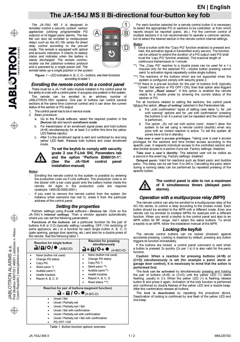
jablotron JA-154J MS II User manual

jablotron

jablotron JA-154J MS II User manual

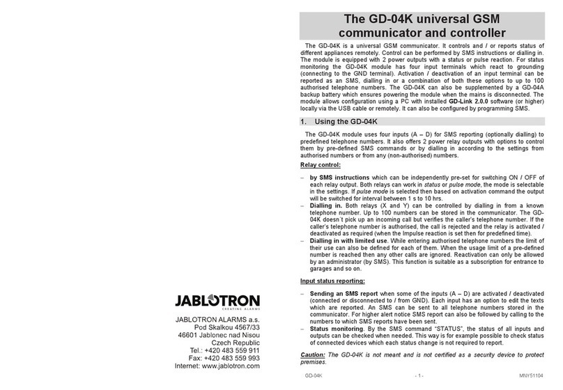
jablotron GD-04K User manual

jablotron

jablotron GD-04K User manual

Popular Controllers manuals by other brands

Zamel RZB-05 quick guide

Zamel

Zamel RZB-05 quick guide

YOKOGAWA UT32A-D Operation guide

YOKOGAWA

YOKOGAWA UT32A-D Operation guide

DINUY KNX RE KNT DA1 Installation

DINUY

DINUY KNX RE KNT DA1 Installation

Munters TRIO user manual

Munters

Munters TRIO user manual

Inovance Easy320 user guide

Inovance

Inovance Easy320 user guide

Troy-Bilt 49M2027P966 Operator's manual

Troy-Bilt

Troy-Bilt 49M2027P966 Operator's manual

Omron E5ED-8 Series instruction manual

Omron

Omron E5ED-8 Series instruction manual

dixell CX620 Installing and operating instructions

dixell

dixell CX620 Installing and operating instructions

PI M-228 Series user manual

PI

PI M-228 Series user manual

Itowa LS2 user manual

Itowa

Itowa LS2 user manual

ACME LED MOOD Series user manual

ACME

ACME LED MOOD Series user manual

wtw OxiTop C operating manual

wtw

wtw OxiTop C operating manual

GF Signet 9900-1BC product manual

GF

GF Signet 9900-1BC product manual

P&B MPC2000D manual

P&B

P&B MPC2000D manual

Desa JourneyMan HD-9260 user manual

Desa

Desa JourneyMan HD-9260 user manual

Mastervolt MASTERLINK MICC user manual

Mastervolt

Mastervolt MASTERLINK MICC user manual

HS-Technik NetBee operating instructions

HS-Technik

HS-Technik NetBee operating instructions

Chauvet Obey 40 user manual

Chauvet

Chauvet Obey 40 user manual

manuals.online logo
manuals.online logoBrands
  • About & Mission
  • Contact us
  • Privacy Policy
  • Terms and Conditions

Copyright 2025 Manuals.Online. All Rights Reserved.