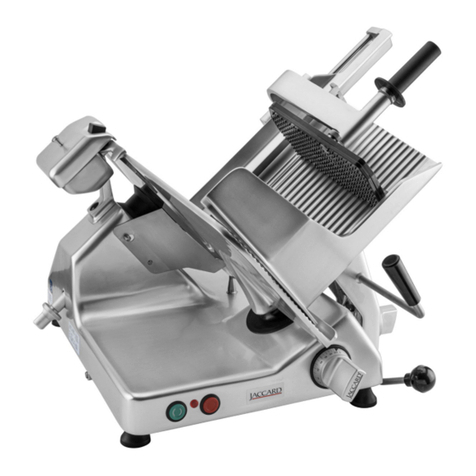
Jaccard VA 4000 AT Operating instructions

technical alterations and alterations
regarding accessories reserved
Operating Instructions for Conveyor Belt
Model
VA 4000 AT
Jaccard Corporation
70 Commerce Drive
Rochester, NY 14623
Telephone 1-716-825-3814
ACCARD
LEGENDARYQUALITYSINCE1962

Page 2
Contents
1. INSTALLATION AND INITIAL OPERATION 3
1.1. INSTALLATION 3
1.2. ELECTRICAL INSTALLATION 3
2. OPERATION 3
3. CLEANING 4

Page 3
1.
Installation and initial operation
Read these operating instructions as well as the operating instructions for the VA 4000 completely. These
additional instructions are only a supplement.
Only operate the machine according to the instructions.
Always work with care to avoid damage or injury. The installation, introduction and initial operation must
be done by an authorized supplier or service technician.
1.1.
Installation
Install the food slicer model VA 4000 on the supplied stand. Make
sure that the feet of the machine are placed into the cups fixed on the
stand.
Place the front end of the conveyor belt up on the base of the machine and slide it
securely over the mounting bolt. Make sure that the power plug is located on the left
side of the conveyor. Then lower the conveyor into the mounting brackets of the
support arm.
Make sure that both sides of the conveyor are supported and that it is securely in
place.
1.2.
Electrical installation
The conveyor belt is powered by the VA4000. Plug the conveyor belt power cord into the corresponding socket,
located at the front of the machine. Make sure to secure the plug into position by
tightening the outer safety locking ring.
2.
Operation
The operating instructions of the VA4000 are described in the “Operating instructions
for Food Slicer VA4000”. The only variation during programming will be the need for
the input of the desired distance between sliced portions. This input of disctance will
be necessary for all slicing programs for the conveyor belt to move forward and to separate the sliced portions.
Once the machine has been started, it will run continuously. There are three instances where the slicing
procedure will be stopped
1. The food product has run out. The machine stops and the end piece holder moves
back to the beginning of the carriage
2. The portions are reaching the end of the conveyor belt, are activating the end
switch, which will cause the slicer to stop slicing.
3. The slicing prodedure is interrupted by pushing the "start/stop" button or the
emergeny stop button.
Once the slicer stopped production, a previously placed stack of product will remain near the stacking arm. If the
machine resumes the slicing, the new portion would be positioned on top of the previously sliced one.
To avoid this, push the “B” button first. The conveyor belt will move forward the same distance which is used in
the current slicing program. However, this only applies if the conveyor belts’ end switch was not activated..

Page 4
3. Cleaning
The machine must be cleaned prior to initial operation and after a longer period of standstill.
In accordance with FDA regulations, the slicer must be cleaned at least once every 4 hours if kept at room
temperature. Cleaning may be necessary more frequently at higher temperatures or when slicing products that
may harden on the blade like cheeses, soft meats, etc.
It is recommended to disconnect the conveyor belt from the machine for better cleaning.
After unplugging it from the VA4000, make sure that both parts of the power conectors have their protective caps
securely in place so that no moisture can enter the electrical system. Clean the belts and the metal base with
soapy water and cleaning cloths, using anti-bacterial detergent as described in the “Cleaning and Sanitizing
procedure VA4000 Slicers”.
For a quick cleaning between slicing sessions, the conveyor belt can be cleaned while it is connected to the
machine base.
Press and hold the "cleaning" button. Release the button after 5 seconds and the conveyor belts will start moving.
Pushing the "cleaning" button again quickly will stop the conveyor belt.
Be careful when cleaning the machine, especially in the area of the blade.
To carry out the cleaning process, refer to the work instruction WI-Maintenance-001; Cleaning and Sanitizing
Procedure provided by Jaccard in the manual kit with this machine.

Illustrated Parts Manual for Food Slicer
Model
VA 2000
VA 4000
Jaccard Corporation
70 Commerce Drive
Rochester, NY 14623
Telephone 1-716-825-3814
ACCARD
LEGENDARYQUALITYSINCE1962

page 2
Contents
1. EXPLODED DRAWINGS AND PART LISTINGS 3
1.1. DRAWING 1: MACHINE BODY –BASE 3
1.2. DRAWING 2: MACHINE BODY –COMPLETE 5
1.3. DRAWING 3: DISPLAY SUPPORT TUBE 6
1.4. DRAWING 4: STACKING DEVICE BASE PLATE 7
1.5. DRAWING 5: MAGNETIC SOLENOID ASSEMBLY 8
1.6. DRAWING 6: LIGHT BARRIER FOR STACKING DEVICE 9
1.7. DRAWING 7: STOP PIN FOR CHAIN ASSEMBLY 10
1.8. DRAWING 8: BUFFER 1 10
1.9. DRAWING 9: BUFFER 2 11
1.10. DRAWING 10: PIN FOR PIVOT BEARINGS 11
1.11. DRAWING 11: METAL PLATE FOR MICRO SWITCH ASSEMBLY 12
1.12. DRAWING 12: DEFLECTION ROLLER (2 PER MACHINE) 12
1.13. DRAWING 13: STEP MOTOR FOR RECEIVING PLATE 13
1.14. DRAWING 14: GUIDED MECHANISM FOR RECEIVING PLATE 14
1.15. DRAWING 15: STACKING DEVICE ASSEMBLY 15
1.16. DRAWING 16: CARRIAGE SLIDING SUPPORT ASSEMBLY 16
1.17. DRAWING 17: CARRIER FOR CARRIAGE DRIVE 18
1.18. DRAWING 18: CHAIN FRAME DRIVE 19
1.19. DRAWING 19: SYNCHRONIZING PLATE ASSEMBLY (TOP) 20
1.20. DRAWING 20: SYNCHRONIZING PLATE ASSEMBLY (BOTTOM) 21
1.21. DRAWING 21: COVER FOR CHAIN DRIVE BEARING 21
1.22. DRAWING 22: STEP MOTOR FOR CHAIN DRIVE 22
1.23. DRAWING 23: CHAIN DRIVE ASSEMBLY 23
1.24. DRAWING 25: PRESS ROLLER ASSEMBLY 24
1.25. DRAWING 26: DEFLECTING COMB BRACKET 25
1.26. DRAWING 27: INDEX MECHANISM ASSEMBLY 26
1.27. DRAWING 28: ADJUSTING BLOCK ASSEMBLY 28
1.28. DRAWING 29: INDEX GUIDE STRAP ASSEMBLY 29
1.29. DRAWING 30: THICKNESS PLATE SUPPORT ASSEMBLY 30
1.30. DRAWING 31: POTENTIOMETER ASSEMBLY 30
1.31. DRAWING 32: CARRIAGE CHAIN TENSIONER ASSEMBLY 31
1.32. DRAWING 33: CHAIN WHEEL CARRIER ASSEMBLY 32
1.33. DRAWING 34: CHAIN DRIVE COVER PLATE 33
1.34. DRAWING 38: TENSIONER ASSEMBLY 34
1.35. DRAWING 39: DEFLECTION ROLLER FOR BASE PLATE 35
1.36. DRAWING 40: CARRIAGE ASSEMBLY (MEDIUM) 36
1.37. DRAWING 43: PRODUCT SUPPORT ARM (MEDIUM) 37
1.38. DRAWING 45: DRIVING UNIT FOR END PIECE HOLDER (MEDIUM) 38
1.39. DRAWING 46: LOWER FOOD PLATE 40
1.40. DRAWING 47: END PIECE HOLDER ASSEMBLY 41
1.41. DRAWING 50: CARRIAGE SUPPORT ARM ASSEMBLY 42
1.42. DRAWING 51: BLADE GUARD ASSEMBLY 43
1.43. DRAWING 52: DEFLECTOR ASSEMBLY 44
1.44. DRAWING 53: MOTOR ASSEMBLY 45
1.45. DRAWING 54: BLADE HUB ASSEMBLY 46
1.46 DRAWING 55: FOOT ASSEMBLY 47

page 3
1.
Exploded Drawings and Part Listings
1.1.
Drawing 1: Machine Body –Base
REF. #
DESCRIPTION
PART#
1
Base plate
20.000.00
2
Machine body complete (Drawing 2)
20K001.00
3
Holding tube assembly (Drawing 3 –VA4000 only)
20K009.00
4
Stacking device base assembly (Drawing 4)
20K050.00
5
Carriage sliding support assembly (Drawing 16)
20K100.00
6
Chain drive unit for chain assembly (Drawing 18)
20K230.00
7
Support assembly (Drawing 27)
20K370.00
8
Chain tensioner assembly (Drawing 32)
20K400.00
9
Chain wheel carrier assembly (Drawing 33)
20K430.00
10
Cover plate assembly (Drawing 34)
20K450.00
11
Foot assembly (Drawing 35)
20Z007J00
14
Adjuster assembly (Drawing 38)
20K011.00
15
Deflection roller for base plate assembly (Drawing 39)
20K017.00
16
Cable cover
20.008.00
17
Cover plate –rear
20.015.00
3
2
23
•

page 4
18
Spacer for carriage guide bar
20.018.00
19
Carriage guide bar –short
27.001.40
20
Support for guide bar
06.338.01
21
Conical pressure spring
52.001.00
22
Carriage guide bar
13.001.40
23
Bottom plate
20.016.00
24
Washer
590125044
25
Toothed washer
556797043
26
Lens head screw
607985408
27
Washer
599021085
28
Toothed washer
556797084
29
Socket screw
609120825
30
Washer
590125065
31
Spring washer
590127006
32
Socket screw
609120620
33
Countersunk screw
609630411
34
Threaded pin
545510620
35
Hex nut
606923006
36
Spring washer
590137008
37
Spring washer
590127008
38
Socket screw
609120865
39
Socket screw
609120840
40
Socket screw
607984820

page 5
1.2.
Drawing 2: Machine Body –Complete
REF. #
DESCRIPTION
PART#
2.1
Machine body assembly
20Z001.00
2.2
Cover plate for side plate (front)
20.001.40
2.3
Cover plate for stacking device
20.001.50
2.4
Countersunk screw
609630306
2.5
Countersunk screw
609630310
I I D --
$ I
'
24: : t: ~~
2.4 _J,_..______ :[__ 2.4
=- 24
~
$
-2.1
2.5 ---~--,-,.. $ I
.-- 2.5
2.5
2.3
2.5 ~-- - - ~ 2.5

page 6
1.3.
Drawing 3: Display Support Tube (VA4000 only)
REF. #
DESCRIPTION
PART#
2
Holding tube body assembly (Drawing 2)
20K001.00
3.1
Holding tube assembly
20Z009.00
3.2
Holding tube mount assembly
15Z800.00
3.3
Cylinder screw
600840406
3.4
Wing screw
57.002.10
3.5
Welded threaded bolt
544000616
3.6
Washer
599021065
3.7
Hex nut
609850006
34 tF . ~ 33
I I .:---2
35 ---rn r 35
3.2
3.6 ----+ +- 36
37 ~ ,.j_- 37

page 7
1.4.
Drawing 4: Stacking Device Base Plate
REF. #
DESCRIPTION
PART#
4.1
Stacking device base plate
20.050.00
4.2
Magnetic solenoid assembly (Drawing 5)
20K807.00
4.3
Chain lock
75.008.10
4.4
Toothed washer
556797055
4.5
Hex screw
609330520
4.6
Light barrier for stacking device assembly (Drawing 6)
20K806.00
4.7
Chain frame mount assembly (Drawing 7)
20K061.00
4.8
Buffer 1 assembly (Drawing 8)
20K058.00
4.9
Buffer 2 assembly (Drawing 9)
20K059.00
4.10
Holder for buffer
20.054.00
4.11
Washer
590125051
4.12
Cylinder screw
609120540
4.13
Countersunk screw
609630515
4.14
Pin bearing assembly (Drawing 10)
20K051.00
4.15
Retaining ring
590472019
4.16
Deep groove ball bearing
50.618002
4.17
Pivot bearings assembly
20K052.00
4.18
Washer
599021053
4.19
Hex nut
609850005
4.40 --i..tea:=-
.9
Wf
t.- 4.3
4.7
4.2
4.35 4.22
I
I
! 4.23
-
.
.

page 8
4.20
Shaft seal
56.223278
4.21
Threaded rod for transformer
20.057.00
4.22
Transformer for VA2000
Transformer for VA4000
13.155.62
13.155.90
4.23
Hex nut
609340008
4.24
Metal plate for micro switch assembly (Drawing 11)
15Z810.00
4.25
Hex screw
609330510
4.26
Cylinder screw
609120520
4.27
Bearing for step motor
15.051.00
4.28
Deflection roller for stacking device assembly(Drawing 12)
20K056.00
4.29
Washer
599021e43
4.30
Toothed washer
556797043
4.31
Hex nut
609340004
4.32
Step motor for receiving plate assembly (Drawing 13)
15K002.75
+15.011635
4.33
Cylinder screw
600840420
4.34
Dry plain bearing
61.001612
4.35
Guiding mechanism for receiving tray assembly (Drawing 14)
20K151.00
4.36
Grooved taper pin
541471516
4.37
Washer
599021065
4.38
Toothed washer
556797065
4.39
Hex screw
609330625
4.40
Stacking arm assembly (Drawing 15)
20K080.00
4.41
Receiving tray assembly
15K500.03
1.5.
Drawing 5: Magnetic Solenoid Assembly
REF. #
DESCRIPTION
PART#
4.2.1
Magnetic solenoid
51.071.00
4.2.2
Adaptor for magnetic solenoid
15.059.00
4.2.3
Hex nut
609340006
4.2.4
Hex nut
604390006
4.2.4
13:E:::342~ 23,, 2/ 5

page 9
4.2.5
Roll for chain
75.008.00
1.6.
Drawing 6: Light Barrier for Stacking Device
REF. #
DESCRIPTION
PART#
4.6.1
Plate for light barrier –stacking device
20.806.00
4.6.2
Distance bushing
01.215.01
4.6.3
Light barrier
51.202.00
4.6.4
Cylinder screw
600840310
4.6.5
Hex nut
609340003
4.6.6
Cylinder screw
609120530
4.6.7
Toothed washer
556797055
4.6.8
Washer
599021053
4.6.7
4.6.8
4.6.2
4.6.6
4.6.1
t- ~--- 4.6.3
w.~--- 4.6.4
=j=~===::~;w.- 4.6.5
~-

page 10
1.7.
Drawing 7: Stop Pin for Chain Assembly
REF. #
DESCRIPTION
PART#
4.7.1
Washer
20.061.00
4.7.2
Adjusting ring
59070508A
4.7.3
Threaded pin
549160403
4.7.4
Hex nut
609340008
4.7.5
Washer
590125085
1.8.
Drawing 8: Buffer 1
REF. #
DESCRIPTION
PART#
4.8.1
Buffer 1
20.058.00
4.8.2
Buffer plate assembly
20K060.00
4.8.3
Hex nut
609340008
4J5
4B3

page 11
1.9.
Drawing 9: Buffer 2
REF. #
DESCRIPTION
PART#
4.9.1
Buffer 2
20.059.00
4.8.2
Buffer plate assembly
20K060.00
4.9.2
Hex nut
609340008
1.10.
Drawing 10: Pin for Pivot Bearings
REF. #
DESCRIPTION
PART#
4.14.1
Bolt for pivot bearing
20.051.00
4.14.2
Flange for pivot bearing
20.051.10
4.14.3
Hex nut for pivot bearing
20.051.20
4.14.4
Washer for pivot bearing
20.051.30
4.9.2 4.9.1
4.8.2
J
4.14.2
4.14.1

page 12
1.11.
Drawing 11: Metal Plate for Micro Switch Assembly
REF. #
DESCRIPTION
PART#
4.24.1
Metal plate for micro switch
15.810.00
4.24.2
Quick break switch
51.000.10
4.24.3
Cylinder head screw
600840310
4.24.4
Toothed washer
556797033
4.24.5
Hex nut
609340003
1.12.
Drawing 12: Deflection Roller (2 per machine)
REF. #
DESCRIPTION
PART#
4.28.1
Hex screw
609330630
4.24.4 ----------
4.24.3
~
7--
4.24.1
------- 4.24.4
-r ----e::===S--
~ 4.28.5
4.28.4

page 13
4.28.2
Spring washer
590127006
4.28.3
Washer
590125065
4.28.4
Washer
599021065
4.28.5
Spring washer
590988061
4.28.6
Needle bearing
50.NKI616
1.13.
Drawing 13: Step Motor for Receiving Plate
REF. #
DESCRIPTION
PART#
4.32.1
Step motor
15.002.72
4.32.2
Synchronizing disc
15.011635
4.32.3
Threaded pin
549160304
4.32.1
blue ~ 4.32.3
~ '"'
2.9

page 14
1.14.
Drawing 14: Guided Mechanism for Receiving Plate
REF. #
DESCRIPTION
PART#
4.35.1
Guiding mechanism for receiving tray
20Z151.00
4.35.2
Guiding bracket
20.153.00
4.35.3
Locking mechanism 1 for receiving tray
15.506.00
4.35.4
Locking mechanism 2 for receiving tray
15.507.00
4.35.5
Switch plate for micro switch
15.809.00
4.35.6
Synthetic guide for tray
15.811.00
4.35.7
Rubber ring
17.050.00
4.35.8
Brecoflex Toothed belt
53.003.05
4.35.9
Countersunk screw
609630411
4.35.10
Threaded pin
545510516
4.35.11
Hex nut
609340005
4.35.12
Washer
599021053
4.35.13
Toothed washer
556797055
4.35.14
Hex screw
609330510
Q--- 4.35.4 ~ 4.35.3 ~ 4.35.6
4.35.2 ~ 4.35.12
_j x-- 4.35.13
Ji!i- 4.35.14
4.35.9 4 35 5
4.35.~ 4.35.7 / . 4.35.10 4.35.11
1r,-----_j
□
-ct
...-ct~~'
tb-
4.35.1

page 15
1.15.
Drawing 15: Stacking Device Assembly
REF. #
DESCRIPTION
PART#
4.40.1
Stacking device assembly
20K081.00
4.40.2
Tilting joint assembly
20K084.00
4.40.3
Nylon plug for stacking device
15.605.00
4.40.4
Hex nut
15.602.00
4403 ~
4.40.1
4.40.4
4.40.2·------,r-==o
w

page 16
1.16.
Drawing 16: Carriage Sliding Support Assembly
REF. #
DESCRIPTION
PART#
5.1
Sliding support
20.100.00
5.2
Carriage locking pin
20Z101.00
5.3
Knob
06.131.00
5.4
Grip for engaging pin
06.132.00
5.5
Contact sheet for light barrier
20.807.00
5.6
Tensioning strap
15.002.65
5.7
Carrier for Carriage drive assembly (Drawing 17)
20K110.00
5.8
Spring holder
20.105.00
5.9
Torsion spring
20.106.00
5.10
Connecting bolt
20.104.00
5.11
Strap
20.107.00
5.12
Short tube
20.112.00
5.13
Long tube
20.113.00
5.14
Curved tube
20.114.00
5.15
Bolt for carriage drive
20.103.00
5.16
Retaining ring
590471012
5.17
Deep groove ball bearing
50.6001ZZ
5.18
Threaded pin
549160612
5.19
Cam for carriage guide rod
20.115.00
5.14
Table of contents
Other Jaccard Kitchen Appliance manuals